In agriculture there has always been a high demand for the use of high-power wheeled tractors. One of the most productive in its class at the moment is KhTZ-17221. With the help of this technology it is possible to implement a large number of different tasks during agricultural work and not only.
The prototype of HTZ-17221 is a tractor labeled T-150K. Compared to its earlier analogue, HTZ-17221 has not only greater comfort, a changed appearance, but also high performance. It increased by more than 20%. This allows you to complete transportation and other tasks much faster.
Over time, HTZ-17221 was modernized. First of all, attention was paid to the comfort of the driver. There is a vibration isolation system, as well as thermal and sound insulation. Which also has a positive effect on labor productivity.
HTZ-17221: history of creation
The place of development of HTZ-17221 is the Kharkov Tractor Plant. More than one hundred thousand tractors for various purposes rolled off the assembly line of this production. The plant was developing not only tractors, but also all kinds of attachments. In fact, KhTZ was focused specifically on agriculture. In addition to wheeled tractors, all kinds of tracked vehicles were produced.
In 2006, the Kharkov Tractor Plant, in addition to the HTZ-17221 model under consideration, also produced modernized versions of the T-150, as well as the tracked HTZ-181. Machines for farming work – KhTZ-3510 – were in great demand. Since 2007, the plant's losses began to increase more and more with each reporting period. At the end of 2015, the liquidation of the Kharkov Tractor Plant began. For this reason, KhTZ-17221 was no longer produced at KhTZ.
However, the Russian and Ukrainian markets are filled with a large number of spare parts. Moreover, both new and already used. It is not difficult to purchase a used HTZ-17221, both in working condition and for disassembly.
Reviews about the tractor HTZ 17221
antonpedan HTZ-17221-19 - 212 hp. the farm was purchased through Tekhnotorg in the fall of 2010. During operation, the engine oil was replaced twice and once in all other components, while the tractor plowed 135 hectares of corn and disced 200 hectares of sunflower with DMT 4A twice (I think you can plow 400 hectares). Liked; quite powerful, Czech fuel and turbine (when the turbine turns on you feel in your body that the car is a beast) the seats will be appreciated by everyone without exception, 10 hours behind the wheel pass unnoticed. Did not like; At the end of the season, oil started leaking from under the main one. In reality, in order to make a tractor out of HTZ, you need to cut the hell out of this cabin and put a Djonovskaya or a Keisovskaya one there. Just everything. And there will be an inexpensive tractor for people.
RULY1 HTZ 17221 is a lottery. Either you will have no grief with him, or you will experience grief. 70% for what you eat. The fuel pump doesn’t run more than 5000, the turbines fly, the blocks burst, the pump goes dead. Very sensitive to diesel fuel. The regulators have a problem, which can really be solved with a rusty nail from the fence. Horror….
Specifications
Before purchasing the tractor model in question, you must carefully familiarize yourself with its performance characteristics.
Dimensional and mass indicators
At the moment, both the weight and overall dimensions of the HTZ-17221 depend on the specific modification. They look like this:
| Modification | HTZ-17221 | HTZ-17221-21 | HTZ-17221-19 |
| Parameter | |||
| Base, mm | 2 860 | 3 360 | 2 860 |
| Track, mm | 1 860 | 1 860 | 1 860 |
| Length, mm | 6 000 | 6 000 | 6 500 |
| Width, mm | 2 460 | 2 460 | 2 460 |
| Height, mm | 3 360 | 3 330 | 3 360 |
| Ground clearance, mm | 450 | 450 | 450 |
| Operating weight, kg | 8 980 | 8 870 | 8 480 |
Overall dimensions differ significantly due to the use of engines of various modifications, as well as differences in the basic configuration. The design differs depending on the purpose of the specific type of tractor.
Engine
Today, depending on the modification, the HTZ-17221 can use different engines. At the moment, the following units can be installed:
- YaMZ-236D-3;
- YaMZ-238KM2-3;
- D-260.
The main parameters of these units are as follows:
| Parameter | YaMZ-236D-3 | YaMZ-238KM2-3 | D-260 |
| Rated power, hp | 180 | 240 | 210 |
| Crankshaft rotation speed, rpm | 2 100 | 2 100 | 2 100 |
| Number of cylinders, pcs. | 6 | 8 | 6 |
| engine's type | V-shaped | V-shaped | Row |
| Bore/Stroke | 130/140 | 130/140 | 110/125 |
| Engine displacement, l. | 11.5 | 14.86 | 7.14 |
| Launch | electric starter | ||
| Fuel consumption, g/kW/h | 224 | 251 | 240 |
Transmission
In HTZ-17221 only a manual gearbox is installed. There is a special hydraulic drive that reduces the required force to a minimum.
The checkpoint has the following parameters:
- a hydromechanical drive is used;
- There are 12 speeds to select the optimal driving mode;
- switching on the go is possible - no interruption of movement is required;
- total number of forward speed ranges/speeds – 3/12;
- total number of reverse ranges/speeds – 0.25;
- the main gear is conical, it includes a spiral tooth and a cross-axle differential;
- The crank gear is in the form of a single-stage planetary gearbox.
There are also some features depending on the type of motor used:
| Unit type | YaMZ-236D-3 | YaMZ-238KM2-3 | D-260 |
| Travel speed, km/h, forward | 3.7-5.8 7.81-12.2 17-29 | 3.7-5.8 7.81-12.29 17.96-29.60 | |
| Travel speed, km/h, reverse | 5.6-8.8 | 5.10-9.14 | 5.1-9.1 |
Chassis (transmission)
On the KhTZ-17221 used today, the transmission consists of:
- dry, single-plate clutch;
- hydromechanical gearbox.
Also an integral part of the transmission is the power take-off shaft. It is located at the rear and has as many as 2 speeds. The speed range of some modifications of the HTZ-17221 is quite large even compared to foreign analogues:
- 8 speeds for reverse movement;
- 16 forward speeds.
Cabin HTZ-17223. Tractor control
One of the main advantages of this tractor is the cabin. It is equipped with the following:
- double-glazed windows - it is possible to operate the equipment even at low negative temperatures;
- air conditioning and heating systems - which increases labor productivity, since driver fatigue is reduced during work.
All controls are located within reach of the driver. The KhTZ-17223 cabins of the last years of production before the liquidation of the plant have some shortcomings:
- poor sound insulation - immediately after purchase it is worth laying another layer of special material;
- there are holes in the cabin connecting the engine compartment to the cabin - they need to be sealed;
- The windows should be redesigned so that they open in the other direction, in the direction of movement of the tractor (otherwise all the dust will end up inside the cab during operation).
Device
Among other things, unlike the basic version, the machine from the Kharkov Tractor Plant has a number of design features. In particular we are talking about the frame.
Photo of tractor HTZ-17221
Frame, power plant
In essence, KhTZ-17221 is a heavily modernized T-150K. A special feature of this tractor was its breakable frame, consisting of two half-frames connected by hinges. These hinges allow you to change the angle of position between the half-frames in the vertical and horizontal planes.
The power unit is installed on the front half-frame. For this modification it is YaMZ-236M2. The power plant is covered on all sides by the hood; there are two removable side panels for access to the engine.
The clutch housing is attached to the engine. The clutch itself in HTZ-17221 is frictional, using one driven disk. The clutch control mechanism is additionally equipped with a pneumatic booster.
Transmission
The clutch casing is connected to the gearbox, which in this tractor is mechanical, equipped with friction hydraulic clutches, which allows it to change gears without interrupting the power flow. But this switching ability is only possible within the range. Having 4 gear ranges for forward movement and 2 ranges for reverse, a significant number of gearbox gears is provided, since each range has 4 gears.
Ranges and gears are controlled by two different levers. This number of gears allows you to optimally select the traction force for a certain type of work, which affects fuel consumption.
The gearbox housing also houses a transfer case, from which there is a permanent drive to the rear axle. The front axle of the tractor can be disabled. These parts of the transmission are also located on the front frame.
The rear semi-frame is allocated for the rear drive axle, hydraulic separate-unit system, power take-off shaft, and trailer-mounted equipment.
Hydraulic system
The hydraulic system provides the tractor with the ability to interact with various equipment. To work with hydraulically controlled mechanisms, a connection block with couplings is installed near the rear wings, through which the hydraulic equipment of the mechanism is connected. The mechanism equipment is controlled from the cabin. This system is also equipped with automatic adjustment of the position of attachments, which allows, albeit to a small extent, to save fuel.
To connect the tractor with mounted mechanisms, a hitch is used, which includes two hydraulic cylinders in its design. The hitch also allows the tractor to be connected to semi-mounted and trailed mechanisms and trailers, since it includes a towing device, a tow bar and a tie bar.
Chassis
The tractor is controlled by a hydraulic steering mechanism, and it is combined with a separate hydraulic system. The tractor turns by changing the angle between the semi-frames - the frame “breaks”. This is achieved through the use of two hydraulic cylinders installed between the semi-frames.
The two drive axles installed on the tractor are identical in design, differing only in the position of the main gear housing and the long axle shafts, respectively.
The main gears themselves are identical and interchangeable. Both axles also include an automatic differential lock.
The front axle is connected to the front semi-frame by means of two semi-elliptic springs, additionally equipped with shock absorbers. The rear axle is rigidly attached to its half-frame. The dimensions of all 4 wheels installed on the tractor are the same. The tires on the tractor are pneumatic, low pressure.
The cabin is closed, frame type, installed behind the hood. Designed for two people. The cab is attached to the tractor using 4 rubber shock absorbers. The fuel tank is located behind the cabin.
Tractor modifications
At the moment, there are only three different modifications of this type of equipment:
- HTZ-17221;
- HTZ-17221-21;
- HTZ-17221-19.
All the models indicated above have a general purpose and differ only in the engines installed in them. As a result, the volume of filling tanks, as well as the location of the units. The regular HTZ-17221 model today is equipped with a YaMZ-236D-3 engine. It has the following distinctive features from the others:
- minimum turning radius, m – 6.6;
- oil quantity: in the gearbox, l – 18;
- in both bridges, l – 50;
- in a hydraulic mounted system, l – 46;
- in the power steering system, l – 35.
The traction force of this model is 3,000-6,000 kgf. Water and antifreeze are used as a cooling fluid. Depending on the time of year. Cooling system volume – 45 l.
Basic modification HTZ-17221
HTZ-17221-21 is a more advanced version of this tractor. It has slightly larger overall dimensions and the most powerful engine among other modifications. The main differences between the parameters of this model include the following:
- minimum turning radius, m – 6.7;
- amount of oil in the engine, l – 31.3;
- filling capacities, l: in the gearbox – 18;
- in drive axles – 54;
- in the hydraulic system - 46;
- in the steering system - 35;
- in PTO – 6.8.
Despite the lack of a special purpose for the modification of the HTZ-17221-21 tractor, it is used not only in agriculture, but also in construction and felling. Since it has a relatively small size and excellent cross-country ability.
Modification of tractor HTZ-17221-21
KhTZ-17221-19 is also equipped with a domestically produced motor. Its power is 210 hp.
Modification of tractor HTZ-17221-19
The distinctive features of this technology include the following:
- minimum turning radius, m – 6.7;
- amount of oil in the engine, l – 21;
- other filling capacities: in the gearbox, l – 18;
- in drive axles, l – 54;
- in the hydraulic system, l – 46.
Model range of tractor HTZ 17221
The expanded capabilities of technology and its economic efficiency gave impetus to its further development. After some modifications, the HTZ-17221-09 model appeared. It has a modified shape, in particular, due to the use of a single-seat cabin in the design. Models KhTZ-17221-19 and KhTZ-17221-21 have more serious changes related to the power of the device. The first copy is equipped with a 6-cylinder D-260 diesel engine, but the second one has an almost twice as powerful 8-cylinder YaMZ-238.
Tractor HTZ 17221 in the field
Operating experience. Advantages and disadvantages
The model of wheeled tractor for agriculture under consideration has both its advantages and disadvantages. If possible, before purchasing, you should familiarize yourself with the complete list of all the weak points of this equipment.
During the first 12 years of operation, the following components and parts fail :
- water pump - circulating through the cooling system;
- cuff of the pump that pumps fuel (2 times in a row);
- bearing seal (rear main).
Users have the following main comments regarding the tractor itself:
- after 3 years of operation, the input shaft of the gearbox was replaced;
- after 4 years, the hydraulic clutch for engaging the third gear was replaced;
- The steering metering pump was replaced;
- The feredo, one of the clutch discs, has been replaced.
Attention should be paid to the main disadvantages of the type of tractor under consideration:
- poor ventilation, noise;
- it is possible to open only the side windows;
- when driving, dirt flies off the front wheels and enters the cabin;
- After 2 years of operation, the rear fenders will need to be replaced.
The cable control of the units does not show itself well. If possible, it is worth converting it into a lever one.
The issue with ventilation and heating is solvable.
The main positive aspects of the HTZ-17221 tractor include the following:
- unpretentiousness to fuel quality;
- endurance and engine power - even a 180-horsepower tractor is superior in performance to its analogues;
- ease of repair - almost all breakdowns can be eliminated on your own with minimal knowledge and skills in repairing such equipment;
- All design and assembly shortcomings can be eliminated with your own hands - while spending a minimum amount of time.
HTZ-17221
The T-150K tractor served as the basis for the creation of the 170 series of wheeled tractors, but with the designation KhTZ. One of the models in this series is the HTZ-17221 tractor, the production of which began in 1997.
KhTZ-17221 is a general purpose equipment and is designed to perform heavy agricultural work - plowing, disking, cultivation, fertilizing, etc.
.
HTZ-17221 earned mostly positive reviews from agricultural workers. The equipment turned out to be reliable; malfunctions that arose during operation were usually minor. In terms of performance, the tractor also turned out to be up to par.
The disadvantages of this tractor most often include an ill-conceived cabin, the disadvantage of which is poor sound insulation and tightness. Many owners of these tractors are already eliminating these shortcomings themselves.
Prices for used tractor HTZ 17221
The cost of the type of tractor in question on the secondary market depends on two different parameters: year of manufacture and operating hours.
| Year of issue | Number of engine hours worked | Cost, rub. |
| 2006 | 2 000 | 1 400 000 |
| 2008 | 2 300 | 1 690 000 |
| 2004 | 4 300 | 300 000 |
Before purchasing a used tractor of this model, you should familiarize yourself with all possible breakdowns in advance and pay attention to weak points. In the future, this will avoid unnecessary investments in tractor repairs. Low cost may be the reason for the high cost of repairing equipment.
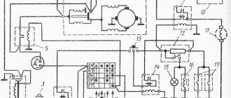
Tractors HTZ-181 and T-150-05-09-25. Electrical equipment
content .. 5 6 7 8 ..List of elements of the electrical connection diagram for electrical equipment of tractors T-150-05-09-25 and HTZ-181
(Figure 43, inset) Table 6
Position,
designation
| Name | Col. | Note | |
| A | Switch panel | 1 | |
| KV1* | Rear work light relay | 1 | ** |
| SA4 | Switch for operating modes of electric motors of fans of a heating and ventilation unit (air conditioner) | 1 | ** |
| SA6 | Air conditioning compressor drive electric coupling switch | 1 | ** |
| SA7 | Rear window wiper mode switch | 1 | ** |
| SA10 | Rear work light switch | 1 | ** |
| SA11 | Front work light switch | 1 | ** |
| SA12 | Rear window wiper mode switch | 1 | ** |
| SA14 | Front window wiper operating mode switch | 1 | ** |
| IN | Fuel gauge sensor | 1 | |
| VR1 | Water temperature indicator sensor in the engine cooling system | 1 | |
| VR2 | Sensor for alarm temperature of coolant in engine cooling system | 1 | |
| VK1 | Oil pressure indicator sensor in the engine lubrication system | 1 | |
| VK2 | Engine oil filter clogging sensor | 1 | Set engine |
| VK3 VK4 | Emergency oil pressure indicator sensor in the engine lubrication system Oil pressure indicator sensor in the gearbox hydraulic system | 1 | |
| VK7 | Engine air cleaner filter warning sensor | 1 | |
| VK10 | Oil pressure indicator sensor in the PTO hydraulic system | 1 | |
| VK11 | Air conditioner thermostat sensor | 1 | |
| VK12 | Air conditioner emergency pressure sensor | 1 | |
| E EL1, EL2 EL5, EL9 | Radio Transport headlight with lamp A12-45+40 Front working headlight with lamp AKG 12-55-1 | 1 | |
| EL10 EL11, EL12, EL13, EL14 | Cabin light with lamp A12-21-3 Rear working headlight with lamp AKG 12-55-1 | 1 | |
| EL15 | License plate light with lamp A12-5 | 1 | |
| F1 | Fuse block 11.3722.000 with two fuse links 60A | 1 |
**Items included in switch panel A.
| Position, designation | Name | Col. |
| F2, F3 | Fuse block PR-120-01 with fuse links | 2 |
| GB1 | Generator | 1 |
| GB2, GB3 | Rechargeable battery 6 ST-140A3 | 2 |
| GB4 | Voltage transformer | 1 |
| H.A. | Sound signal | 1 |
| HL2, HL4, HL5, HL6, HL11 | Warning lamp | 5 |
| M1 | Starter | 1 |
| M2 M3, M6 | Windshield washer motor Front windshield wiper motor | 1 |
| M4 | Heater motor | 1 |
| M5 | Fan motor | 1 |
| KV1 | Starter activation relay | 1 |
| KV2 | Starter blocking relay when the engine is running | 1 |
| KV4 | Horn relay | 1 |
| SA1 | Ground switch | 1 |
| SA2 | Starter switch | 1 |
| SA5 | Switch for low and high beam headlights | 1 |
| SA13 | Backlight switch | 1 |
| SB1 | Reversing light switch (blocking engine starting with starter) | 1 |
| SB2 | Ground switch (remote) | 1 |
| SB3 | Hazard warning lamp control switch | 1 |
| SB4 | Horn switch | 1 |
| SB4A | Windshield washer motor switch | 1 |
| XT1 | Cigarette lighter | 1 |
| XT2 | Plug socket PS 300A3-100 for connecting trailer electrical equipment | 1 |
| P1 P2 | Oil pressure indicator in the engine lubrication system Oil pressure indicator in the gearbox hydraulic system | 1 |
| P3 | Oil pressure indicator in the hydraulic system of the PTO gearbox | 1 |
| PV | Voltage indicator | 1 |
| PS1 | Coolant temperature gauge in the engine cooling system | 1 |
| PS2 | Fuel level indicator | 1 |
| PS3 | Tachometer with hour meter | 1 |
| ME | Electric coupling for air conditioning compressor drive | 1 |
The electrical circuits of electricity consumers on tractors are protected from short circuits by fuse blocks 12 and 19 (Figure 7). On the inside of the unit cover there are fuse location plates shown in Figure 43.
To maintain electrical equipment in good condition, clean devices and wires from dust and dirt, monitor the cleanliness of electrical equipment assembly units and the condition of wire insulation: remove damaged areas by wrapping them with PVC insulating tape. Check the reliability of fastening of electrical equipment and instrumentation, ensure that headlights are installed and adjusted correctly, and carefully protect switching equipment and devices from moisture.
ATTENTION! To avoid failure of the generator, tachometer, and voltage converter, operating the tractor without batteries is not allowed.
Before repairing electrical equipment, remove the terminals from the batteries.
ATTENTION! All repair work related to the use of electric welding directly on the tractor or machine (implement) connected to the tractor should be carried out with the ground switch turned off and the power battery cables removed. Use electric welding only with direct current. AC welding is not permitted. The parts to be welded must be grounded at the place where the welding work is carried out.
It is recommended to repair electric motors, generators and starters in repair shops.
When replacing lamps and headlights, make sure that dust and dirt do not get inside the optical elements. Replace damaged lenses with new ones. If the headlight reflector mirror becomes dirty, wash it with cotton wool in clean warm water and dry it with the mirror facing down. It is not recommended to remove stains that appear on the surface of the reflector after drying.
To avoid overheating, subsequent warping, damage to lighting and light signaling devices, it is not allowed to install lamps in them that are more powerful than those installed at the manufacturer.
It is not allowed to use metal objects not intended for this purpose as fusible links.
It is not allowed to check the serviceability of electrical circuits “for a spark”.
ATTENTION! Protect electrical equipment and devices from contact with water, fuel and oil. It is not allowed to wash the inside of the cabin with a jet of water.
Depending on the climatic region in which the batteries operate, fill them with electrolyte, the density of which must correspond to that indicated in Table 7.
Proper operation of batteries and careful care ensure reliable and quick starting of the tractor and increase the service life of electrical equipment. When servicing batteries, read their instruction manual.
Table 7
| Climatic region | Time | Electrolyte density, normalized to 15°C, g/cm3 | |
| of the year | poured | at the end of the first charge | |
| Areas with sharply continental climate | Winter | 1,290 | 1,310 |
| volume with winter temperatures below minus 40°C | Summer | 1,250 | 1,270 |
| Northern regions with winter temperatures down to minus 40°C | All year round | 1,270 | 1,290 |
| Central regions with winter temperatures down to minus 30°C | Same | 1,250 | 1,270 |
| Southern regions | Same | 1,230 | 1,250 |
Perform preventive measures at least once every two weeks:
— clean the batteries from dust and dirt, wipe the electrolyte on the surface of the batteries with a clean rag soaked in a 10% solution of ammonia or soda ash. Clean oxidized battery terminals and wire tips and, after installing them, lubricate the battery terminals with a thin layer of technical petroleum jelly;
— check the fastening of the batteries in the socket, the reliability of the electrical contact between the wire tips and the battery terminals. Do not allow tension on the wires to avoid damage to the output terminals and the formation of cracks in the mastic;
— clean the ventilation holes in the battery plugs;
— check the electrolyte level with a glass tube with a diameter of 3-5 mm in each battery and, if necessary, add distilled water. The electrolyte level should be 10-15 mm above the safety shield or separator.
During seasonal maintenance, as well as in case of unreliable engine starting, check the state of charge of the batteries by measuring the density of the electrolyte (table with an acid meter (hydrometer) and charge it to 100% with direct current.
Table 8
| Electrolyte density, normalized to 15 °C, g/cm3 | ||
| Battery fully charged | Battery is low | |
| by 25% | by 50% | |
| 1,310 | 1,270 | 1,230 |
| 1,290 | 1,250 | 1,210 |
| 1,270 | 1,230 | 1,190 |
| 1,250 | 1,210 | 1,170 |
| 1,230 | 1,190 | 1,150 |
At the same time, measure the electrolyte temperature to take into account the temperature correction (Table 9).
Table 9
| Electrolyte temperature, °C | Correction to hydrometer reading |
| + 45 | + 0,02 |
| + 30 | + 0,01 |
| + 15 | 0,00 |
| 0 | — 0,01 |
| — 15 | — 0,02 |
| — 30 | — 0,03 |
Table 10
| Electrolyte density, g/cm3 | Freezing temperature, °C |
| 1,100 | -7 |
| 1,150 | -14 |
| 1,200 | -25 |
| 1,250 | -50 |
| 1,275 | -59 |
| 1,300 | -63 |
| 1,310 | -66 |
If the battery is discharged by more than 25%, remove it from the tractor and charge it to 100% capacity in DC mode. Operating batteries with a capacity of less than 75% is not recommended.
To ensure long-term battery life, factories
— Battery manufacturers recommend charging batteries in DC mode to 100% battery capacity during seasonal maintenance.
Remember that at sub-zero temperatures the electrolyte may freeze, causing the battery to fail. The freezing temperature of the electrolyte depending on its density is given in Table 10.
If the batteries are systematically undercharged or the electrolyte boils, check the value of the regulated voltage at terminal “B” of the generator.
ATTENTION! Incorrect connection of batteries to the tractor's electrical network will damage the generator!
It is not allowed to check the serviceability of the battery by the strength of the spark when the battery terminals are shorted together.
To avoid discharging the battery when the engine is stopped, turn it off using the battery disconnect switch.
5.3.9 Caring for seats
The cabin has two seats: a sprung one for the tractor driver and an additional unsprung one. During operation, periodically check the fastening of the seats.
It is recommended to lubricate the moving parts of the seat with grease at least twice a year.
It is not allowed to wash the mechanisms and seat cushions with water.
Wipe the seat upholstery with a weak water solution of detergents that do not contain alkalis, then wipe dry.
The seat provides for quick removal and installation of the cushions when cleaning them by turning special washers on their reverse side.
5.3.10 Use and maintenance of the microclimate system
The tractor is equipped with a microclimate system with air conditioning. By special order, a microclimate system with a heating and ventilation unit can be installed on the tractor.
Figure 44 — Cabin microclimate system with air conditioning
1 - compressor; 2 — air filter; 3 - evaporative heating unit; 4 - deflectors; 5 — refrigeration line “compressor-radiator-condenser”; 6, 8, 17, 22 — sealing rings; 7 — refrigeration pipe “compressor - evaporation-heating unit”; 9 — right engine drainage pipe; 10 — valve for supplying coolant to the evaporation-heating unit; 11 — pipeline for supplying coolant to the evaporation-heating unit; 12 — cold pipe “evaporation-heating receiver unit”; 13 — electrical wiring harness; 14 — pipeline for draining coolant from the evaporation-heating unit; 15 - fitting; 16 — coolant pipe “radiator-condenser-receiver”; 18 — radiator of the gearbox hydraulic system; 19 — radiator-condenser; 20 — radiator of the engine lubrication system; 21 — radiator of the engine cooling system; 23 - receiver
The cabin microclimate system with air conditioning is designed to optimize the microclimate (ventilation, air cooling and heating with heat extraction from the engine cooling system) in the tractor cabin depending on the ambient temperature, as well as creating air pressure in the closed cabin in order to reduce dust in it.
The air conditioner consists of an air filter 2 (Figure 44), an evaporative heating unit 3, a compressor 1, a receiver (filter-drier) 23, a radiator-condenser 19, air ducts, refrigeration pipes 5, 7, 12 and 16, pipelines 11 and 14 supply and discharge of coolant to the evaporative heating unit, tap 10 and deflectors 4. The description, purpose and operation of the system components are given in the operational documentation of the air conditioner.
The electric coupling of the compressor drive is switched on by switch 5 (Figure 9) on the switch panel, the electric motors of the heating and ventilation unit fans are switched on by switch 6 (see subsection 1.4). The compressor drive electric coupling must be turned on after the fan motors are turned on.
The cabin microclimate system with a heating and ventilation unit is designed to supply filtered air into the cabin in the mode of ventilation or heating of the tractor cabin, depending on the ambient temperature, as well as to create air pressure in a closed cabin in order to reduce dust content in it.
The system consists of air filter 2 (Figure 44), a heating and ventilation unit, coolant supply and discharge pipelines, air ducts and deflectors.
The description, purpose and operation of the components of the heating and ventilation unit are given in the operational documentation of the heating and ventilation unit.
Air filter 2 is installed under the cabin roof, the heating and ventilation unit is on the cabin frame, and the deflectors are on the cabin ceiling.
The system can operate in two modes:
— ventilation — the fans of the heating and ventilation unit are turned on and the coolant supply valve to the system installed on the engine drainage pipe is closed (the system is disconnected from the engine cooling system);
— heating the air supplied to the cabin (cabin heating); — the fans of the heating and ventilation unit are turned on, and the coolant supply valve to the system is open (the system is connected to the engine cooling system).
The electric motors of the heating and ventilation unit fans are switched on by switch 6 (Figure 9) on the switch panel.
ATTENTION! Turn on the air conditioner (heating and ventilation unit) only when the engine is running - otherwise the batteries will be discharged.
During the warm season, the coolant supply from the engine cooling system to the cabin air conditioner (heating and ventilation unit) must be turned off. The liquid supply is turned on and off by the coolant supply valve to the system, located on the engine drainage manifold.
Maintenance of the microclimate system is carried out in accordance with this subsection and the operational documentation of the air conditioner (heating and ventilation unit) supplied with the tractor.
To achieve optimal operating conditions and long service life of the microclimate system, it is necessary to regularly carry out preventive inspection and maintenance of the microclimate system.
During repair and maintenance work, it is not allowed to step on the system hoses.
During the summer period of operation (especially during the harvesting period, in conditions of increased dustiness), the following work must be performed:
daily:
- blow radiator-condenser 19 (Figure 44) with compressed air and, if necessary (weakening of the air flow, but at least after 60 operating hours), the air filter;
— check and, if necessary, adjust the tension of the compressor drive belt. The amount of belt deflection with the application of a force of 40 N (4 kgf) to the middle of the belt branch should be 10-15 mm.
weekly:
— check the amount of refrigerant in the microclimate system using the inspection window in receiver 23 (Table 11).
Table 11 - Checking the amount of refrigerant using the sight glass
If there is insufficient refrigerant in the system (excessive gas bubbles are observed through the sight glass), the air conditioner must be turned off to prevent the compressor from overheating;
— blow compressed air through the electromagnetic clutch of compressor 1;
— check the hoses for damage;
— check electrical contacts.
During seasonal maintenance, it is necessary to carry out all the above work and additionally blow out the evaporative heating unit 3 of the air conditioner (heating and ventilation unit) with compressed air.
To clean the filter element 4 (Figure 45) of the air filter, unscrew the handle 5 that secures the frame 8 with the filter element, fold back the frame and remove the filter element. Blow out the filter element with compressed air, first from the clean side, and then from the opposite side and reinstall it in the reverse order.
During seasonal maintenance, rinse the filter element by immersing it in a cleaning solution for 2 hours, rinsing in this solution for 20 minutes and rinsing again in warm (35-40°C) water, dry for 24 hours and reinstall . Prepare a washing solution from paste OP-7 or OP-10 GOST 8433-81 (20 g per 1 liter of water).
It is not recommended to clean filters by striking them against hard objects.
Figure 45 — Installing the air filter
1 - axis; 2 — bracket; 3, 6 — seal; 4 — air filter; 5 — handle; 7 - roof; 8 - frame
The compressor drive belt tension is adjusted using tension bar 3 (Figure 46). The belt deflection should be within 10-15 mm when a force of 4 kgf is applied in the center of the belt.
The belt must be installed on the pulleys manually, without using any tools. It is allowed to use a tool that does not have sharp edges, thereby eliminating damage to the belt and pulley grooves.
If oil, grease or diesel fuel gets on the surfaces of the belt and pulley grooves, immediately remove them with a clean rag, wash the surfaces with soapy water, clean water and wipe dry.
Figure 46 — Adjusting the compressor drive tension
1 — belt 2 cells. 1-11x10-1120; 2 — compressor bracket; 3 — bar; 4, 6, 7, 8 — bolt; 5 - compressor; 9 - engine crankshaft pulley
When dismantling the air conditioner coolant ducts and reinstalling them, O-rings 6, 8, 17 and 22 must be replaced. When connecting refrigeration lines, it is necessary to install O-rings, having previously lubricated them and the threads of the fittings with PAG ZXL 100 PG refrigeration oil.
5.3.11 Care of windshield wipers and washer
The tractor is equipped with two electric windshield wipers for the front and rear windows.
When using windshield wipers, in order to avoid damage to the glass and premature failure of the rubber blades, do not turn them on in the presence of dry dust and dirt without wetting with water. Clean the glass first with a damp cloth.
In winter, when storing the tractor in an open area, remove the windshield wiper blades, as they freeze to the glass, and the rubber quickly breaks down. Before starting the windshield wipers, remove frost or ice from the windows by heating.
In hot weather, when parking the tractor for a long time in an open area, also remove the brushes to avoid cracking of the rubber.
After removing the brushes, put pieces of rubber on the ends of the levers.
or a plastic tube to prevent accidental scratches on the glass. Rinse dirty brushes with water. Do not turn the brush levers by hand, because... in this case, they can be displaced, and the brushes will hit the glass edge.
It is not recommended to raise the levers to the maximum allowable angle to avoid stretching their springs.
When operating the front window wiper, use an electric windshield washer. The windshield washer is activated by push-button switch 18 (Figure 7) in the tractor cabin.
At positive ambient temperatures, fill the windshield washer reservoir with anti-freeze liquid “Obzor-5C”, at negative temperatures - “Obzor-40C”.
It is allowed to use clean fresh water to fill the windshield washer reservoir at positive ambient temperatures, and at temperatures below 0°C any low-freezing liquid.
The presence of mechanical impurities and petroleum products in the liquid filled into the tank is not allowed.
When switching from one fluid to another, it is necessary to remove the old fluid from the pipelines and nozzles by turning on the windshield washer.
Adjust the direction of the jet of washer fluid by turning the ball in the nozzle using a steel wire with a diameter of 0.7 mm.
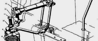
5.3.12 Maintenance of the pneumatic system
The pneumatic system is designed to ensure the operation of the pneumatic booster of the clutch control drive, consisting of a servo mechanism and a brake chamber, and the extraction of compressed air during tractor maintenance.
The diagram of the tractor pneumatic system is shown in Figure 47.
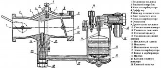
Figure 47 — Diagram of the pneumatic system 1 — compressor; 2 - pressure regulator; 3 — air cylinder; 4 — valve for draining condensate; 5 — brake chamber; 6 — servomechanism; 7 — compressed air tap;
Adjustment of the pressure regulator should be carried out by a qualified mechanic on a special stand.
At the end of each working day, if there is compressed air in the cylinder, open the valve on the air cylinder and drain the condensate. Be especially careful when draining condensate in winter to avoid freezing in the pipes.
When disassembling the tractor, remove the air cylinder and clean the external and internal surfaces with steam and hot water. If corrosion is detected, replace the cylinder. Test the cleaned cylinder hydraulically with a pressure of 1.4 MPa (14 kgf/cm2). Liquid leakage is not allowed. It is not allowed to test the cylinder with compressed air.
Blow out all air ducts and check the tightness of connections and flexible hoses with soap emulsion. Eliminate any leaks found.
Damaged pipelines! and replace flexible hoses. Make sure that the air ducts are secure and not deformed.
During the cold season, check the tightness of the pneumatic system in a warm room so that frozen water in the system thaws. Do not heat the system elements with open fire (blowtorch, torch, etc.).
Perform maintenance and check the operation of the compressor in accordance with the engine operating instructions.
5.3.13 Maintenance of the engine heating system
In order to facilitate engine starting at subzero ambient temperatures, a pre-start heater “Thermo 90ST” (Figure 48) (hereinafter referred to as the heater) can be installed on the tractor upon customer request.
Figure 48 — Heater-heater “Thermo 90ST” 1 — combustion air blower; 2 — connection to the fuel system; 3 - temperature sensor; 4 - heating limiter; 5 - heat exchanger; 6 — coolant inlet; 7 - circulation pump; 8 — coolant outlet; 9 — release of combustion products; 10—combustion air inlet; 11 — control unit (can also be installed separately from the heater)
ATTENTION! Before putting the heater into operation, carefully read the rules of its operation, maintenance, and safety measures set out in the installation instructions for the “Thermo 90ST” heater supplied with the tractor.
REMEMBER! Due to the danger of poisoning and suffocation from exhaust gases, the heater cannot be used indoors (workshops, garages, etc.).
The heater is installed on the front beam of the tractor, operates independently of the engine and is connected to the engine cooling system, fuel and electrical systems of the tractor. Its kit includes: a fuel metering pump installed at the rear of the cab, hoses connecting it to the engine cooling system, a fuel intake pipe, a fuel supply pipe, and a switch.
The connection diagram of the heater to the engine cooling system is shown in Figure 49.
Figure 49 — Connection diagram of the heater to the engine cooling system
Fill the cooling system only with low-freezing liquid.
The heater runs on the same diesel fuel as the engine.
For normal operation of the heater at negative ambient temperatures, in order to avoid thickening of the fuel in the fuel supply pipe to the heater, use only winter grades of diesel fuel.
To heat the coolant in the engine:
— up to a temperature of plus 30°C at an ambient temperature from minus 10°C to minus 20°C;
- up to a temperature of plus 40°C at an ambient temperature below minus 20°C.
Turn the heater on and off using switch 2 (Figure 50), located in the engine compartment, on the left near the radiator guard along the tractor.
Start the heater by turning the switch clockwise, turn it off by turning it counterclockwise to its original position.
The heater turns on automatically within 2-5 minutes. after turning on switch 2. When the temperature of the coolant in the engine cooling system reaches plus 83°C, the heater stops operating, and when the temperature drops, the heater automatically turns on.
After finishing work on the tractor, turn off the heater by turning the switch counterclockwise.
Electrical circuit diagrams and connections of the heater are shown in Figure 50.
Emergency shutdown of the heater is possible in the following cases:
— if a flame does not form, fuel supply continues for no more than 180 s;
— if the flame goes out during operation, the fuel supply continues for no more than 90 s;
— in case of overheating (the heating limiter is activated), there is no fuel supply;
— when turned off due to the activation of undervoltage protection 10.5-0.5 V, which lasts more than 20 s, there is no fuel supply.
After eliminating the cause of the malfunction, remove the emergency lock by turning the heater off and on again. If overheating occurs, return the heat limit switch to its original position.
Diagnostics in case of emergency shutdown of the heater. Check the serviceability of the fuses and plug connectors, the integrity of the electrical wiring, and the absence of a break.
The type of malfunction is determined by the blinking pattern of the light on the switch, which is an indicator of the heater's operation. To do this, you need to count the number of long light bulb pulses that follow after 5 short signals:
1 — no start (after two attempts);
2 — flame breakage (repeated more than five times);
3 - voltage drop below the permissible or voltage increase above the permissible (operating voltage range 10-15V);
4 - premature flame recognition;
5 - open circuit or short circuit of flame sensor 15;
6 - open circuit or short circuit of temperature sensor 14;
7 - open circuit or short circuit of dosing pump 12;
8 - open circuit or short circuit or incorrect speed of the combustion air blower motor 17;
9 - open circuit or short circuit of glow plug 20;
10 - overheating;
11 - open circuit or short circuit of the electric motor of circulation pump 18.
Figure 50 - Electrical diagram of the heater electrical equipment a - basic; b - connections; 1, 4, 23 - fuses; 2 — heater switch; 3 - lamp; 5, 8, 11 — two-pin socket blocks; 6, 9, 10 — twelve-pin socket blocks; 7 — control unit; 12 - fuel pump; 13 — heater; 14 — temperature sensor; 15 - flame sensor; 16 - heating limiter; 17 — electric motor of the combustion air blower; 18 — electric motor of the circulation pump; 19 — tractor generator; 20 - glow plug; 21 — six-pin socket; 22 — tractor ground switch
content .. 5 6 7 8 ..