Installed on the instrument panel:
- rear headlight switch;
switch for instrument panel and sidelight lighting;
The installation location for the next group of devices is the steering column. Here are:
- sound signal buttons;
a toggle switch for switching turn signals;
The battery support contains:
- ground switch, used to disconnect the battery when the engine is off;
- installed fuse box.
The signal switch informing about the tractor braking and the central electrical distribution box with several plug connectors are located directly under the floor (a special dielectric mat in the tractor driver’s cab).
T-25 tractor diagram - car diagrams
The electrical circuit of the T-25 tractor is single-wire, the nominal rectified voltage is 12 volts; The negative terminals of the current sources are connected to the housing. Before starting the engine, use the ground switch installed under the instrument panel to connect the negative terminal of the battery to the tractor body. At the same time, a control lamp with a red cap lights up on the instrument panel. The engine is started by a starter with electromagnetic activation. The starter is turned on by turning a key inserted into the starter switch through an intermediate relay.
The starter switch has two positions: the first is to turn on the heater 45 (glow plug) and the second is to turn on the starter. When starting the engine in winter, the duration of the glow plug activation should be 30 seconds. The starter operation when starting the engine should not exceed 10 seconds. If the engine does not start after two or three starts with a minute break, then you should find out the reasons for the poor start and eliminate them. To automatically turn off the starter when starting the engine and to exclude the possibility of turning it on again when the engine is running, the electrical circuit includes a blocking relay 43. The battery is charged while the engine is running. In this case, DC voltage from the output terminals of the generator is supplied through ammeter 34 to the positive terminal of the battery. The negative terminal of the tractor generator is connected to the tractor body by ground. The charging and discharging current of the battery is monitored by an ammeter.
A deviation of the ammeter needle from zero to plus indicates that the battery is charging, and a deviation from zero to minus indicates that it is discharging. If the power supply and starting systems are in working order and the generator drive belt is present, the electric lamp for monitoring the position of the mass switch goes out when the engine is running. If the warning light comes on while the engine is running, this indicates either a broken fan belt or a faulty generator. In this case, it is necessary to stop the engine, disconnect the ground and eliminate the malfunction.
When stopping the engine of the T-25 tractor, it is necessary to disconnect the battery by turning off the “mass” switch (the control lamp goes out). Failure to comply with this requirement may result in the battery being discharged through the generator field winding.
Features and Benefits
Considering the features of the T-25 tractor, the following can be noted: multi-stage mechanical transmission, sprung suspension, universal hitch system.
In many models, the supporting area of the ground hooks is up to 35%, which contributes to efficient operation. On wet ground after heavy rains, ordinary narrow wheels slip. To maintain cross-country ability, wheels with wide-profile tires are installed on the tractor. Experienced tractor drivers simply bleed a little air from the chambers and the increased cross-country ability is maintained. You can also use the so-called hedgehogs. An important advantage of the T-25 tractor is the ability to install and use a front loader and brush. The maximum speed of all modifications is 30 km/h. The turning radius is especially impressive - 3.5 m. This is an ideal characteristic, since this radius allows you to work in greenhouses, garden plots and other small areas.
The T 25 universal tractor was supplied to collective farms along with operating instructions and a set of spare parts. This is due to the fact that in those days spare parts were in short supply. The latest models are equipped with improved electrical equipment.
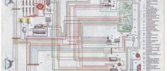
Electrical diagram of the T-25 tractor
1 — tractor front headlight FG 305; 2 - generator G302B alternating current 12 V 190 W; 3 - starter 12 V 2.8 l. With. ST222; 4 — battery 135 a*h 3-TST-135EMS; 5 — 47 kW plug socket; 6 — ground switch VK318B; 7 - turn signal relay RS410V; 8 — lamp holders for lighting devices PP102-Zh; 9 — electric lamp 12 V 1.5 sv; 10 — control element of heating PD51; 11 — oil pressure indicator MD219; 12— tachospeedometer with engine hour meter TX120; 13 — starter switch VK316B; 14 — indicator lamp PD-20-E; 15 — connecting panel 12-terminal PS 12; 16 — turn signal lamp 12 V 21 St; 17 — tractor front lamp PF204; 18 - electric lamp of size 12 in 6 units; 19 — brake light switch VKYU-B; 20 — tractor rear headlight FG304; 21 — tractor rear lamp FP209; 22 — wire connector PS305; 23 — electric lamp for brake light and clearance 12 V 21+6 light; 24 — signal button VK-34; 25 — headlight switch P57; 26 — direction indicator switch P57; 27 — plug connector; 28 — plug socket PSZOOA; 29 — electric lamp for license plate lighting 12 V 3 St; 30 — tractor license plate light FP200; 31 — indicator lamp PD20-D; 32 — rear headlight switch VK-57; 33 — size switch VK-57; 34 — ammeter AP200; 35 — oil temperature indicator UK 133M; 36 — control lamp holder PP113D; 37 — RS502 starter enable relay; 38 — additional resistance SE-52: 39 — 5-terminal connecting panel PS5; 40 — fuse block PR106; 41 — protection unit BZ-30; 42 — fuse-link PV-20A; 43 - blocking relay RB1; 44 — relay-regulator PP362B; 45 — glow plug CH150; 46 — sound signal C44; 47 — oil temperature sensor TM100; 48 - plug connector.
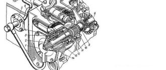
Gearbox of the T-25 tractor
1 – spacer sleeve; 2 – self-clamping oil seal; 3, 4 – ball bearings; 5 – gear of the second (fourth) gear A25.37.228 z=21; 6 – main gear housing A25.37.122; 7 – adjusting shims; 8 – bearing cup; 9 – ball bearing; 10 – spacer sleeve; 11 – protective cap; 12 – spacer sleeve; 13 – bearing sleeve; 14 – oil seal socket; 15 – ball bearing; 16 – splined bushing; 17 – cover 7.37.130-A; 18 – clip; 19 – constant mesh gear 25.37.156 z=25, z=19; 20 – third gear driven gear 7.37.120 z=36; 21 – bearing cup 7.37.141-1 right; 22 – high-speed gear 25.37.152 (ring z=59); 23 – final drive drive shaft; 24 – main shaft 25.37.157; 25 – movable doubler gear 25.37.155 z=19; 26 – ball bearing 214K3; 27 – support spherical washer; 28 – adjusting washers; 29 – differential axis 7.37.146-4; 30 – satellite 7.37.147; 31 – slow gear gear 7.37.144-2 (ring z=66); 32 – differential housing A25.37.150; 33 – bevel semi-axial gear 7.37.145 z=27; 34 – self-clamping oil seal; 35 – driven gear of the fifth (sixth) gear A25.37.154 z=27; 36 – clip 25.37.220; 37 – cover 7.37.123; 38 – ball bearing 5038; 39 – gear of the first (second) and slow gear 7.37.119 z=42; 40 – retaining ring; 41 – ball bearing 406; 42 – intermediate shaft 14.37.301-4; 43 – gear of first (third) and fifth (sixth) gears A25.37.229; 44 – reverse mechanism; 45 – drive gear transmission to the drive roller A25.37.259 z=13; 46 – adjusting shims; 47 – bearing cup; 48 – input shaft of gearbox 7.37.102-1; 49 – nut of the T-25 tractor.
The ability to move the moving gears of the gearbox is ensured by shift forks and a driver, which are attached to the shift rollers. The rollers are located above the gearbox shafts and move along bores made in the side walls of the main gear housing. The gear locking mechanism is designed to eliminate the possibility of turning off or on gears, as well as the reverse gear clutch, when the clutch is engaged. In addition, the locking mechanism prevents spontaneous switching off of reverse and gears when the unit is moving. Shifting gears, doubler and reverse occurs using a mechanism located in the top cover of the main gear.
Layout
The relative arrangement of the units of any tractor has historically developed a long time ago. The classic layout of a self-propelled vehicle is as follows: the engine is located in front, longitudinally, above the front axle. A gearbox is connected to it through the clutch, followed by a transfer case and followed by a drive axle. The shafts of the units are connected to each other using cardans and (or) couplings.
Following this scheme will be the best option when creating a mini tractor, because will allow you to use existing units without changing them. According to the experience of many creators of homemade tractors, it is better to assemble the units “in place”, without doing unnecessary drawings and calculations. The best option is to place all the main components and homemade mechanisms on the finished frame, installing them on temporary supports (conveniently, on wooden blocks), and, having found the best mutual position, make mounting brackets. But we must not forget that all components on a homemade tractor must be secured through supports that dampen vibrations (rubber cushions). It is best to borrow them from the same equipment from which the unit was taken. Another important factor needs to be taken into account. This is weight distribution, i.e. distribution of the total weight of the minitractor along the front and rear axles. The most acceptable option is that 60% of the weight falls on the drive wheels, 40% on the steering wheels.
Electrical diagram of the T-25 tractor
The electrical circuit of the T-25 tractor (Fig. 71) is single-wire, the nominal rectified voltage is 12 volts; The negative terminals of the current sources are connected to the body (“ground” of the tractor). Before starting the engine, use the ground switch 6 installed under the instrument panel to connect the negative terminal of the battery 4 to the tractor body. At the same time, control lamp 14 with a red cap lights up on the instrument panel. The engine is started by starter 3 with electromagnetic activation. The starter is turned on by turning the key inserted into the starter switch 13 through the intermediate relay 37.
The starter switch has two positions: the first is to turn on the heater 45 (glow plug) and the second is to turn on the starter. When starting the engine in winter, the duration of switching on the glow plug should be 30-40 seconds. The starter operation when starting the engine should not exceed 10 seconds. If the engine does not start after two or three starts with a minute break, then you should find out the reasons for the poor start and eliminate them. To automatically turn off the starter when starting the engine and eliminate the possibility of turning it on again when the engine is running, the electrical circuit is provided with a blocking relay 43. The battery is charged while the engine is running. In this case, DC voltage from the output terminals of the generator is supplied through ammeter 34 to the positive terminal of the battery. The negative terminal of the generator is connected to the tractor body by ground. The charging and discharging current of the battery is monitored by an ammeter.
Electrical diagram of the T-25 tractor
Rice. 71. Electrical diagram of the T-25 tractor: 1 — tractor front headlight FG 305; 2 - generator G302B alternating current 12 V 190 W; 3 - starter 12 V 2.8 l. With. ST222; 4 — battery 135 a*h 3-TST-135EMS; 5 — 47 kW plug socket; 6 — ground switch VK318B; 7 - turn signal relay RS410V; 8 — lamp holders for lighting devices PP102-Zh; 9 — electric lamp 12 V 1.5 sv; 10 — control element of heating PD51; 11 — oil pressure indicator MD219; 12— tachospeedometer with engine hour meter TX120; 13 — starter switch VK316B; 14 — indicator lamp PD-20-E; 15 — connecting panel 12-terminal PS 12; 16 — turn signal lamp 12 V 21 St; 17 — tractor front lamp PF204; 18 - electric lamp of size 12 in 6 units; 19 — brake light switch VKYU-B; 20 — tractor rear headlight FG304; 21 — tractor rear lamp FP209; 22 — wire connector PS305; 23 — electric lamp for brake light and clearance 12 V 21+6 light; 24 — signal button VK-34; 25 — headlight switch P57; 26 — direction indicator switch P57; 27 — plug connector; 28 — plug socket PSZOOA; 29 — electric lamp for license plate lighting 12 V 3 St; 30 — tractor license plate light FP200; 31 — indicator lamp PD20-D; 32 — rear headlight switch VK-57; 33 — size switch VK-57; 34 — ammeter AP200; 35 — oil temperature indicator UK 133M; 36 — control lamp holder PP113D; 37 — RS502 starter enable relay; 38 — additional resistance SE-52: 39 — 5-terminal connecting panel PS5; 40 — fuse block PR106; 41 — protection unit BZ-30; 42 — fuse-link PV-20A; 43 - blocking relay RB1; 44 — relay-regulator PP362B; 45 — glow plug CH150; 46 — sound signal C44; 47 — oil temperature sensor TM100; 48 - plug connector.
Electric current sources
There are two positions in this group:
- generator brand G302B, producing ~ I. The product has U=180 W. Equipped with a silicon rectifier. The latter has a contact-transistor type relay-regulator;
- a pair of 3TST135EMS brand batteries with a voltage of 6V and a capacity of 135 Ah each.
The generator solves the problem of generating electricity used to power all installed consumers of the tractor when the engine is running. If the latter is stopped, then power is supplied from batteries.
There are a number of operating modes when electricity consumption increases significantly (for example, transporting a loaded trailer in the dark with high beams and side lights on). In this case, power is provided in a combined mode, from the battery and the generator.
In normal operating modes, the generator’s performance is sufficient not only for consumers. The surplus is used to recharge tractor batteries.
Important! After stopping the engine, be sure to disconnect the negative terminal of the batteries from the housing. Otherwise, they may be completely discharged through the generator winding.
Figure 1 Electrical diagram
Electrical diagram of tractor t 25 color
SWITCH EQUIPMENT FOR TRACTOR T-25
Wires and electrical diagram of the T-25 tractor
All instruments and electrical equipment of the tractor are connected to each other by wires according to the circuit and installation diagrams.
The overwhelming number of wires are grouped into separate bundles with a common insulating tube and cotton braiding and laid along the engine spar under the floor, along the wing spars and under the wings.
Of great importance when operating a tractor is the ability to quickly disassemble the electrical equipment diagram and find the ends of the wires of one electrical circuit, as well as quickly and correctly connect the wires removed for inspection or repair to current sources and consumers. For this purpose, plug connectors are used on the generator and distribution box, and the wires have insulation of different colors.
For reference and guidance, see Fig. 91 shows the schematic and installation diagrams of the electrical equipment of the T-25 tractor.
Rice. 91. Electrical diagram of the T-25 tractor:
1 — tractor headlight (front) FG-30; 2 — electric lamps A12-50-21; 3 — generator G302B; 4 — starter ST-222; 5 — battery ZTST1E5EMS; c — ground switch VK-316B; 7 - socket; 8 — direction indicator breaker PC-410B; 9—additional resistance SE-52; 10— starter switch VK-316B; 11—connecting panel 12-terminal; 12 — indicator lamp PD-20E; 13 — electric lamp A12-1; 14 — heating control element PD-511 15 — oil pressure indicator MD-219; 16 — socket for instrument lighting lamp; 17 — electric lamp A12-1.5; 18 — light switch P-57; 19—front tractor lamp PF-204 right; 20 — electric lamp A12-21; 21—electric lamp A-12-21-6; 22 — wire connector IIC-305; 23 — tractor headlight (rear) FG-304; 24 — electric lamp A12-32; 25 — tractor rear lamp FP-209V right; 26 — electric lamp A12-21-6; 27 — turn switch 11-57; 28 — signal button VK-39; 29 — stop switch VK-10B; 30 — block; 31 — seven-pole socket PS-300A; 32 — tractor rear lamp FP-209 left; 33 — license plate light FN-2iO; 34 — electric lamp A12-3; 35 — left front tractor lamp PF-204B; 36 — tachospeedometer TX-120; 37 — ammeter AP-200; 38 — temperature indicator receiver UK-133; 39 — indicator lamp PD-20D; 40 — lamp socket for illuminating the tachometer speedometer; 41 — switch for lighting dimensions of the instrument panel and license plate VK-57; 42 — rear headlight switch VK-57; 43—starter relay; 44—5-terminal panel PS-5; 45 — fuse block PR-106; 46 — fuse BZ-ZO; 47—fuse link PV20A; 48 — blocking relay RB1; 49 — relay-regulator PP-362V; 50 - from the incandescent lamp CH-150; 51 — signal S-44; 52 — oil temperature sensor TM-100.
Mini tractor designs
For the most part, when making a tractor, amateur designers simply remake some serial product, adding some components and eliminating others. This is an easy way, but it is not always feasible, because... a complete machine must be available. And the design of homemade tractors created from scratch is individual in each case, so today the variety of solutions is simply off the charts. For example, the frame for a minitractor is made solid and breakable (called “fracture”), the rotation is made with steered wheels and onboard, the layout is classic or in the form of separate modules, allowing you to change the purpose of the device. Install the hydraulic system and power take-off shaft.
Tractor from the manufacturer at the price of a homemade product - the entire model range. We buy good attachments for a homemade agricultural machine using the link. Read in this article - the easiest way to assemble a mini tractor from a walk-behind tractor.
The homemade mini tractor offered below is one of the easiest to manufacture and allows you to get by with affordable materials and parts.
But, of course, anyone who is planning to do something themselves, with their own hands, is recommended to have technical skills, the ability to work with tools and read drawings. And, most importantly, have a lot of time and a great desire to do it.
Auto electrician
here you can download free electrical circuit diagrams for cars, tractors, and scooters. Alarms, manuals.
Electrical diagram of the T-25 tractor
Electrical diagram of the T-25 tractor
1 — tractor front headlight FG 305; 2 - generator G302B alternating current 12 V 190 W; 3 - starter 12 V 2.8 l. With. ST222; 4 — battery 135 a*h 3-TST-135EMS; 5 — 47 kW plug socket; 6 — ground switch VK318B; 7 - turn signal relay RS410V; 8 — lamp holders for lighting devices PP102-Zh; 9 — electric lamp 12 V 1.5 sv; 10 — control element of heating PD51; 11 — oil pressure indicator MD219; 12— tachospeedometer with engine hour meter TX120; 13 — starter switch VK316B; 14 — indicator lamp PD-20-E; 15 — connecting panel 12-terminal PS 12; 16 — turn signal lamp 12 V 21 St; 17 — tractor front lamp PF204; 18 - electric lamp of size 12 in 6 units; 19 — brake light switch VKYU-B; 20 — tractor rear headlight FG304; 21 — tractor rear lamp FP209; 22 — wire connector PS305; 23 — electric lamp for brake light and clearance 12 V 21+6 light; 24 — signal button VK-34; 25 — headlight switch P57; 26 — direction indicator switch P57; 27 — plug connector; 28 — plug socket PSZOOA; 29 — electric lamp for license plate lighting 12 V 3 St; 30 — tractor license plate light FP200; 31 — indicator lamp PD20-D; 32 — rear headlight switch VK-57; 33 — size switch VK-57; 34 — ammeter AP200; 35 — oil temperature indicator UK 133M; 36 — control lamp holder PP113D; 37 — RS502 starter enable relay; 38 — additional resistance SE-52: 39 — 5-terminal connecting panel PS5; 40 — fuse block PR106; 41 — protection unit BZ-30; 42 — fuse-link PV-20A; 43 - blocking relay RB1; 44 — relay-regulator PP362B; 45 — glow plug CH150; 46 — sound signal C44; 47 — oil temperature sensor TM100; 48 - plug connector.