Drilling operations require special equipment capable of operating in various, sometimes very difficult, conditions. In our country, equipment of both foreign and domestic production is available, and the latter is distinguished by its reliability, excellent technical characteristics and affordable price. The equipment produced by MOZBT JSC is characterized by high performance characteristics. The company has a full production cycle, so we can control the quality of every part. Quality is also guaranteed by testing all equipment at a special testing ground. Emergency service and technical support of the enterprise ensure the fulfillment of the manufacturer’s warranty obligations to the customer.
Purpose
URB 2A2 is designed to perform work for various purposes: drilling wells for geophysical research, blasting, drainage, injection, structural, prospecting, exploration, observation, geotechnical, gas, oil, water intake (including artesian) and other wells . This installation is capable of performing both vertical and inclined drilling, as well as screwing in piles for heat pumps. The rotator device allows for screwing and unscrewing of well strings, so that no additional tools are required for this purpose.
The URB 2A2 excavation of soil is carried out using the rotational method (auger, rotary or core). Its design makes it possible to quickly switch from one drilling method to another, as well as combine various methods (for example, auger with blowing).
Specifications
Drilling depth and diameter:
| Options | U measurement | Indicators |
| Drilling depth | m | |
| Structural wells with flushing | m | 300 |
| Geophysical wells | ||
| - with flushing | m | 100 |
| — with purging | m | 30 |
| — augers | m | 30 |
| Initial drilling diameter (with flushing) | mm | 190 |
| Final drilling diameter (with flushing) | ||
| — geophysical wells | mm | 118 |
| — structural prospecting wells | mm | 93 |
| Purge drilling diameter | mm | 118 |
| Auger drilling diameter | mm | 135 |
Characteristics of a movable type rotator with a stroke of 5200 mm.
| By rotation frequency | By moment | ||
| First speed | 140 rpm | 2010N/m | 205 kgf/m |
| Second speed | 225 rpm | 1210 N/m | 123 kgf/m |
| Third speed | 325 rpm | 830 N/m | 85 kgf/m |
Technical characteristics of the URB 2a2 drilling rig are presented in the table:
| Options | Unit measurements | Indicators |
| Rotator drive | ||
| Type | axial piston | |
| Slave. hydraulic pressure | MPa | 980 |
| kgf/cm2 | 100 | |
| Tool lowering/feeding/lifting mechanism | ||
| Jack with polyplate system | hydraulic | |
| Load capacity | N | 45 |
| kgf | 4600 | |
| Downward force (at a pressure of 85 kgf/cm2) | N | 25500 |
| Lifting speed | m/sec | 0-1,1 |
| Drill pipes | ||
| Diameter | mm | 50 (60,3) |
| Length | mm | 4500 |
| Mast | ||
| Type | Welded with hydraulic jacks | |
| Load capacity | N | 58800 |
| kgf | 6000 | |
| Compressor | ||
| Type | KSBU-4VU1-5/9 | |
| Max. performance | m3/min | 10 (±0,5) |
| Pressure (nominal, gauge, outlet) | MPa | 0,8 |
| kgf/cm2 | 8 | |
| Mud pump | ||
| Type | NB-32 | |
| Innings | ||
| — with a piston with a diameter of 100 mm | m3/hour | not less than 26.3 |
| — with a piston with a diameter of 110 mm | m3/hour | not less than 32.4 |
| Outlet pressure (highest) | ||
| — with a piston with a diameter of 100 mm | IPA | not less than 3.2 |
| — with a piston with a diameter of 110 mm | MPa | not less than 2.6 |
Video review of the URB 2a2 drilling rig:
Description of URB 2A2
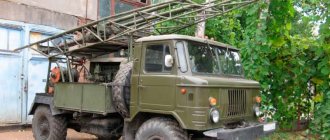
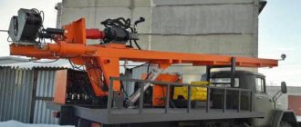
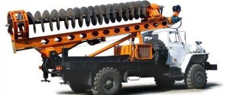
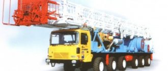
Structurally, these models of installations consist of a rotator, a transfer case, a mast and a mud pump or compressor. All equipment is mounted on an all-terrain transport base on wheels: ZIL, URAL or KAMAZ; or on crawler tracks: TLT-100, TT-4M, MTLBu. Extraction of destroyed rock to the surface is carried out by rotating augers, or by washing or blowing the bottom of the well. The moving units are equipped with a hydraulic drive, which is controlled by the operator’s console. The hydraulic drive of the rotator makes it possible to lift, lower and feed the drilling tool, and also allows you to extend the drill string without detaching it from the wellbore.
Thanks to the all-terrain wheeled chassis, as well as the caterpillar track, which is equipped with some models, it can be carried out in hard-to-reach places and on difficult soils.
Device
As standard, the URB-2A2 is mounted on a reinforced supporting frame, which is installed on the basis of the improved ZIL-131. It has increased maneuverability, which is suitable for any exploration and drilling conditions.
Thanks to the moving rotator, which is equipped with a hydraulic drive, it is possible to:
- raising and lowering drilling tools;
- increasing length without separation from the face;
- improvement of drilling quality.
Thanks to the hydraulic drive, all work is greatly facilitated. It is controlled from the driller's console, which provides sensitive regulation and efficient drilling.
The kinematic system is implemented through the ZIL-131 engine using:
- mud pump NB-50, pumps MN250/100 and NSh-10-EL;
- compressor, hydraulic motor and rotator;
- gearboxes and transfer case, as well as power take-off and the transfer case itself.
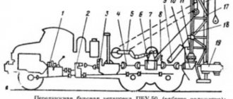
Kinematic diagram of the URB 2a2 drilling rig
The rotator moves along the mast thanks to the traveling system and hydraulic drive.
Pressure gauges are installed in the hydraulic system to ensure optimal drilling conditions. Thanks to the filters, the oil is cleaned, which extends its service life significantly. Equipping with an emergency hand pump makes it possible to manually turn off the installation if the vehicle fails. Tool lifting is possible in emergency, slow, fast and normal modes. The instrument can be hung in any of the elevated positions. The support jacks extend. The descent of the tool can be either fast or normal. A simple and reliable hydraulic system allows full control without problems.
The power take-off has one gear (mechanical and with a clutch). It is fixed in the upper part of the housing of the ZIL-131 transfer box itself. The transfer case of the installation itself is switched on through the cardan shaft and power take-off. Thanks to this box, rotation is transmitted to both the drilling pump and the oil pumps.
The rotator is represented by a three-shaft gearbox with three speeds and cylindrical and gear transmissions.
It is housed in a cast steel housing, which guarantees better reliability. On the remote control you can adjust the spindle speed - from zero to maximum. Spindle-type rotator circuit
Due to the fact that the feed hydraulic jack consists of a rod and a cylindrical part, the latter takes on part of the rotational reactive load. It has one double acting stage. The mast itself is U-shaped from channels with additional transverse beams. Inside there is not only a hydraulic jack, but also 2 pipes that take on the load. This rigid design gives better drilling performance even in difficult conditions. The presence of a centering table makes it easier to use the drilling tool.
The traveling system makes it possible to double the rotator stroke and has a reliable and simple design (two ropes and 2 tensioning devices).
The elevator makes it possible to make up/unscrew pipes for drilling and lowering/lifting tools. It is easy to operate thanks to high-quality mounting and design. Auger chucks allow you to extend and lift augers in a safe manner and guarantee the quality of auger drilling.
Thanks to the rotator movement mechanism (hydraulic jack plus polyplate system), double movement speed is ensured. The mast is automatically moved to the transport position if the transmission or drive motor breaks down. Support jacks automatically unload the ZIL-131 chassis when lifting the tool.
Purchase of URB 2A2
You can buy a URB 2A2 drilling rig with the parameters you need on our website using the configuration configurator. We can manufacture equipment based on your requirements and specific operating conditions. The work is carried out on a turnkey basis so that in the end you receive a device completely ready for use.
The price for URB 2A2 depends on the configuration you choose and is calculated individually. Purchasing equipment from JSC “MOZBT” is also profitable because the kit includes a rich set of spare parts, and this significantly reduces the cost and facilitates the process of maintenance and repair in the field. Extensive experience in production allows JSC "MOZBT" to produce reliable and easy-to-use equipment that fully justifies the investment with a long period of trouble-free operation.
Manufacturers
- Drilling equipment plant
- Vorovsky Plant
- ZBM (Ekaterinburg)
- MOZBT
- Spetsburmash
- UralSpetsAvto
- Innkor
- Gemmash
Manufacturers of URB drilling rigs
Drilling rig URB 2A2D
Preparation of the installation for drilling should be carried out on a leveled site. Before starting work, you should make sure that there is oil in the crankcases of the mechanisms and the hydraulic system tank of the unit. After this, you should open the oil tank tap and, with the engine clutch disengaged, turn on the transfer case. Before lifting the mast, it is necessary to loosen its attachment to the front support, and then bleed the mast lift cylinder to remove air from it. To do this, you need to raise the mast 30 - 40° and lower it.
The mast is raised from the NSh-10L pump by turning on the feed distributor to the “down” position, and the mast lift distributor to the “lift” position. In this case, the supply regulator must be open, and the pressure regulator must be closed.
Once the mast reaches a vertical position, lower the lift spool handle and it will automatically move to the neutral position. The mast in a vertical position is secured with clamps to the frame of the drilling rig .
When raising the mast, the pressure in the hydraulic system should not exceed 6.5 MPa (65 kgf/cm2).
After lifting the mast and securing it to the installation frame, the support jacks are extended until they come into contact with the ground or with special wooden stands. To do this, it is necessary to bring the rotator up to the stop in the normal operating mode of the feed hydraulic cylinder and open both valves on the mast. After extending the jack rods to the required amount, close the valves.
To make it easier to control the installation, a special wooden stand is placed under your feet near the remote control. Preparing the drilling rig for transportation is carried out in the reverse order.
Drilling wells with bottom hole flushing
When drilling with flushing the bottom, four bolts are unscrewed from below at the liner installed in the mast table and the casing for the augers and the centralizer for the pipes are removed. The desired gear in the rotator is engaged. A drill pipe lock with an adapter and a bit screwed onto it is placed in the elevator. After this, the rotator with the pipe rises above the mast table, the pipe is directed into the hole in the liner and lowered until it comes into contact with the ground. Then the elevator fitting is directed into the pipe coupling and, by turning the rotator spindle, is screwed into the pipe.
Two halves of a pipe centralizer are installed into the liner on top. The engine friction clutch is turned off, then the drilling pump is turned on, the friction clutch is turned on, the rotation speed of the rotator spindle is gradually increased to the maximum and the desired feed rate is set using the feed regulator.
Having passed the well to the depth of the pipe, the flushing pump and rotator stop, and the supply stops. The pipe centralizer is removed from the liner.
A fork is inserted into the slot of the pipe lock, which stops the pipe, and by turning on the left rotation, the connection between the elevator fitting and the pipe is unscrewed. Then the elevator gate opens and the rotator rises slightly.
The lock of the subsequent pipe is grabbed by the elevator and the pipe is lifted. The elevator fitting and the lower end of the pipe are either together or separately inserted into the pipe couplings and screwed into them. So the entire drilling process continues with the above-described cyclicity to the required depth. The process of lifting the pipes occurs in the reverse order. The pipe column is suspended on the table on a fork and the connection between the elevator fitting and the pipe is unscrewed. Then the pipe column is lifted, the fork is inserted into the lower slot of the upper lock of the subsequent pipe and the connection is unscrewed. The pipe is lowered and removed from the elevator.
When drilling with flushing, the pipe centralizer can be secured to the liner from below using four bolts. In this case, as well as in the case when the diameter of the bit exceeds the diameter of the liner hole, before drilling , the liner is put on the drill pipe from the upper end with the adapter and bit turned onto it. Then the drill pipe lock is placed in the elevator, the pipe is lifted, a bit is inserted into the hole in the mast table and the liner is secured in the mast table using a clamp.
Drilling with air blowing
Before starting drilling wells with air blowing, it is necessary to mount the distributor using a three-way valve from the NB-50 drilling pump. Then the sealer body is installed in the guides of the mast table, a vortex pump with a dust removal sleeve is attached to it, and a sleeve from the distributor is attached to the vortex pump to supply compressed air.
When drilling with an air hammer, a mud protection device is installed above it and its operation on the surface is checked. The valve on the distributor regulates the ratio of air flow to the hammer and the vortex pump so that with the nominal performance of the compressors and the hammer operating, the air pressure is at least 0.5 MPa (5 kgf/cm2). To launch the air hammer, an axial load of at least 1.50 kN (150 kgf) is applied to it. After drilling the well , the interval of loose sediments is secured with casing pipes. If there is no need to secure the well walls, a pipe is installed to prevent sludge particles from falling back into the well.
After lowering the tool into the well, valves and collars are inserted between the seal body and the mast table.
Recommended parameters for the air percussion drilling process:
- rotation speed from 15 to 60 rpm. (lower rotation speed for harder rocks);
- axial load from 100 to 250 kgf (higher values for rocks of drillability categories V – VI).
During the drilling of flooded wells, especially at air temperatures below 0°C, the vortex pump with a dust removal hose and the curtain are disconnected from the housing. When lowering a projectile into a flooded well, it is recommended to periodically supply air into it to lower the water level. When expanding the projectile, the supply of compressed air into the well is stopped by switching the three-way valve of the distributor.
At the end of the drilling , the valves and collars are removed and the tool is raised in the usual sequence.
Drilling with augers
When drilling with augers, the sealer is dismantled and the casing for the augers is attached to the mast table liner from below using four bolts.
When the rotator is in the lower position, a cartridge for augers is secured in the elevator, and an auger with a chisel is secured in the cartridge. The required gear in the rotator is engaged. The rotator and auger are raised above the table, the auger is directed into the hole in the liner and lowered all the way into the ground.
The elevator fitting fits into the thread of the cartridge adapter. The rotation starts smoothly, and after screwing the fitting into the adapter, the required pressure on the bottom is set.
After drilling the hole to the depth of the auger, a shim fork and a cartridge are inserted into the slot of the auger cartridge adapter; The connection between the elevator fitting and the cartridge adapter is locked and unscrewed. The auger is disconnected from the cartridge, to which the next auger is connected and the operations described above are repeated.
Maintenance of the drilling rig ensures constant readiness for operation and operational safety; eliminating the causes of premature wear, malfunction and breakdown of components and mechanisms, extending turnaround time, minimal consumption of oil, fuel, lubricants and operating materials.
The frequency of maintenance of the drilling rig must be observed under any operating conditions and at any time of the year. Maintenance of the installation is carried out simultaneously with the regular maintenance of components in accordance with the requirements set out in their operational documentation.
When carrying out maintenance, personnel must undergo safety training. Repair of the installation equipment should be carried out only after stopping the engine in the absence of pressure in the units being repaired and draining the process fluid. When performing welding work, the safety requirements in accordance with GOST 12.3.002-75, GOST 12.3.003-86 must be observed. Welding must be carried out by a welder who has a certificate to perform such work.
Maintenance Procedure
The reliability of the installation depends on proper operation and careful maintenance.
The driver and driller are required to monitor the proper operation of all mechanisms and components of the installation. If abnormal operation of mechanisms is detected, extraneous noise, knocking or vibration appears, as well as if adjustments are violated, the driller is obliged to immediately, without waiting for the next maintenance period, take measures to eliminate them. Current repairs of the drilling rig
Current repairs (RM) are carried out during operation to maintain the operability of the installation. Current repairs include the following work:
- partial development of the mud pump, transfer case and rotator;
- condition check, repair of pumps and gears;
- checking the condition, replacing or repairing gears, fastening and locking parts, seals, gaskets when worn, adjusting rolling bearings, replacing plain bearings (liners);
- replacement and repair of pipes, valves, taps, articulated elbows, hoses and drive belts in the presence of wear, cracks, chips, bent and flattened areas;
- replacement of cardan shaft forks and crosspieces if there is wear;
- replacement of worn couplings and connecting flanges;
- checking the condition and replacing safety and check valves on the pump discharge line;
- replacement of worn springs, valve seats and valves, filling line valves;
- repair of the oil block in the presence of cracks and dents;
- checking and replacing faulty instrumentation;
- replacement and repair of the gear pump, plunger pump lubrication system, oil lines in the presence of wear, leaks or other defects;
- checking the tightness of the main line, replacing worn sealing elements;
- replacing the lubricant in all units of the installation in accordance with the lubrication chart;
- assembly, adjustment and testing of the installation, hydraulic testing of pumps and piping (pipelines).
Overhaul (CR)
Major repairs are carried out in order to restore the operability of the installation. During major repairs, complete disassembly of the installation equipment, washing and defect detection of parts and assemblies, repair, assembly, adjustment, load testing and painting are carried out.
Major repairs, as a rule, are carried out at a central production service base and at specialized mechanical repair plants. The equipment is sent to the Kyrgyz Republic in accordance with the preventive maintenance schedule together with a defect report.
During a major overhaul, a complete disassembly and inspection of the condition of pump parts is also carried out (in accordance with the operational documentation).
All bolts and nuts of installation components and mechanisms must be protected from loosening during assembly and installation.
Equipment lubrication
Correct and regular lubrication with appropriate grades of oils and lubricants protects installation components and mechanisms from premature wear and increases the service life of equipment.
Major problems in the operation of the URB 2A2D drilling rig can occur mainly due to a malfunction of the hydraulic system. Possible malfunctions of the installation's hydraulic system, causes and methods for eliminating them are given in Table 3.
Table 3 - Possible hydraulic system malfunctions
| Malfunctions | Causes | Remedies |
| 1 | 2 | 3 |
| Bearings overheat | 1. No or insufficient lubrication 2. Contaminated lubrication 3 Over-tightened bearings | 1. Add grease to the required level 2. Replace the grease 3. Adjust the axial clearances of the bearings, achieve free rotation of the shaft without feeling any play |
| There is no pressure in the hydraulic system | 1. The suction valve of the hydraulic pumps is closed. 2. There is not enough oil in the tank. | 1. Open the tap. 2. Add oil to normal level |
| Pump N1 (NSH-10L) (see Fig. 3) does not create pressure | 1. Valve VN1 (supply regulator) or VN 7 (pressure regulator) is open 2. Safety valve KP1 is clogged 3. Check valve K03 is clogged | 1. Close the valve 2. Disassemble and wash the valve (see clause 1.2.14.3) 3. Disassemble and wash the valve (see clause 1.2.14.1) |
| Pump N1 (NSH-10L) creates pressure only at high speeds | 1. The overflow valve of the safety valve KP1 is clogged 2. The pump is out of order | 1. Remove the control valve, remove the spring and plunger of the main valve, wash the valve seat and plunger with a stream of working fluid 2. Replace the pump |
| Pump N1 (NSH-10L) does not create pressure or creates it only at high speeds. When the rotator is brought to the stop and pressure is created in one of the cavities of the hydraulic cylinder using pump H5, the pressure quickly drops after the pump is turned off | 1. Check valve K03 (G51-35) is clogged 2. The cuffs on the hydraulic cylinder piston are worn out 3. Valve VN1 (feed regulator) does not close completely | 1. Unscrew the plug, remove the spring and valve, wash the valve seat and valve with a stream of working fluid. 2. Disassemble the cylinder and replace the cuffs. 3. Replace the valve |
| Pump H5 does not create pressure | 1. Safety valve KP3 is clogged 2. Oil flow through valve VN3 3. Pump is faulty 4 Check valve KO1 is clogged | 1. Disassemble and wash the valve 2. Replace the valve 3. Replace the pump 4. Disassemble and wash the valve |
| Pump H4 does not create pressure | 1. Safety valve KP2 is clogged 2. Oil flow through valve VN2 3. Check valve KO5 is clogged | 1. Disassemble and wash the valve 2. Replace the valve 3. Disassemble and wash the valve |
| Pump H3 does not create pressure | 1. Safety valve KP4 is clogged 2. Oil flow through valve VN6 3 Check valve K04 is clogged 4. Pump is faulty | 1. Disassemble and wash the valve 2. Replace the valve 3. Disassemble and wash the valve 4. Replace the pump |
| The rotator does not provide maximum torque, the oil in the hydraulic system quickly overheats, a large amount of oil enters through the drain hoses of the H4 pump or the M hydraulic motor | 1. Pump or hydraulic motor is faulty | 1. Replace the pump or hydraulic motor |
| Noise during pump operation, oil emulsification, excessive foaming | 1. Insufficient oil level in the tank 2. Air leaks at the connections on the suction line | 1. Add oil to normal level 2. Tighten connections or replace hoses |
| Frequent clogging of safety valves, increased wear of pumps and hydraulic motors | 1. The oil in the hydraulic system is contaminated. | 1. Replace dirty filter elements. If there is a large amount of sediment in the oil tank, drain the oil and flush the oil tank. Fill the oil through a cambric or similar cloth filter |
Drilling wells with a small-sized installation
The drilling rig requires a certain amount of space due to its size. Therefore, there are often strict requirements for the width of the entrance gate and road. Also, the free area must be at least 4x12 m.
In practice, compliance with such strict conditions is impossible for various reasons. This may be due to the small size of the site itself, due to development or landscape features. What to do?
In this case, drilling can be carried out using small-sized equipment.
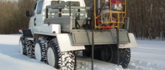
Look at real photos from the drilling site using standard equipment and a small-sized rig.
began using the Zhuravl installation in 2014. Demand exceeded supply, so it increased production capacity using another KZBT drilling rig with similar technical parameters. Compare photographs of the Zhuravl and KZBT machines.
Advantages of a small installation:
- Possibility of drilling in difficult conditions
- Entry requirements are the same as for passenger cars.
- Minimal damage to the site compared to a standard installation due to lower weight and crawler tracks of the installations
- Possibility of well repair if after drilling the well the area is built up and a conventional installation will not fit in
- The drilling rig is accompanied by a water carrier based on ZIL 131 and a shelter for the crew to live in; they do not need to enter the site, as in the case of drilling with standard equipment
If there are restrictions due to the height of the canopy, then the height of the “Crane” machine is 2.7 meters, and the KZBT is 2.3 meters, that is, in this case, the KZBT is preferable.
Features of drilling with small-sized equipment:
- The installation is compact, shorter pipe lengths are used, correspondingly more threaded connections and, as a result, higher cost of casing pipes
- The length of the drill rods is shorter, which means more labor operations, and this increases the duration of work
- Lower unit power increases drilling time
- The installation is delivered using trucks or a manipulator is used
- Depth limitation (only for some areas), drilling possible to a depth of up to 120 m
For these reasons, the use of a small rig results in increased drilling costs, but the obvious benefits of using such equipment justify these costs.
In any case, to make the right choice, order a preliminary visit to the drilling site by a specialist.
Yes, but less rigid, the width of the machine is 1.5 meters. A drive designed for a passenger car is suitable. If entry to the site must be done through an arch or canopy, then the height must be at least 2.4 meters.
If drilling with a small-sized rig is so attractive, then why do they offer a standard one in the first place?
Because the cost of drilling a small well is somewhat more expensive. If it is possible to bring in heavy equipment, there is no reason to overpay. And due to restrictions on the depth of the well - no more than 120 m.