The device of the DT-75 carriage
The main working elements of the DT-75 suspension carriage are external and internal balancers, four road wheels and a shock-absorbing device in the form of a spring. The suspension balancers are pivotally connected to each other. The common hollow axis of the DT-75 carriage is mounted in bushings. To prevent rotation during operation, it is tightly fixed in the internal balancer. To increase operational reliability, the carriage device includes an additional solid axis. It is inserted inside the hollow axis of the balancers and mounted on bushings. There are sealing covers installed on both sides that protect the hinge joint of the balancers from the ingress of abrasive substances (dirt, dust and moisture).
On the lower castings of the housing of both balancers, seats for bearings are bored out. The bearing units of the axles of the carriage support rollers are mounted here. The bearings are protected on both sides by a cover with a seal. At the top of the balancers, mounting spots for the shock-absorbing spring are cast.
Diagram of the DT-75 suspension carriage
| № | Name | Catalog number | Quantity per model |
| Suspension carriage front right and rear left | 85.31.001-1 | 2 | |
| Heat-treated cylindrical pin 5Pr22aKh10, GOST 3128-60 | — | 4 | |
| 1 | Nut M16X15, GOST 5927-62 | — | 4 |
| 7 | External balancer | 85.31.101 | 4 |
| 11 | Bolt М12Х30, GOST 7796-62 | — | 96 |
| 12 | Spring washer 12N, GOST 6402-61 | — | 32 |
| 13 | Threaded plug RKII-3/8″, GOST 3112-54 | — | 16 |
| 14 | Spring | 85.31.112 | 4 |
| 17 | Non-standard tapered roller bearing | 7909M (47Х100Х43) | 16 |
| 18 | Roller axle | 54.31.402A | 8 |
| 21 | Ring | 54.31.473-1 | 16 |
| 26 | Seal cover | 54.31.409-1A | 16 |
| 33 | Ordinary prismatic key B10Х8Х70, GOST 8789-58 | — | 16 |
| 34 | Adjustment spacer (0.4 mm) | 54.31.406 | 32 |
| 44 | Semi-coarse-haired seal ring, GOST 6308-61 | — | 4 |
| 45 | Remote ring | 77.31.106 | 4 |
| 46 | Reinforced rubber cuff MN 5308-64 | — | 4 |
| 47 | Seal body | 77.31.105-2 | 4 |
| 52 | Nut M27X1.5, GOST 5916-62 | — | 8 |
| 54 | Swing axis | 54.31.415-1 | 4 |
| 55 | Lid | 85.31.115 | 4 |
| 56 | Balancer internal | 85.31.102-1 | 4 |
Not available:
| № | Part code | Name | Part Information |
| 85-31-001-1 | Suspension carriage front right and rear left | Quantity for DT-75MV 2 Weight Material 149.29 | Not available |
| 85-31-002-1 | Suspension carriage front left and rear right | Quantity for DT-75MV 2 Weight Material 149.29 | Not available |
| 85-31-020 | Installing the footrest | Quantity for DT-75MV 1 Weight Material 2.24 | Not available |
| 85-31-128A | Bolt | Quantity per DT-75MV 1 | Not available |
| Nut-M20x-1.5-8-01-6-GOST-5915-70 | Nut M20x 1.5-8.01 6 GOST 5915-70 | Quantity per DT-75MV 1 | Not available |
| Washer-2065G05-GOST-6402-70 | Washer 2065G05 GOST 6402-70 | Quantity per DT-75MV 1 Note 2 | Not available |
| 54-31-021I | Track roller | Quantity for DT-75MV 4 Weight Material 14,993 | Not available |
| 85-31-144 | Ring | Quantity per DT-75MV 4 | Not available |
| 54-31-478 | Washer | Quantity per DT-75MV 4 | Not available |
| 85-31-120 | Lock washer | Quantity per DT-75MV 4 | Not available |
| А31-3-01А | Roller axle nut | Quantity per DT-75MV 4 | Not available |
| Stopper-2-1MK16,10kl-06-GOST-12717-78 | Plug 2-1MK16, 10kl.06 GOST 12717-78 | Quantity per DT-75MV 4 | Not available |
| 77-31-103A | Lid | Quantity for DT-75MV 1 Weight Material 1.6 | Not available |
| 77-31-104 | Pad | Quantity per DT-75MV 1 | Not available |
| Bolt-M16x1.5x65-88-35-016-GOST-7796-70 | Bolt M16x1.5x65.88.35.016 GOST 7796-70 | Quantity per DT-75MV 1 | Not available |
| Washer-16-65G-05-GOST-6402-70 | Washer 16 65G 05 GOST 6402-70 | Quantity per DT-75MV 1 | Not available |
| 77-31-118 | Collet nut | Quantity per DT-75MV 1 | Not available |
| 77-31-116-3 | Tapered bushing | Quantity per DT-75MV 1 | Not available |
| 77-31-014-1Р | Conical bushing assembled with bolt | Quantity per DT-75MV 1 | Not available |
| 85-31-017 | Collet nut | Quantity per DT-75MV 1 | Not available |
| Nut-M30x2-6N-8-016-GOST-15522-70 | Nut M30x2.6N.8.016 GOST 15522-70 | Quantity per DT-75MV 1 | Not available |
| Washer-30-65G-05-GOST-6402-70 | Washer 30 65G 05 GOST 6402-70 | Quantity per DT-75MV 1 | Not available |
| 85-31-124 | Lid | Quantity per DT-75MV 1 | Not available |
| 85-31-102-1 | Balancer internal | Quantity for DT-75MV 1 Weight Material 16.57 | Not available |
| 85-31-011-1 | External balancer assembly | Quantity for DT-75MV 1 Weight Material 34.9 | Not available |
| 77-30-133-1 | Bushing small | Quantity per DT-75MV 2 | Not available |
| 7731-111A | Sleeve | Quantity per DT-75MV 2 | Not available |
| 85-31-101 | External balancer | Quantity for DT-75MV 1 Weight Material 28.6 | Not available |
| Stopper-3-MK16-A12-06-GOST-12717-78 | Plug 3-MK16.A12.06 GOST 12717-78 | Quantity per DT-75MV 1 | Not available |
| 85-31-112 | Spring | Quantity for DT-75MV 1 Weight Material 17.41 | Not available |
| 85-31-012-1Р | Wedge | Quantity per DT-75MV 1 | Not available |
| 85-31-107-1 | Wedge | Not available | |
| Washer-22-65G-05-GOST-6402-70 | Washer 22 65G 05 GOST 6402-70 | Quantity per DT-75MV 1 | Not available |
| 85-31-110-2 | screw | Quantity per DT-75MV 1 | Not available |
| 85-31-117 | Swing axis | Quantity for DT-75MV 1 Weight Material 2.32 | Not available |
| 85-31-016A | Axis | Quantity for DT-75MV 1 Weight Material 2.15 | Not available |
| Bolt-М12-6gх30-58-016-GOST-7796-70 | Bolt М12.6gх30.58.016 GOST 7796-70 | Quantity for DT-75MV 20 | Not available |
| Washer-1265G05-GOST-6402-70 | Washer 1265G05 GOST 6402-70 | Quantity for DT-75MV 24 | Not available |
| 54-31-025 | Seal cover assembly | Quantity per DT-75MV 4 | Not available |
| 54-31-409-1B | Seal cover | Quantity per DT-75MV 1 | Not available |
| 54-31-464-1A | Pressure washer | Quantity per DT-75MV 2 | Not available |
| 54-31-023 | Seal spring assembly | Quantity per DT-75MV 1 | Not available |
| 54-31-430 | Small o-ring | Quantity per DT-75MV 4 | Not available |
| 54-31-472 | Retaining ring | Quantity per DT-75MV 4 | Not available |
| 54-31-022-1 | Seal housing assembly | Quantity for DT-75MV 4 Weight Material 1,112 | Not available |
| 54-31-473 | Ring | Quantity per DT-75MV 1 | Not available |
| 54-31-463-2 | Ring sealing | Quantity per DT-75MV 1 | Not available |
| 54-31-405-2 | External seal housing | Quantity per DT-75MV 1 | Not available |
| 54-31-445 | Adjustment spacer (0.2 mm) | Quantity on DT-75MV 8 | Not available |
| 54-31-444 | Adjustment spacer (0.6 mm) | Quantity for DT-75MV 12 | Not available |
| 54-31-406 | Adjustment spacer (0.4 mm) | Quantity on DT-75MV 8 | Not available |
| Key-2-10x8x70-GOST-23360-78 | Key 2-10x8x70 GOST 23360-78 | Quantity per DT-75MV 4 | Not available |
| 54-31-474-2 | Ring | Quantity per DT-75MV 4 | Not available |
| Roller bearing-7909M-(47x100-43)-(non-standard) | Roller bearing 7909M (47x100-43) (non-standard) | Quantity for DT-75MV 4 Weight Material 1.6 | Not available |
| 85-31-119A | Roller axle | Quantity for DT-75MV 2 Weight Material 3.62 | Not available |
| 112-31-029 | Seal | Quantity per DT-75MV 1 | Not available |
| Т24-4612055 | Ring sealing | Quantity for DT-75MV 1 Model T24 Subgroup 4612 Part number 055 | Not available |
| 85-31-031 | Step | Quantity per DT-75MV 1 | Not available |
| 85-31-130 | Leading clip | Quantity per DT-75MV 1 | Not available |
| 85-31-023 | Case | Quantity per DT-75MV 1 | Not available |
| 85-31-131 | External clip | Quantity per DT-75MV 1 | Not available |
| 77-30-131-1 | Protective ring | Quantity per DT-75MV 4 | Not available |
| Bolt-М12-6gх25-58-016-GOST-7796-70 | Bolt М12.6gх25.58.016 GOST 7796-70 | Quantity per DT-75MV 4 | Not available |
| 77-31-107-1 | Washer | Not available |
Adjustments of the DT-75 carriage
To maintain efficient and long-term operation of the DT-75 suspension carriages, their condition and various settings are periodically checked.
- The axial play in the bearing assembly is adjusted. The permissible axial movement should be 0.2-0.4 mm. To perform this operation, it is necessary to install a jack under the beam of the corresponding carriage and lift it until the spring spring is completely freed from the load.
- Axial play and radial runout of the support rollers of the DT-75 carriage. The roller supports with the hub are hingedly mounted on the bracket necks. The axles are secured to the supports with pins against rotation. To determine the backlash, a crowbar is used, passed through the window of the skating rink. By placing it on the balancer, pressure is exerted on the support roller in the radial and axial directions. If the amount of play in the bearings of the roller axle is greater than permissible, it is necessary to adjust it. It works like this:
- It is necessary to remove the DT-75 carriage from the axle.
- After unscrewing the fastening nuts, use a puller to pull the rollers from the axle.
- Next, remove the seal housing and shims. Axial play in the bearing assembly is controlled by reducing the number of spacers. It is necessary to achieve the result that the bearings rotate freely and without jamming after tightening the seal cover.
- On the axle suspension axles, the axial play is not adjusted. But to determine the degree of wear of parts, it is necessary to check the axial movement, the condition of fasteners and threaded connections. When a movement of more than 2 mm is achieved, it is necessary to install another one instead of the factory one, which reduces the axial movement of the suspension carriage in the trunnion to the recommended limits of 0.5-2 mm.
- To prevent jamming of the minor swing axis, before operating the tractor, it is necessary to disassemble the unit and clean it of cementing dust and dirt, thoroughly wash all parts with kerosene and lubricate it with transmission oil.
Maintenance of DT-75 carriages during operation
During operation of the DT-75 tractor, constant monitoring of all parts of the chassis is required. It is necessary to eliminate the cause of lubricant leakage, tighten threaded connections, make adjustments and add lubricant to the bearing units of guide wheels, carriages and support rollers. And although the price for the DT-75 carriage remains within reasonable limits, you should take timely care of its performance. For quality service, you can use a special repair kit for the DT-75 carriage.
Mandatory and complete maintenance of DT-75 carriages and other components increases the reliability of the tractor chassis.
Rating: 4.8/5 — 14 votes
Chassis of the DT-75 tractor
The chassis serves to convert the rotational motion of the final drive gear into forward motion of the tractor. At the same time, it provides support for the tractor body and provides the necessary adhesion to the soil.
The chassis of the DT-75 tractor consists of a suspension, guide wheels with spring shock absorbers, support rollers and tracks. A suspension is a device with which the tractor body rests on rollers that roll along the caterpillar. Depending on the suspension design, the support rollers can be sprung and move relative to the factor housing, or unsprung and have no movement. On this basis, pendants are divided into elastic, rigid and semi-rigid. The DT-75 tractor uses an elastic balancing suspension. This suspension provides better ride comfort, especially when working at high speeds with mounted agricultural implements. The suspension is made using four identical balancing carriages mounted on frame axles in pairs on each side of the tractor.
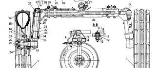
The suspension carriage is a trolley consisting of two balancers, external / (Fig. 75) and internal 5. The balancers are pivotally connected to each other by their upper ends using a swing axis 10. At the lower ends of the balancers, support rollers 4 are mounted in pairs. In the upper part there are balancers are bursting with a cylindrical spring-spring 3, which at one end is inserted into the cup of the external balancer, and the other is mounted on the pin of the upper head of the internal balancer.
To provide the necessary strength, the balancers are cast from steel and have a closed box-shaped section. The external balancer with a central hole with hardened steel bushings 17 pressed into it is freely mounted on the axle 18 of the frame transverse beam. With this arrangement of carriages, the weight of the tractor body, perceived by the road wheels, is balanced by the elastic force of the springs compressed by the upper heads of the balancers. Thanks to their elasticity, the springs help soften the shocks transmitted to the tractor body when moving over uneven soil. The suspension carriage is kept from moving to the outer side of the tractor on the frame axle by an annular thrust washer 13, pressed to the end of the axle by a collet nut 14, screwed into the internal threaded hole of the axle. As can be seen from Figure 76, in which the axial fastening parts are shown disassembled, the annular thrust washer 2 has, on the inner diameter with which it is centered on the trunnion protrusion /, two teeth that fit tightly into the grooves of the protrusion. Therefore, the rocking of the balancer on the trunnion is not transmitted to the collet nut, which increases the reliability of fastening the carriage to the frame.
1 — external balancer; 2 — filler plug; 3 — spring (spring); 4 — support roller: 5 — internal balancer; b - prefabricated wedge; 7 - cover; 8 - bolt; 9 - nut; w swing axis; 11 - axis bushing. rocking; 12 - cover; 13 — thrust washer; 14—assembled collet nut; 15 — oil control hole plug; 16 — gasket; 17 — trunnion bushing; 18 — axle; 19 - plug; 20 — seal housing; 21 - outer ring. The collet nut 5 on the threaded shank, which is screwed into the trunnion, has a through slot and an internal conical hole into which the conical head of the spacer bolt 3 fits. The threaded end of the spacer bolt protrudes out through the smooth through hole of the collet nut for screwing on the nut 7.
During assembly, after installing the thrust washer 2 on the trunnion, the collet nut with the spacer bolt inserted into it is screwed into the trunnion and tightened until it stops. After this, screw in, tighten to capacity and lock nut 7 with a flap washer 6. When tightening nut 7, the bolt with a cone head pushes the threaded shank of the collet nut, preventing it from unscrewing itself. To prevent the spacer bolt from turning, a pin is pressed into its conical head, which at the moment of tightening rests against the wall of the collet nut slot. When tightening the collet nut, the conical head of the spacer bolt must move freely in the conical hole of the collet nut to avoid premature wedging. The spacer bolt is protected from falling inside the trunnion by screwing nut 7 onto its threaded shank several turns. When tightening or unscrewing a collet nut, you must first release and wedge the spacer bolt. To do this, you need to bend the lock washer 6, unscrew the nut 7 two or three turns, hit the protruding end of the spacer bolt with a hammer (through a bronze adapter) and move it inside the trunnion. After this, you can tighten or unscrew the collet nut. From moving along the axle inside the tractor, the carriage is kept attached by four bolts to the external balancer (Fig. 75) by cover 12, the end of the internal bore of which, when the tractor moves, rests against the outer end of the thrust washer 13. The central cavity of the external balancer is for lubricating the rubbing surfaces of the axle, bushings and parts axial fastening is filled with motor-tractor oil.
Oil is poured through the hole in the external balancer, closed by plug 2. Getting into the internal cavity of the balancer, oil fills it through the holes in the hollow pin 18 and, through the slot and holes on the hexagon of the collet nut, penetrates into the cavity of the cover 12, in which there is a plug 15 that closes the control hole. When filling oil, this hole must be open to allow the displaced air to escape.
To prevent the leakage of lubricant and its contamination with foreign impurities, a seal housing 20 with a self-moving frame oil seal and a felt ring enclosed in a stamped cage is attached to the external balancer on the inside of the carriage with four bolts. From falling out and damage (when putting the carriage on the axle), the seal parts are protected by an outer ring 21, pressed to the seal body 20 with its own mounting bolts. To completely seal the oil central cavity, gaskets 16 are installed under the flanges of the cover 12 and body 20, and a stamped plug 19 is pressed into the bore at the inner end of the trunnion.
The external balancer has two protruding lugs for connection with the internal one, into the holes of which hardened steel bushings // are pressed into the holes on the opening side. Between the eyes there is the head of the internal balancer with a hollow swing axis 10 fixedly fixed in it. The ends of the swing axis fit into the holes of the bushings 11, providing a hinge connection for the carriage balancers.
The connection of the swing axis is protected from the outer ends from the ingress of abrasive particles by covers 7, pressed onto the ends of the bushings // protruding from the bore of the external balancer. To prevent the covers 7 from falling off, they are additionally pressed to the ends of the external balancer using a bolt 8 passed through the holes of the covers and the hollow swing axis, and a nut 9 screwed onto the protruding threaded shank of the bolt. Nut 9 is secured against self-loosening by a second similar nut and a lock washer sandwiched between them, which, after tightening the nuts, is bent at their edge. The lock washer is kept from turning due to its profiled central hole and the flat on the threaded shank of the bolt.
The immobility of the connection of the swing axis 10 with the internal balancer is ensured by a prefabricated wedge 6 inserted into a hole that intersects the hole of the swing axis at a right angle. The prefabricated wedge (Fig. 77) consists of a split bushing 3 with a conical internal hole, a round conical wedge 4 with a threaded shank and a blind nut 5. The bushing 3 has a milled platform along its entire length, with which it is turned to the flat of the swing axis and pressed against it in as a result of expansion of the conical surface that occurs when tightening nut 5.
With this design of the wedge, the possibility of incorrect installation of the swing axis is eliminated, since until the flat of the swing axis is aligned parallel to the axis of the wedge hole, it cannot be installed in place. In this case, the prefabricated wedge, in accordance with its name, is installed in the carriage in assembled form, as shown in Figure 77, but the nut 5 is not tightened so as not to cause premature expansion of the split sleeve 3.
To prevent rotation of the round wedge 4, a hole is made in its conical surface into which a pin 8 is pressed, which rests against the wall of the slot of the sleeve 3 when the nut 5 is tightened.
When installing the wedge, it must be taken into account that the support washer 7 and the bending lock washer 6 are not pressed against the balancer by tightening the threaded connection of the wedge. Therefore, before the final tightening of nut 5, when bushing 3 is pressed quite tightly to the swing axis, you need to hit nut 5 with a hammer until the washers fit snugly against the balancer.
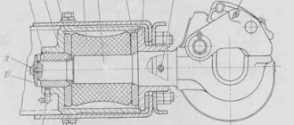
In the lower part, the balancers have a developed head, in the bore of which axle 2 (Fig. 78) of the rollers is installed on tapered roller bearings. It is held inside the balancers from axial displacement by tapered bearings, the lower rings of which rest against collars stamped in the middle part of the axle. The outer rings of the bearings are pressed by 6 seal housings, screwed with four bolts to the balancers. Steel track rollers / are pressed onto the protruding ends of the axle until they stop in the lower bearing rings, secured to the axle with a nut 14 and a feather key 13. The track rollers, cast from high-carbon steel, have thickened rims, hardened with high-frequency currents for greater wear resistance. A correctly installed axle with rollers attached to it rotates freely in the bearings and has a certain axial play, which is controlled by 20 gaskets installed between the flanges of the seal housings and the end walls of the balancer head. When the number of adjusting shims is reduced, the housing 6, with its centering shoulder, moves the outer ring of the bearing inside the balancer, thereby reducing the clearances in the bearings and, accordingly, the axial play of the roller axle. It should be borne in mind that it is necessary to reduce or increase the number of shims simultaneously and evenly on both sides of the balancer head. The tapered roller bearings of the roller axle operate in liquid lubricant, which is poured into the internal cavity of the balancer head. The leakage of lubricant and the ingress of foreign impurities into it are prevented by a seal on the hub of the support roller, arranged as follows. A metal round ring 5 is inserted into the housing 6, in the groove of which a rubber ring 18 is placed, ensuring the tightness and immobility of the connection of the ring with the housing. Pressed against ring 5 by spring 9, enclosed in a cover 10 made of oil-resistant rubber, is a small metal seal ring 7, loosely placed on the hub of the road wheel. Thanks to two flats on the roller hub, a small ring with a profile hole and a rubber boot with a spring rotate with the roller. Metal pressure washers I are inserted into the rubber boot to ensure a complete fit to the small o-ring and the end of the roller hub, as well as to protect the boot from breaking through the ends of the spring.
For ease of assembly and eliminating the wrapping of the ends of the rubber boot, it is assembled with the seal spring and washers separately before installation in the roller. The seal spring is pre-compressed to a height of 27.5 mm and tied in two places with threads.
Oil leakage between the flange of the seal housing 6 and the end surface of the balancer head, as well as from under the nut 14 of the roller axle, is prevented by rubber rings 19 and 16. Tightness at the point of contact between the stationary ring 5 and the small o-ring 7 rotating with the roller is created by the tight fit of precisely machined surfaces of these parts. During operation of the tractor, the surfaces of the rings are additionally ground in, resulting in improved tightness of the connections. To ensure high wear resistance, sealing rings are made of high-quality alloy steel and hardened. When assembling and installing the support rollers, you must carefully ensure that the surfaces of the rings are clean and covered with a thin layer of lubricant, since even small particles 1 - support roller; 2 — roller axis; 3 - balancer; 4 — tapered roller bearings; 5 - round seal ring; 6 — seal housing; 7 - small seal ring; 8 - double-walled cap; 9 — seal spring; 10 — rubber cover; 11 — pressure washer; 12 — bend washer; 13 - key; 14 — roller axle nut; 5 - conical plug; 16, 18 and 19 - rubber sealing rings; 17 — retaining ring; 20 — adjusting shims; 21 - the tip of the dust blower contributes to a loose fit of the rings and the appearance of burrs on them, causing oil leakage. Each ring only grinds on one side, so when installing it is necessary to ensure that they are pressed against each other only by these surfaces. Surfaces can be distinguished by acid marks, which are placed on the unpolished side. The round sealing ring is placed with the stamped surface against the thrust collar of the seal housing. The small ring with its branded side is pressed against the rubber cover.
For ease of installation of the track roller with the ring 7 assembled on it, a rubber boot with a spring and pressure washers, a spring lock ring 17 is installed in the groove at the end of the track roller hub. When the roller is removed, the sealing ring 7 rests against the lock ring under the action of a spring, thereby protecting the parts seals from falling off the hub.
To protect against direct ingress of dirt, the sealing unit is additionally closed with a labyrinth. This labyrinth is formed by a double-walled stamped cap 8, welded to the roller hub and a cylindrical shank of the housing 6 inserted between the walls of the cap.
Oil for lubricating the roller axle bearings is poured through its central hole, closed with plug 15.
Two radial holes in the axle and holes located opposite them in the hubs of the road wheels connect the central channel through tapered bearing cages with the internal cavity of the balancer head.
Oil is supplied by a supercharger, the tip of which is inserted into the central channel until it stops at the ledge located behind the first radial hole. Under pressure, oil flows through the central channel to the second radial hole and through it into the internal cavity of the balancer head. The displaced air and old lubricant exit through the first radial hole and the gap between the supercharger tip and the inner walls of the central channel.
The parts of tapered roller bearings take up a large load, so incorrect or untimely adjustment of them, as well as insufficient quantity of lubricant or poor quality of it, can reduce the performance and durability of the unit.