Device
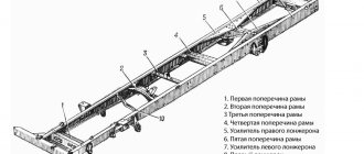
The Ural vehicle has a riveted frame, which is assembled from a pair of stamped spars of variable cross-section.
The elements are connected to each other by a front buffer and six cross members. The first to fourth cross members have a tubular cross-section, the fifth and sixth cross-members on the Ural-4320-01 machine are stamped, the sections are channel and I-beam. On the Ural-43202-01 and Ural-5557 vehicles, the role of the sixth cross member is played by the towing cross member.
The sixth cross member and the front buffer are designed to be removable. The vehicle is equipped with a pair of tow hooks at the front of the frame for towing vehicles. The Ural-4320-01 version has a pair of removable rear buffers at the rear of the frame. Where the balancer suspensions, rear front spring brackets and rear brackets of the main fuel tank are fixed, spar reinforcements are provided.
The frame of the Ural-44202-01 truck tractor is made similar to the frame of the Ural-4320-01 model, but its overhang length is reduced by 335 mm. Between the fifth and fourth crossbars there are riveted brackets for fixing the subframe of the saddle device.
The frame is provided with platforms that provide ease of manipulation with the fifth wheel device, and they also protect the fifth wheel device and the bottom of the semi-trailer from contamination. The rear ends of the side members are equipped with two rigid hooks instead of a towing device.
The Ural-5557 automobile frame has been extended by 290 mm. In the area between the fourth and second cross members, an internal amplifier is provided in the spar. The frame is equipped with brackets for fixing the subframe of the dump truck installation.
Principle of operation
The supporting part of the ends of the springs are brackets secured with a press on the bridges. The balancers rotate freely on the outer parts of the suspension axis and are fixed with spring stepladders. They rotate only in the direction of the axis without changing shape. Thanks to the listed characteristics, the car quickly adapts to imperfections in the road surface. When braking, the force passes to the frame through reaction rods and is transmitted to the springs. They restrict the movement of the bridge. Reaction rods are equipped with conical shortened fingers. The keys of the segments are protected by brackets from scrolling.
Towing device
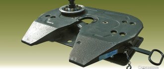
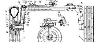
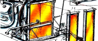
Fixed in a specially designed cross member. The towing hook rod 5 is inserted into the cylindrical body 2, which has a guide bushing 6, two pressure rings 3, a rubber elastic element 4 (Fig.).
Rice. Towing device: 1-nut; 2-body; 3-rings; 4-element elastic; 5-tow hook; 6-guide bushing; 7,9-masleiki; 8-cotter pin; 10-plate locking; 11-bolt
The locking pin 8 is installed when working with a trailer.
The crossbar with which the towing device model Ural-4320-01 is equipped differs from the crossbar of the Ural-5557 and Ural-43202-01 versions in terms of placement, design and mounting on the machine frame. On the Ural-4320-01 vehicle, below the frame side members, a cross member with a towing device is installed, secured with bolts to the lower flange of the side members and the sixth cross member. On models Ural-5557 and Ural-43202-01, the cross-member with the towing device is mounted between the frame side members and bolted to the vertical and lower flanges of the side members.
Spare parts for Ural, Kraz, MAZ, Kamaz trucks. Engine parts YaMZ-236, YaMZ-238
__________________________________________________________________________
__________________________________________________________________________
Suspension of cars Ural-4320, Ural-5557 and its parts
___________________________________________________________________________
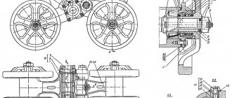
Front suspension Ural-4320, Ural-5557 The front suspension Ural-4320, 5557 (Fig. 31) consists of two longitudinal semi-elliptical springs working in conjunction with double-acting telescopic hydraulic shock absorbers.
Rice. 31. Front suspension of the Ural-4320, 5557 1.8-brackets (front, rear); 2-spring buffers; 3-bracket thrust buffer; 4-shock absorber; 5.17-shock absorber brackets; 6-bracket for additional buffer; 7-lining; 9-liners; 10-spring; 11-bolt lower fastening of the tie; 12-spacer sleeve; 13-clip additional buffer; 14-bolt upper fastening of the tie; 15-plate locking; 16- tie rod for rear brackets; 18-ladder springs; 19-finger spring eye; 20 - overlay; 21-ladder eye; 22 spring eye; 23-wedge; 24-bolt The upper lugs of the shock absorbers of the Ural-4320, 5557 suspension are attached to the bracket brackets 5 through rubber bushings, the lower lugs are attached to the brackets 17, welded to the axle housing. In the middle part of the springs, stepladders are attached to the axle housing. The upward movement of the Ural-4320, 5557 bridge is limited by rubber buffers 2, fixed in the linings 20 of springs and the clips of 13 additional buffers. Clip 13 is connected to bracket 6 attached to the frame spar. Additional buffers, in addition, reduce the tension in the springs during heavy braking, limiting the twist of the springs. At the front ends of the springs, lugs 22 are attached with stepladders 21 and bolts 24. The Ural-4320, 5557 springs are connected through the lugs to the front brackets 1 with pins 19, which are fixed in the brackets with wedges 23. The rear ends of the springs fit freely into the eyes of the rear brackets 8. Travel of the Ural bridge -4320, 5557 downward is limited by hooking the bend of the end of the third leaf of the spring to the lower bolt 11 of the tie rod fastening of the rear spring bracket, on which the spacer sleeve 12 is installed. To reduce the stress in the frame side members in the area of the second cross member, the rear spring brackets are connected by tie rod 16, which is attached to the brackets using bolts. The bolts are locked with plates 15. The front suspension of the Ural-4320, 5557 cars with the YaMZ-238M2 engine is distinguished by a reinforced spring. The spring uses the third and fourth sheets with a thickness of 12 mm, the remaining sheets with a thickness of 10 mm do not differ from the spring sheets of cars with a YaMZ-236M2 engine. Hydraulic shock absorbers Ural-4320, 5557 (Fig. 32) are designed to dampen vibrations resulting from elastic deformations of the vehicle’s suspension elements when driving on an uneven road. Rice. 32. Shock absorber for car suspension Ural-4320, 5557 1-upper head; 2-body nut; 3-washer; 4 rod seal; 5-body bushing; 6-washer; 7-ring seal; 8- oil seal housing; 9-shock absorber housing; 10-cylinder; 11- piston rod; 12-plates restrictive; 13,15,18-valve discs; 14 piston; 16- piston nut; 17-valve body; 19-disc throttle compression; 20-disc pressure; 21- spring; 22-cover The principle of operation of hydraulic shock absorbers Ural-4320, 5557 is as follows. With relative movements of the sprung and unsprung parts of the car, the liquid in the shock absorber, flowing from one cavity to another through small holes, resists the vertical movement of the rod and dampens the vibrations of the car. Suspension of the middle and rear axles Ural-4320, Ural-5557
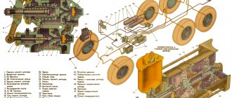
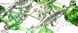
Rice. 33. Suspension of the middle and rear axles Ural-4320, 5557 1-spring; 2-stepladder; 3-spring pad; 4-nut stepladder; 5-spherical washer; 6-frame; 7.9-reaction rods (upper and lower); 8-support spring bracket; 10-buffer bracket; 11-buffer lining; 12-buffer; 13-cuff body; 14-cuff; 15-ring felt sealing; 16- spacer ring; 17-bolt securing the balancer axis; 18-bolt coupling; 19-bolts securing the balancer bracket to the fifth cross member; 20- balancer bracket; 21-axis balancer suspension; 22-axle bracket; 23-ring sealing; 24-pin ball; 25-balancer; 26-nut; 27-balancer cap; 28-filler plug Rear suspension Ural-4320, 5557 is of balancer type, the ends of the springs fit into the eyes of the support brackets 8 (Fig. 33). The Ural-4320 springs are attached by stepladders 2 to balancers 25, swinging on the axis 21 of the balancer. Brackets 22 are pressed onto the axle, through which the axle 21 is secured with bolts 17 to the balancer brackets 20. Pushing and braking forces are transmitted from the axles to the frame through two upper 7 and four lower 9 reaction rods. Lateral forces are transmitted through springs. The joints of the reaction rods Ural-4320, 5557 are ball joints. On the upper reaction rods on the side of the bridges there are pins with a shortened cone, which are kept from turning in the brackets by segment keys. The head of the Ural-4320, 5557 reaction rod is sealed on one side by a gasket installed under the cover, on the other side by an o-ring 23. The impact of the axles on the frame, received when a car wheel hits an obstacle, is softened by a buffer 12. The downward travel of the axles is limited by pinching the end of the spring in support bracket 8. The suspension of Ural-4320, 5557 vehicles with a rear bogie weight of over 12,000 kg is distinguished by the installation of reinforced springs (with sheets of greater thickness) and correspondingly elongated stepladders. Maintenance of suspension Ural-4320, 5557 To prevent shearing of the center bolt of the front spring and the centering extrusion of the rear spring, promptly tighten the nuts of the spring ladders on a loaded vehicle. If you hear a squeak in the springs, lift the car by the frame and inject lubricant into the gaps between the sheets. Whenever disassembling the Ural-4320, 5557 springs, lubricate the sheets, first removing old grease, dirt and traces of corrosion. Wash and lubricate the ears and pins of the front springs. Tighten the spring ladder nuts in accordance with Fig. 34: - front springs: first with a torque of 200-250 Nm (20-25 kg/cm), then finally with a torque of 400-500 Nm (40-50 kg/cm); — rear springs: first with a torque of 250-300 Nm (25-30 kg/cm), then finally with a torque of 580-660 Nm (58-66 kg/cm). Rice. 34. Scheme for tightening the nuts of stepladder springs Ural-4320, 5557 1-spring; 2-rear spring pad (front axle beam clamp); I-IV order of tightening the stepladder nuts When assembling, lubricate the threads of the stepladders with graphite lubricant. Tighten the stepladder nuts 21 (see Fig. 31) securing the front spring Ural-4320 on a loaded vehicle in the following order: Screw the nut until it stops; Unscrew the nut 1.5-2 turns; Unthread the threads at two opposite points on each rod. Full tightening of the stepladder nut is unacceptable, because this prevents the movement of sheets and will lead to rapid destruction of the stepladder and the eye fastening during operation. If there is no gap (less than 0.2 mm) between the front part of the eye and the top leaf of the Ural-4320 spring, repair or replace the eye. If the spring is removed from the car, tighten the stepladder nuts 21 to a torque of 20-28 Nm (2.0-2.8 kg/cm) and spread them out at two opposite points. Make sure that bolt 24 fastening the overhead lug is tightened. Tighten the nuts to a torque of 280 Nm (28 kg/cm). If the hole for the cotter pin in the bolt does not match the slots in the nut, tighten the nut and tighten it. When loosening the tie rod of the rear brackets of the front springs Ural-4320, 5557, tighten the bolts of its fastening. The tightening torque of the upper bolt 14 is 120-160 Nm (12-16 kg/cm), the nut of the lower bolt is 180-220 Nm (18-22 kg/cm). Lock the bolts by bending the locking plate onto the heads. If the ends of the first leaf of the rear spring Ural-4320, 5557 are worn to half the thickness, swap the first and second leaves. On the springs of Ural-4320, 5557 vehicles with a weight on the rear bogie of over 12,000 kg, it is not recommended to swap sheets. To remove stepladders 2 (see Fig. 33) without disconnecting the reaction rods, jack up the car and place a stand under the balancer axle or frame. Unscrew the stepladder nuts and remove the spring pad. Lower the car onto the stand so that there is a gap between the spring and the balancer. Turn the balancer at a slight angle and remove the stepladder. To eliminate axial movement of the balancer, unload the balancers by hanging the car frame so that the ends of the springs are not pinched in the support brackets. Remove the balancer cap 27. Loosen the coupling bolt 18, unscrew the nut 26, wipe the threaded parts of the nut and the balancer axis dry, and lubricate them with sealant. Screw nut 26 until it stops, and then unscrew it 1/6-1/4 turn. Squeezing sealant into the gap between the ends of the balancer nut and the bushing is not allowed. After adjustment, tighten the tightening bolt 18 to a torque of 44-56 Nm (4.4-5.6 kg/cm). Replace the damaged cap gasket by first lubricating it on both sides with sealant. Fill the balancer hubs with lubricant to the level of the filler hole in the cap. Do not allow the lubricant level to fall below the mark on the balancer caps. Due to the fact that the oil poured into the balancer hubs during assembly gradually fills the gaps in the joints and is absorbed into the wooden plugs pressed into the axle tube on both sides, a slight decrease in the oil level is possible. When preparing the Ural-4320, 5557 vehicle for operation, check the lubricant level in the balancer hubs and, if necessary, bring it to the level of the filler hole in the caps. Tighten the reaction rod pin nuts to a torque of 600 Nm (60 kg/cm). If the hole in the pin does not line up with the slots on the nut, tighten the nut until it matches and use a cotter pin. Fill the joints of the reaction rods with lubricant until fresh grease is squeezed out or until the rubber sealing rings begin to deform; however, squeezing out the grease is not necessary. Loosening of bolted connections of suspension parts is not allowed. If a leak of working fluid appears from the shock absorber, tighten nut 2 (see Fig. 32). When stretching and compressing, the Ural-4320, 5557 shock absorber must provide uniform resistance. The force during the rebound stroke should be in the range of 5.9-8.0 kN (595-805 kgf), and during the compression stroke - 1.5-2.2 kN (152-228 kgf); the force is checked on a press with a rod stroke of 100 mm and a frequency of 100 vibrations per minute. Free movement of the shock absorber rod Ural-4320, 5557 indicates its malfunction. Protect the polished surfaces of the rod, working cylinder and other parts from nicks and other damage. Procedure for replacing the working fluid: Secure the Ural-4320, 5557 shock absorber to the lower head in a vice and pull the rod out completely. Insert a special wrench into the gap formed between the casing and the housing and unscrew the housing nut. By gently shaking the upper end of the rod, remove it along with the piston from the working cylinder. Remove the working cylinder from the reservoir and completely drain the working fluid. During each disassembly, as well as when replacing fluid, wash all shock absorber parts in kerosene and dry. Lubricate the inner surface of the cuffs with shock-absorbing fluid. Fill the cylinder with liquid in accordance with the lubricants and working fluids chart. If there is not enough fluid, the shock absorber does not develop force, and if there is too much, it may fail. The use of other liquids as shock absorbers is unacceptable. Insert the piston and rod assembly into the cylinder, install the oil seal housing, sealing ring, washer, move the remaining parts and tighten the housing nut with a torque of 120-150 Nm (12-15 kg/cm). On the Ural-4320, 5557 shock absorber with a plastic casing, when stretched, access to the housing nut is blocked. To tighten the housing nut, remove the shock absorber from the car and, using the end of the casing, press it towards the upper head. After tightening the housing nut, install the casing in place.
_________________________________________________________________________
_________________________________________________________________________
_________________________________________________________________________
- Cardan shafts and power take-off Ural-4320
- Transmission gearbox Ural-4320
- Bridges Ural-4320
- Transfer case Ural-4320
- Steering Ural-4320
- Truck cranes and cranes based on trucks
_________________________________________________________________________
_________________________________________________________________________
- Cylinder block and cylinder head YaMZ-236 HE2, YaMZ-236 BE2
- Checking and adjusting YaMZ-236
- Power system and lubrication system YaMZ-236
- Driven and driven clutch discs YaMZ-236, 238
- Cooling and lubrication systems YaMZ-238
- Fuel injection pump YaMZ-238
_________________________________________________________________________
- Kamaz diesel engine
- Repair and adjustment of Kamaz power steering
- Kamaz-152 gearbox with divider
- Gearbox parts for Kamaz-5320 gearbox
- Kamaz transfer case and driveshafts
- Kamaz gearbox repair
- Clutch KamAZ-5320
- Construction of Kamaz-4310 drive axles
- Power steering MAZ-5551, 5549, 5335, 5336, 5337
- Front axle and steering rods MAZ-5551, 5549, 5335, 5336, 5337
- Clutch adjustment MAZ-5551, 5549, 5335, 5336, 5337
- Adjustment and repair of gearboxes MAZ-5551, 5549, 5335, 5336, 5337
- Repair and maintenance of the rear axle MAZ-5551, 5549, 5335, 5336, 5337
- Front axle parts and steering rods MAZ-5516, 5440
- Steering Maz-5516, 5440
- Details of driving axles Maz-5516, 5440
- Clutch device ZIL-130
- Repair of ZIL-130 gearbox
- Repair of rear axle ZIL-130
- Basic parts of the ZIL-130 engine
- Transfer case and power take-off ZIL-131
- Drive axles ZIL-131
- Steering ZIL-131
- Maintenance of ZIL-645 engine parts
Traveling with a trailer
To ensure the functionality of the towing device, you need to use a tow hitch loop with a section size of 42 mm and an internal diameter of 90 mm, a towing device hook with a width in the throat area of 69 mm and a throat diameter of 48 mm. The maximum dimensions that are allowed are: hook opening 52 mm, loop section 38 mm, hook width 66 mm.
Towing hooks and coupling eyes, the dimensions of which do not match the above, should be replaced with new ones.
During maneuvering, it is not recommended to allow the trailer to be folded all the way to the end of the side member of the towbar frame.
If these requirements are not met, the towing loop may become jammed in the towing hook, and parts of the towing device may be damaged.
Maintenance
During use, it is recommended to periodically monitor the condition of the side members, brackets, cross members, as well as rivet and bolt connections.
The towing device is cleaned of dirt and lubricated during maintenance. The guides of the towing hook rod are lubricated using an oiler during maintenance of the machine.
The hook should rotate freely, by hand, in the sleeve 6 and the housing support 2. The movement of the hook along the axis in the housing should not exceed the 0.5 mm bar. If this parameter is greater, then to correct it you need to tighten the nut until a gap appears between pressure ring 3 and body 2 due to deformation of the elastic element. Next, the nut is unscrewed until axial displacement of the hook is eliminated and fixed with a locking plate with a bolt. The plate, together with the bolt screwed into the plate hole, and the towing hook rod can be rotated to the distance of the gaps in the connection.
Checking the elements of the rear suspension "Ural"
Springs are checked before installation. Without a load, the spring should produce the following parameters: deflection of 98 mm with an error of 10 mm, with a load of 4480 kgf - 13 mm. If the specified characteristics do not comply, the spring is unsuitable for use.
The surface of the sheets must be smooth, without deformation or cracks. If the spring leaves are worn down to more than half of the base width, the spring is replaced. When changing thrust bushings, it is better to leave play up to 0.30 mm. The normal distance between the hinge elements is 2-3 mm. To obtain the required gap size, the ends are ground.
Installation of the Ural rear suspension elements is carried out in reverse order and in accordance with the car model. Before installation work, each sheet is treated with graphite lubricant. The balancer axis is impregnated with technical mineral oil heated to 60 degrees. The nuts are tightened until they stop, and then loosened until the balancer begins to rotate freely by hand. The final part of the assembly is securing the pinch bolt.