It is necessary to ensure that there are no leaks of coolant and fuel in the connections of pipelines, hoses and taps, systematically inspect the pre-heater and immediately correct any detected faults. The connections between the fuel lines and the heater must be sealed, since air leaks into the fuel system are not allowed. The presence of air or a leak in the fuel system of the heater leads to unreliable operation and random stoppage of the heater.
It is necessary to regularly inspect the fastenings of the boiler and pump unit, clean all equipment from dirt, wash the filters of the solenoid valve and nozzles, clean the drain holes of the fuel pump and the drain pipe of the boiler burner from dirt. In addition, it is also necessary to clean the spark plug electrodes from carbon deposits, disassemble and wash the injector in gasoline or acetone, wash the solenoid valve channels in kerosene or gasoline, clean the valve core from dirt, check the condition of the wires and the fastening of the heater control devices.
Design and operating principle of 14TS-10
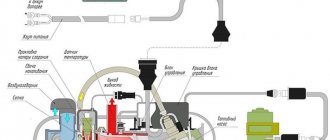
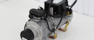
The 14TS 10 device is a special device built into a break in the circuit of the engine liquid cooling system. Structurally, it consists of a housing in which a combustion chamber, a built-in heat exchanger and an electric pump are located. Switching on and monitoring the operation of the heater is carried out by a control unit with a remote control. The heater is connected to the fuel system and on-board electrical network of the vehicle.
When fuel burns in the heater chamber, heat is released, which is transferred to the heat exchanger. The liquid passing through it is heated and, with the help of a built-in pump, circulates in the engine water cooling system.
The camera operation process is controlled by a combustion indicator. Having reached the specified heating temperature limit (80°C), combustion stops and the device begins to cool down. The heated liquid continues to circulate in the system.
Automatic operation of the 14TC-10 is carried out according to one of the selected programs: economical or pre-start. In the first case, the operating cycle lasts 8 hours at low power, in the second, heating occurs in 3 hours at maximum power.
content .. 21 22 25 ..Pre-heating system PZD-600 for engine D12A-375B
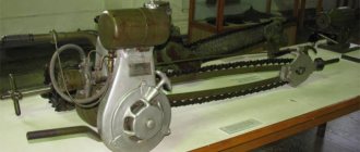
To ensure engine starting at low temperatures, a starting heater PZD-600 is installed on cars.
(see Fig. 37). The heater runs on diesel fuel and is connected to the engine power supply system (see Fig. 20).
The heat released during the combustion of fuel in the heater boiler 16 (see Fig. 37) is taken up by the coolant, which is driven by a special circulation pump of the heater first through the oil heating coils 14 in the engine oil tank, and then through the engine cooling jacket and further in a small circle circulation returns to the heater again.
Rice. 42. Tension roller: 1 - double-arm lever; 2 — axis of the double-arm lever; 3 - tension roller; 4 — grease fitting; 5 - cover; 6 - bearings; 7 — felt seal; 8 - roller axis
Device of the PZD-600 heater for the D12A-375B engine
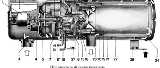
The heater (Fig. 43) consists of a cylindrical boiler and auxiliary components mounted on it: burner, pump unit, nozzle, solenoid valve, glow plug. A heater control panel is installed in the driver's cab.
The heater boiler is made of stainless steel and consists of four cylinders forming a combustion chamber 7, a gas pipeline 10 and a jacket 8 for the heated liquid.
The liquid enters the boiler through pipeline 11 under pressure from circulation pump 4, passes through the entire boiler jacket and is discharged from the boiler through pipeline 6.
Rice. 43. Heater:
1 - gear type l and other pump; 2 - electric motor; 3 - fan; A - circulation pump; 5 — inlet pipeline of the circulation pump; 6 - hot liquid outlet pipeline; 7 - combustion chamber; 8 - outer jacket; 9 - inner jacket; 10 - gas pipeline; 11 — pipeline for supplying liquid to the boiler; 12 — drain tap; 13 — exhaust pipeline; 14 — outer cylinder of the combustion chamber; 15 — glow plug; 16 — swirler; 17 — nozzle; 18 - solenoid valve; 19 — fuel pipe; 20 - internal cylinder of the combustion chamber
The heater burner consists of an outer cylinder 14 and an inner cylinder 20. A primary air swirler 16 is installed between the burner cover and the inner cylinder.
Secondary air is supplied to the combustion chamber through holes in the inner cylinder.
The heater pump unit is driven by an electric motor 2 and consists of a fan 3, a circulation pump 4 and a gear fuel pump 1.
The heater nozzle (Fig. 44) is of a centrifugal type, with a stacked plate filter. In case of clogging, the nozzle must be removed, disassembled, cleaned and checked in a spray bath, turning on the heater and without inserting the nozzle into the burner. The injector must produce a mist-like cone of fuel with a spray angle of at least 60°.
The solenoid valve stops supplying fuel to the injector when the heater is turned off.
When the heater is started, the fuel-air mixture is ignited by the glow plug. Then the candle turns off and combustion is maintained automatically. Fuel is supplied by a pump through an open solenoid valve to the nozzle and from the nozzle under a pressure of 6-7 kg/cm2 enters the combustion chamber.
When operating the heater, the following requirements must be observed.
Fill the cooling system with non-freezing liquid (antifreeze). In exceptional cases, at an ambient temperature not lower than -30° C, it is allowed to fill the cooling system with hot water.
It is prohibited to start the heater without coolant in the boiler, as well as to refuel an overheated boiler to avoid damage to it.
It is prohibited to start the heater immediately after stopping or restart it if the first start attempt is unsuccessful without first purging the combustion chamber for 3-5 minutes.
When the heater is operating, the driver should not leave the vehicle in order, if necessary, to promptly eliminate any malfunction or eliminate the source of the fire. Simultaneous operation of the engine and heater must not be allowed to avoid damage to the heater.
Rice. 44. Nozzle: 1 - body; 2 - camera; 3 - gasket; 4 - screw; 5 — cover rod; 6 - end plate; 7 - fitting; 8 — filter plate; 9 - filter cover
The heater is started in the following sequence:
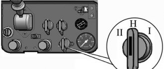
Set switch 2 of the solenoid valve on the control panel (see Fig. 7) to the Blowing position and turn on
10-15 sec electric motor with switch 3, setting it to the Work-position,
turn on the glow plug for 30-40 seconds by moving switch lever 5 to the left. At the same time, the control spiral / on the panel should glow to a bright red color;
move switch 2 of the solenoid valve from the Blowing position to the Operation position and switch 3 of the electric motor operating modes to the Start position, if the ambient temperature is below -20 ° C.
At higher temperatures, you can move switch 3 directly to the Run position, bypassing the Start position.
If you hear the hum of a flame in the heater boiler, release spark plug switch 5 and move switch 3 to the Operation position (at temperatures below -20° C).
If there is no characteristic flame hum in the heater boiler, move switch 3 to the neutral position, switch 2 of the solenoid valve to the Blowing position and repeat the start-up process.
If the heater fails to start within a few minutes, check the fuel supply to the combustion chamber and the glow of the spark plug.
Starting the heater is considered normal if, with a uniform hum of the flame in the boiler, after 3-5 minutes the pipeline draining liquid from the heater is hot and the outer casing of the boiler is cold.
Strong heating of the outer casing of the boiler and the appearance of shocks of boiling liquid in the boiler indicate a lack of liquid circulation. In this case, it is necessary to turn off the heater and find out the cause of the malfunction.
The operation of the heater is accompanied by a uniform hum of the flame in the boiler and the release of exhaust gases from the heater with a bluish glow. Periodic projection of flames up to 100 mm long is allowed.
After heating the coolant in the engine to a temperature of + 40 ° C, periodically, but not more than for 20 seconds, turn on the engine oil pump to mix and uniformly heat the oil.
The fuel supply to the heater is regulated by the screw of the fuel pump pressure reducing valve (as the gears wear) on the operating heater.
Turn off the heater to stop operation in the following sequence:
set switch 2 of the solenoid valve to the Purge position to stop the supply of fuel to the combustion chamber;
Let the electric motor run for 1-2 minutes to purge the combustion chamber, then turn it off by moving switch 3 to the neutral position.
The combustion chamber and gas pipeline are purged to eliminate a possible gas explosion during the subsequent start-up of the heater.
Rice. 45. Electrical circuit of the heater: 1 - fuse PR2B; 2 - protection block B320 with fuse link 2a; 3 - switch; 4 - switch; 5 — control spiral; 6 — connecting panel; 7 — glow plug; c - solenoid valve; 9 — supercharger; 10 - electric motor; 11 - resistance panel; 12 — switch PPN-45 of the electric motor
content .. 21 22 25 ..
Basic operating modes of 14TS-10
Using the regulator on the remote control, you can select one of three possible operating modes of the device, regulated by the control unit:
If the temperature drops to 55°C, the device automatically switches to the “Full” mode during the pre-start or “Medium” mode during the economical program.
The unit carries out preliminary and current diagnostics of 14TS-10, as well as control of specified operating modes. Using the remote control, the device is turned on, operating modes are selected and its parameters are controlled.
Error codes from the Teplostar timer remote control
| Code | Malfunction | Trouble-shooting |
| 01 | Overheat. |
|
| 02 | Possible overheating detected. The temperature difference between the overheating sensor and the temperature sensor is too large. |
|
| 03 | Overheating sensor malfunction. | Check connecting wires. The output signal and voltage are linearly dependent on temperature (0°C corresponds to 2.73 V and with an increase in temperature by 1°C, the output signal increases by 10 mV, respectively). Check the overheating sensor and replace if necessary. |
| 04 | Temperature sensor malfunction. | Check connecting wires. The output signal and voltage are linearly dependent on temperature (0°C corresponds to 2.73 V and with an increase in temperature by 1°C, the output signal increases by 10 mV, respectively). Check the temperature sensor and replace if necessary. |
| 05 | Flame indicator broken. | Check connecting wires. Check the ohmic resistance between the flame indicator terminals. If there is a break, the ohmic resistance is more than 90 ohms. If broken, replace the flame indicator. |
| 06 | Flame indicator short circuit. | Check connecting wires. Check the ohmic resistance between the flame indicator terminals. During a short circuit, the ohmic resistance is less than 10 ohms. If there is a short circuit, replace the flame indicator. |
| 07 | Flame interruption in “SMALL” operating mode. | Check the air intake, gas exhaust pipe and fuel supply, eliminate faults, replace the fuel pump and flame indicator if necessary. |
| 08 | Flame interruption in “FULL” operating mode. | Check the air intake, gas exhaust pipe and fuel supply, eliminate faults, replace the fuel pump and flame indicator if necessary. |
| 09 | Faulty glow plug. | Check the glow plug and replace the glow plug if necessary. |
| 10 | Air blower motor malfunction. | Check the electrical wiring of the electric motor. Eliminate the malfunction and, if necessary, replace the air blower. |
| 12 | Shutdown, increased voltage more than 30.8 V. | This defect is possible when the heater is turned on while the car engine is running. The cause may be a faulty vehicle voltage regulator. |
| 13 | Startup attempts exhausted. | If the permissible number of starting attempts has been used, check the quantity and supply of fuel. Check the air intake and exhaust pipe. Check the spark plug. |
| 14 | Malfunction of the circulation pump (pump). | Check the electrical wires of the circulation pump for short circuits and breaks, check the pump and replace if necessary. |
| 15 | Shutdown, undervoltage less than 20 V. | Check the battery, vehicle voltage regulator and supply wiring. |
| 16 | Ventilation time exceeded. | The heater is not cooled sufficiently during purging. Check the air intake and exhaust pipe. Check the flame indicator and replace if necessary. |
| 17 | Fuel pump malfunction. | Check the fuel pump electrical wires for short circuits and breaks, check the fuel pump and replace if necessary. |
| 18 | Car fan relay malfunction. | Check the electrical wires of the relay, eliminate the short circuit, and replace the relay if necessary. |
| 19 | Flame interruption in “MEDIUM” mode. | Check the air intake, gas exhaust pipe and fuel supply, eliminate faults, replace the fuel pump and flame indicator if necessary. |
| 20 | There is no connection between the control unit and the timer. | Check the 5 A fuse. Check the circuits and contacts. |
| 23 | Voltage less than 21.6 V (Warning). | It is necessary to turn off the operating heater and charge the battery. |
| 25 | The heater is blocked from subsequent starts after three consecutive starts during which the heater did not start. | The blocking is removed by disconnecting the heater from the battery. Check the glow plug. Check the mesh and the hole in the combustion chamber for carbon formation. See also code 17. |
Error codes and methods for eliminating them
A characteristic feature of the 14TS-10 device is the ability for the operator to independently diagnose emerging problems by flashing the LED located on the control panel.
When the heater is started and functioning normally, the LED lights up constantly. When disabled, the LED does not light up. If the device does not turn on, you need to check the supply of fuel and power through the 5A and 25A fuses.
If any malfunction occurs during operation of the device, the LED begins to blink a certain number of times. By the number of flashes (from 1 to 10), the operator can determine the specific problem and how to solve it, guided by the following table:
Number of LED flashes
Signs of malfunctions
Possible causes and solutions
The heat exchanger has heated up above permissible limits
1) Temperature sensors and overheating indicator give readings of more than 102°C. It is necessary to check the circulation pump and the integrity of the cooling system.
2) The readings of the temperature sensor and the overheating alarm differ by more than 20°C. In this case, you need to check their serviceability and change if necessary. Check the functionality of the pump.
The number of attempts to turn on the device has expired
Check the fuel supply to the device. Additionally, it is recommended to inspect the air intake and exhaust gas exhaust pipelines of the combustion chamber.
Periodic flame extinction
1) Check the flow of fuel into the heater, as well as the operability of the air supply system of the combustion chamber.
2) If the device turns on, you should make sure that the light indicator is working properly and replace the faulty one.
3) The fuel filter may be clogged. It needs to be inspected, cleaned or replaced.
Glow plug failure or blower motor failure
1) Check the serviceability of the glow plug; if defects are detected, replace it.
2) Check the serviceability of the air blower and the integrity of its electrical wiring. If defects are detected, the engine must be replaced.
Malfunctions of the flame indicator
Inspect the integrity of the electrical wiring, use a tester to measure the resistance at the contacts in the connector block of the indicator. If this parameter exceeds 90 Ohms, a break has occurred, if less than 10 Ohms, a short circuit has occurred. In such cases, the indicator will need to be replaced.
The temperature sensor or overheating alarm is faulty
It is necessary to inspect the condition of the connecting electrical wires. Measure the voltage level at the output of the sensors, which is directly dependent on the temperature: 0°C corresponds to an output voltage value of 2.73V, an increase of each degree leads to an increase in the output voltage by 10mV. Faulty sensors should be replaced.
The circulation pump does not work
1) Check the electrical wires and connector of the circular pump, its condition and functionality. Replace the faulty unit.
2) Check the serviceability of the pump activation relay; if defects are detected, replace it.
3) Check the functioning of the fuel pump and its connecting electrical wires, and replace if defects are detected.
The connection between the control unit and the remote control is broken
Inspect the condition of the connectors and the integrity of the electrical wires connecting the control unit to the remote control. Correct connection problems.
Increased or decreased level of switching voltage
Check the condition of the battery, voltage regulator and electrical wires of the vehicle's on-board network. Measure the voltage at the input to the device, the level of which should show no lower than 20V and not exceed 30.8V.
Exceeding the time to turn on the ventilation operation
The device does not cool well within the set time. It is necessary to check that there is sufficient air supply into the chamber, as well as the serviceability of the combustion indicator. If defects are detected, replace it.
It is recommended to keep this table in the car to quickly identify the problem and solve it.
Operation of pre-heaters using the example of Webasto – With my own eyes
Installation and repair of PZD
Important! It is better to install the PZD at specialized stations in order to avoid failure of vehicle systems or devices. Before the start of each cold season, it is necessary to carry out a technical inspection of the equipment.
The PZD-30 pre-heater device is started in a certain order:
- Activation of the battery switch - start by pressing the PZD switch button.
- Opening the valve on the fuel tank and filling the system with fuel in a KamAZ truck.
- Set the knob to position III and activate the heating start, taking into account the outside temperature.
- Move the handle to the reverse position I until the fuel ignites (characteristic sound).
- Automatic switching to steady heating mode
When the PZD is turned on, there is a stable hum in the system. This means that fuel combustion occurs in the heat exchanger and exhaust gases exit through the exhaust system without the formation of smoke or an open flame.
If disturbances occur in the operation of the KamAZ pump, you should initially adjust the fuel consumption using the pressure reducing valve. When changing and turning the valve to the right, the fuel supply increases, and to the left, it decreases. Depending on the stated requirements, it is necessary to set the lever to the optimal position. It is recommended to debug the fuel supply system depending on temperature changes. This will ensure not only more stable operation of the heating system, but also significantly reduce refueling costs.
Important! If you wash your car or water gets into the air fan, you need to remove it by turning the pump unit to position III for up to 3 minutes.
Functionality check
- Check the presence of antifreeze fluid in the engine cooling system
- Diagnosis of tightness of connecting nodes
- Electric heater diagnostics
- Bleed the fuel system manually
- Put the KamAZ PZD into action for 15-20 seconds
- Diagnosis of fuel leakage and presence of open flame
The PZD-30 engine pre-heater is a necessary device not only for comfortable and quick starting of a car engine, but also for saving fuel when warming up the cabin and fuel system, increasing the service life and wear of parts, the availability of the device (manufactured in the Russian Federation), and an affordable price.
What is PZD
A pre-heater on KamAZ is necessary to warm up a cold engine equipped with a liquid cooling system. It also prevents glass from icing up.
Device
The device includes the following elements:
Technical characteristics of the engine pre-start fuse:
At idle - 0.7
Principle of operation
The PZD is connected to the liquid system of the heating and cooling device of the vehicle. The system must be filled with coolant.
The heating device itself does not depend on whether the engine is running or not.
The heating device is powered by the vehicle. When the diesel engine is turned on, fuel begins to flow from the plunger-type electromagnetic fuel pump through the glow plug bushing. The fuel liquid is combined with air, which is supplied by a special supercharger. The air flow passes through the pipe. The resulting mixture begins to ignite from the hot spiral of the glow plug, after which the glow plug turns off.
The combustion process is maintained due to the continuous supply of fuel-air mixture. Hot gases heat the walls of the heat exchange mechanism. Exhaust gases passing through the pipe are released into the atmosphere.
Security measures
- Putting the pre-heater into operation and starting the engine is only possible if there is a sufficient amount of coolant in the system. Violation of this requirement can lead to boiler burnout, cracks in the cylinder liners and cylinder head, etc.
- Avoid oiling areas near the exhaust pipe of the heater boiler to prevent fire.
- The joint operation of the heater and the engine is unacceptable, because The flow of coolant during their operation is in the opposite direction. To avoid failure of the cooling system components and engine heating, it is necessary to first stop the heater and only then start the engine.
- It is not allowed to leave the motor grader while the heater is operating. If flame or smoke appears in the exhaust gases, immediately turn off the heater.
Preheater PZD-30 for Kamaz vehicle
Technical characteristics of the engine pre-start fuse:
| Heating capacity, kW | 12+1 |
| Fuel fluid consumption, l | During operation - 1.6 At idle - 0.7 |
| Diesel fuel requirements | GOST 305-82 (50% diesel + 50% gasoline) |
| Voltage, V | Up to 30 |
| Electrical power consumption, W | 70+10 |
| Rated voltage, V | 24 |
| Minimum amount of liquid for heating, l | 10 |
| CO content of gases at the outlet | No more than 4 |
| Smokiness | No more than 0.2% |
| Maximum operating pressure, kPa | From 40 |
| Weight, kg | 9 |
| Resource, h | 3000 |
Principle of operation
The PZD is connected to the liquid system of the heating and cooling device of the vehicle. The system must be filled with coolant.
The heating device itself does not depend on whether the engine is running or not.
The heating device is powered by the vehicle. When the diesel engine is turned on, fuel begins to flow from the plunger-type electromagnetic fuel pump through the glow plug bushing. The fuel liquid is combined with air, which is supplied by a special supercharger. The air flow passes through the pipe. The resulting mixture begins to ignite from the hot spiral of the glow plug, after which the glow plug turns off.
The combustion process is maintained due to the continuous supply of fuel-air mixture. Hot gases heat the walls of the heat exchange mechanism. Exhaust gases passing through the pipe are released into the atmosphere.
BINAR 5S-Comfort with control panel PU 20
| Code | Malfunction | Recommendations for elimination |
| 01 | Overheat. Liquid temperature is above 120°C. |
|
| 03 | Temperature sensor No. 1 malfunction. | Replace sensor. |
| 04 | Temperature sensor No. 2 malfunction. | Replace sensor. |
| 05 | Flame indicator malfunction. | Check connecting wires. Check the ohmic resistance between the indicator contacts, which should be no more than 10 Ohms. If there is a malfunction, replace the flame indicator. |
| 06 | Malfunction of the temperature sensor on the control unit. | Replace the heater control unit. |
| 09 | Faulty glow plug. | Check the glow plug and replace if necessary. |
| 10 | Air blower malfunction. The revolutions are below par. | Check the electrical wiring of the electric motor. Eliminate the malfunction and, if necessary, replace the air blower. |
| 12 | Shutdown, increased voltage more than 16 V (30.8 V). | This defect is possible when the heater is turned on while the car engine is running. The cause may be a faulty vehicle voltage regulator. |
| 13 | Startup attempts exhausted. | If the permissible number of starting attempts has been used, check the quantity and supply of fuel. Check the air intake, filter and exhaust pipe. Check the spark plug. |
| 14 | Pump malfunction. | Check the electrical wires of the circulation pump for short circuits and breaks, check the pump and replace if necessary. |
| 15 | Shutdown, undervoltage less than 10V (20V). | Check the voltage at the heater connector XS2. Check the battery, vehicle voltage regulator and supply wiring. |
| 16 | Ventilation time exceeded. | During purging, the flame sensor is not cooled sufficiently. Check the air intake, filter and exhaust pipe. Check the flame indicator and replace if necessary. |
| 17 | Fuel pump malfunction. | Check the fuel pump electrical wires for short circuits and replace if necessary. |
| 20 | There is no connection between the control unit and the remote control. | Check connecting wires and connectors. The control panel does not receive data from the control unit. |
| 22 | Fuel pump malfunction. | Check the electrical wires of the fuel pump for breaks, replace if necessary. |
| 24 | A sharp change in temperature on one of the sensors. | Possible overheating in the area of one of the temperature sensors due to poor coolant circulation. |
| 25 | The coolant heats up too quickly. | Check the complete fluid circuit. During 1 operating cycle, the heater reached standby mode three times in less than 6 minutes. |
| 26 | Air blower overload. | Check the air blower. It is possible that the air blower impeller may rub against the heater body as a result of the mounting being misaligned. |
| 27 | Air blower malfunction. The motor does not rotate. | Check electrical wiring, air blower and control unit, replace if necessary. |
| 28 | Air blower malfunction. The motor rotates without control. | Check electrical wiring, air blower and control unit, replace if necessary. |
| 29 | Ignition attempts have been exhausted while the heater is operating. | Check the fuel system. Check the tightness of the clamps on the fuel line, the tightness of the fuel line, the tightness of the fitting on the fuel pump, the performance of the fuel pump. |
| 30 | There is no connection between the control unit and the remote control. | Check connecting wires and connectors. The control unit does not receive data from the control panel. |
| 37 | The heater is blocked. | To unlock the heater, contact the service center. |
| 50 | There is no connection between the control panel and the modem. | Check connecting wires and connectors. |
| 78 | A flame failure was recorded during operation. | Shown for user information. Check the tightness of the clamps on the fuel line, the tightness of the fuel line, the tightness of the fitting on the fuel pump. |
Heater device
The PZD includes the following elements:
In some cases, additional equipment is installed on vehicles.
The heater can occupy one of four positions. Zero is when the device is completely turned off. It does not function at all, is not connected and does not work.
The first position is characterized by connected equipment and operating heating. The fuel goes straight to the burner, where it combines with air. The resulting substance ignites.
The second position is characterized by sending a flammable substance to a special combustion compartment. This is the main operating mode of the equipment. The substance lights up using a special torch.
The third position is characterized by preparatory work of the heater. The boiler is purged with ordinary air while heating the fuel.
The standard characteristics of the PZD for KamAZ guarantee 3,000 hours of operation.
General signs of malfunction of Pramotronic flare heaters
| Symptoms of a problem | Possible reasons |
| The heater does not start. | There is no voltage supply, the connection polarity is reversed. |
| There is no ignition. | Lack of fuel. The fuel pump is not working. The solenoid does not open. The injector is clogged, the connection of the fuel lines is leaking (the pump sucks in air). There is no sparking. |
| The heater does not provide high-quality combustion. | Excess fuel, injector contamination. Incorrect fuel spray angle, less than 80º. |
| The heater smokes during operation. | Incomplete combustion of fuel. Low motor speed. |
PZD 15.8106 for KamAZ 65115
Using a specific model as an example, we will analyze the safety requirements during operation:
Features of the operation of the Teplostar 14TS-10 PZD:
How does automatic control work in case of emergency situations:
In the event of an emergency shutdown of the diesel pre-heater, the LED on the control panel will light up, the number of blinks of which indicates the fault code. The explanation of errors and how to eliminate them can be found in the operating instructions.
Basics of operation of KamAZ railways
The KamAZ liquid heater works in conjunction with the vehicle’s heating equipment. At the same time, for the heater to work properly, a cooler must be present. Otherwise, the PZD will not be able to function.
The device receives power directly from the truck. As soon as the heater is turned on, a certain amount of fuel is sent. First, the electromagnetic pump turns on, and then the spark plug comes into play. The air comes into contact with the fuel through the nozzle, after which the hot candle provokes a fire. As soon as this happens, the candle turns off.
Combustion is maintained by constant contact of air with the combustible substance. Vapors of the hot substance come into contact with the walls of the heat exchanger. Exhaust gases are safely discharged through the exhaust pipe outside the vehicle.
The PZD can work even when the engine is turned off. There is no dependence of these devices on each other.
PZD KamAZ - engine preheater, characteristics, analysis
During the cold season, car owners are forced to deal with the problem of freezing of the car and its fuel system. Endless temperature changes and dampness in winter can have a detrimental effect on the operation of the machine, rapid failure of parts and engine shutdown as a whole. To get rid of these problems, install an engine pre-heater or, in common parlance, a KamAZ PZD.
PZD-30 is installed on KamAZ vehicles and is a pre-starting liquid engine heater that is capable of operating unhindered at ambient temperatures from minus 45°C to plus 60°C. In this way, it is possible to simplify the task of owners in the fight against icing of glass, freezing of the cabin, and making it easier to start the fuel system of the car.
Important! Installing a PZD on KamAZ can not only reduce the wear of parts, but can also increase the service life of equipment and its units in severe frost.
Pre-heater adjustment
Normal operation of the preheater is characterized by a uniform hum when burning in the boiler and a bluish color of the exhaust gases.
Rice. 2.11 Gear fuel pump
1 - coupling; 2 - adapter; 3 - nut; 4 - oil seal; 5 — body; 6 - bolt; 7 — spacer; 8 - cover; 9 driven roller; 10 - plug; 11 — drive roller; 12 - seal; 13 - spring; 14 - lock nut; 15 - union nut; 16 — adjusting screw; 17 - fitting; 18-ball
Otherwise, adjustment of the heater is required, which is done by screw 16 (Fig. 2.11) of the pressure reducing valve of the gear fuel pump. To do this you need:
It is recommended to adjust the fuel supply at temperatures no higher than minus 5°C.
Timer-thermostat Pramotronic (15.8106, 151.8106, 141.8106)
| Code | Timer indication | Indication on the warning lamp | Malfunction |
| 1 | E-01 | 1 flash | Failure to start the heater. |
| 2 | E-02 | 2 flashes | No flame ignition. |
| 3 | E-03 | 3 flashes | The supply voltage is below normal. |
| 4 | E-04 | 4 flashes | Flame indicator circuit malfunction. |
| 5 | E-05 | 5 flashes | Malfunction of the high voltage power supply circuit. |
| 6 | E-06 | 6 flashes | Temperature sensor defective. |
| 7 | E-07 | 7 flashes | Solenoid valve circuit malfunction. |
| 8 | E-08 | 8 flashes | Heater fan motor circuit malfunction. |
| 9 | E-09 | 9 flashes | Electric pump circuit malfunction. |
| 10 | E-10 | 10 flashes | The supply voltage is higher than normal. |
| 11 | E-20 | Lack of communication between the control unit and the timer-thermostat. |
Errors and their elimination
When the Teplostar does not start or some part in it has failed, the first thing you need to do is inspect the connectors and contacts. Their characteristics are presented in the table:
Many faults are displayed as error codes.
Each of them has its own decoding. Thanks to such signals, you can fix the problem yourself. Error codes PZD 14TS-10 and their interpretation by the number of blinks from 1 to 10:
Opinions about Teplostar are mostly positive. If you want to purchase it, then you should read the reviews and make sure that it is really necessary. The model range consists of the 11TS heater and 16 modifications of the 14TS. The manufacturer provides a guarantee for each device, but if instructions for proper operation are ignored, claims regarding malfunctions will not be considered.
Error codes and possible malfunctions of PZD-14TS
Error codes are related to the blinking LED. By the number of blinks you can determine the error:
- Overheating of the heat exchanger or a large temperature difference, which is indicated by temperature and overheating sensors.
- Too many engine starts.
- Interruptions in fuel combustion in the PZD combustion chamber.
- The spark plug or air blower is faulty.
- The flame indicator is faulty.
- One of the temperature or overheating sensors is faulty.
- The fuel pump is faulty.
- There is no connection between the control unit and the control panel.
- There is a problem with the power supply.
- Ventilation time exceeded.
Design and device
The design of the KAMAZ pre-heater includes several main components:
- boiler room;
- burner;
- water pump;
- remote control device.
The main element is the boiler compartment, which consists of 4 durable cylinders that form a heat exchanger. This part includes 2 cavities that facilitate the unhindered passage of exhaust gas and coolant circulation. There are 3 tubes on the outer part of the engine heater, 2 of them are intended for draining or supplying antifreeze, one is for exhaust gas removal.
Pre-heater device
The exhaust gases hit the damped part of the boiler, which due to this action change direction and flow to the outlet pipe. In this case, thermal energy is consumed for heating in the engine sump.
On the reverse side, at the open end of the boiler compartment, a burner is mounted, which includes:
- spark plug;
- nozzle;
- valve;
- fuel heater;
- gas heater.
The pump is considered a separate unit that combines three main pumps - liquid, fuel, air. It is in this system that it differs from other types of pre-heaters.
For example, a modification of the PZD 30 heater has a pumping apparatus, which is designed as a separate unit. Such a device is installed both above the boiler room and in any most convenient place. In this case, the device is connected with hoses of different diameters and lengths.
Important Technical characteristics and configuration options for the MAZ-103 bus
Pumping unit design
Devices 15-8106 and other similar analogues are mounted on the edge of the boiler, near the burner. This installation option makes it possible to eliminate the need to use long hoses, which leads to a significant reduction in the dimensional parameters of the entire preheater.
Boiler heater design
The remote control device has an electronic unit, with the help of which the operating modes are configured in 4 main positions. This element also allows you to configure relays, various fuses, and a spark plug switch.
It should be noted that modern modifications in the design have a variety of controllers. First of all, users note the temperature and flame sensor. These elements make it easier to turn on the device and make it possible to fully control its operation.
Circuit diagram for switching on the engine starting heater
This eliminates the possibility of breakdowns requiring repair. But according to the principle of operation, these models of KAMAZ heaters do not have any special differences.