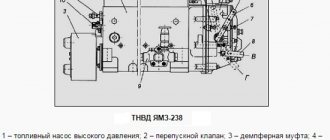
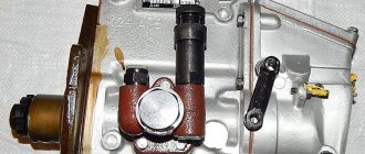
The main component of the diesel engine fuel system is the high-pressure fuel pump - injection pump. The function of the unit is to create operating pressure in the system, dosed fuel supply to the nozzles synchronously with the engine operating cycles at the beginning of the compression stroke into each individual cylinder, taking into account the operating modes of the power unit. The technical condition and adjustment of the unit directly affects the operation of the diesel engine and the power it creates.
Fuel injection pump of the MTZ 80 tractor
MTZ 80(82) tractors are equipped, depending on the year of manufacture, with fuel pumps in early configurations UTN 5 and later 4 UTN, 4 UTNM produced by the Noginsk Fuel Equipment Plant. According to the classification, these units are mechanical with an all-mode regulator and corrector, and have the same operating principle and design. The fuel pump of the MTZ 80 (82) tractor is installed on the left side of the machine in the front part of the engine compartment. The mechanical drive of the unit is carried out through the gas distribution gear from the engine crankshaft.
Injection pump brands for MTZ tractors
| Engine brand MMZ | Injection pump brand of old configuration | New fuel injection pump brand |
| D-240 | 4 UTNM-1111005 | 4 UTNI-1111005-20 |
| D-243 | 4 UTNM-1111005-110 | 4 UTNI-1111005-20 |
| D-241 | 4 UTNM-1111005-10 | 4 UTN-1111005 |
| D-242 | 4 UTNM-1111005-20 | 4 UTN-1111005-10 |
| D-244 | 4 UTNM-1111005-100-01 | 4 UTNI-1111005-30 |
| D-245 | 4 UTNM-T-1111005 | 4 UTN-T-1111005 |
| D-245.3, D-245.2 | 4 UTNM-T-1111005-30 | 4 UTN-T-1111005-30 |
| D-245.4, D-245.5 | 4 UTNM-T-1111005-20 | 4 UTN-T-1111005-20 |
| D-245L-83, D-245.1 | 4 UTNM-T-1111005-40 | 4 UTN-T-1111005 |
Characteristics of the fuel injection pump MTZ-80 of the D-240 UTN-5 engine
| High pressure fuel pump - injection pump of the MTZ tractor | |
| Catalog number | 4UTNI-1111005-20 |
| Application | MTZ series tractors |
| Engine | D-240, D-241, D-242, D-243, D-244, D-248, D-248.1, D-247.1 |
| Peculiarities | UTN, in-line |
| Drive type: injection pump | splined bushing |
| Factory | Noginsk |
| Analogs | PP4M9P1g-4201 (MOTORPAL, Czech Republic) |
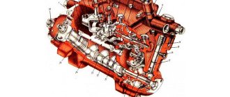
Injection pump device MTZ 80 Belarus
Diagram of the fuel pump UTN 5 diesel D-240
: 1 - housing; 2 - discharge valve; 3 - plunger pair; 4 - plunger; 5 — pusher bolt; 6 - cam shaft; 7 — splined bushing; 8 - mounting flange; 9 — booster pump; 10 — manual pump; 11 — air release plug; 12 - bypass valve; 13 — earring; 14 — regulator spring; 15 — corrector; 16 — breather; 17 — nominal bolt; 18 — regulator body; 19 — drain plug; 20 — control hole plug; 21 - plate; 22 — drain plug; 23 — bolt of maximum rotation speed; 24 — control lever; 25 — gear rack; 26 — ring gear; 27 - tightening screw.
1 - pressure fitting;
2 - clamps; 3 - spring; 4 - discharge valve; 5 — valve seat; 6 - gasket; 7 — plunger bushing; 8 - plunger pair; 9 - plug; 10 — ring gear; 11 — rotary sleeve; 12 — regulator cover; 13 — rack rod; 14 — spring lever; 15 — regulator spring; 16 — enrichment spring; 17 — main lever; 18 — corrector housing; 19 — corrector rod; 20 — adjusting screw; 21 - intermediate lever; 22 — nominal bolt; 23 - bolt; 24 — regulator body; 25 — load axis; 26 - heel; 27 - coupling; 28 — heel axis; 29 — lever axis; 30 — regulator weights; 31 — thrust ball bearings; 32 — drain plug; 33 — cargo hub; 34 — shock absorber block; 35 — washer; 36 — bearing cup; 37 — oil deflector; 38 — control lever; 39 - cam shaft; 40 - plug; 41 — eccentric drive of the booster pump; 42 — flange for mounting the booster pump; 43 — adjusting washer; 44 — mounting plate; 45 — pump housing; 46 — oil supply hole; 47 — roller nut; 48 — splined bushing; 49 — mounting flange; 50 — pusher with roller; 51 — pusher adjusting bolt; 52 — spring plate (lower); 53 — plunger spring; 54 — spring plate; 55 — rack; 56 — bolt for bleeding; 57 — channel for fuel removal; 58 — bypass tube; 59 — bypass valve body; 60 - plug; 61 — valve ball; 62 — hole for fuel supply; 63 — channel for fuel supply; 64 - cut-off hole; 65 — inlet hole of the plunger sleeve; 66 - pin; 67 — hatch cover; 68 — adjusting screw; 69 — gasket; 70 - filler plug; 71 — adjusting screw; 72 — corrector spring; 73 - tightening screw. The injection pump consists of the following main components: plunger pairs, housings, discharge valve, pushers, cam shaft, plunger drive mechanism. The fuel pump head and its housing are one piece and made of aluminum alloy. Principle of operation
A cast iron plate is attached to the front of the housing for mounting the pump on the engine, and at the rear there is a flange for mounting the regulator. All four sections of the pump are a miniature fuel pump, whose operating principle is as follows. As the cam shaft rotates, the cam protrusion runs up against the roller at a certain period of time and lifts the tappet. After the cam protrusion comes out from under the roller, the springs lower the pusher. Simultaneously with the pusher, the plunger rises and falls, thus producing a reciprocating movement in the cavity of the sleeve. As the plunger moves downward, fuel fills the space it vacated in the sleeve. During its upward movement, the plunger compresses the fuel and the pressure created opens the discharge valve, providing a path for the fuel to reach the injector. The cycle of suction and discharge is then repeated. The plunger rotation mechanism, which serves to change the fuel supply, consists of a rack and gear rims. The plunger bushings have rotary sleeves equipped with toothed rims. With its protrusions, the plunger fits into two longitudinal grooves of the rotary sleeve. A plunger spring is placed on the sleeve. Through the lower plate it rests against the pusher bolt, and through the upper plate it rests against the pump housing. The toothed rims of the sleeve are in constant engagement with the teeth of the rack, which moves in two bronze bushings. Using a rod, the rack is connected to the regulator levers and moves under their influence, turning the gear ring simultaneously with the plunger sleeve and thus changing the fuel supply. Tangential profile cams are placed on the cam shaft symmetrically to each other. Between the second and third cams there is an eccentric that drives the fuel boost pump. At the top of the rear part of the fuel pump housing of the MTZ 82 tractor there is a bypass valve through which excess fuel supplied by the fuel priming pump is returned to its suction chamber. Thus, the pressure in the channels of the D-240 diesel injection pump head is maintained in the range of 0.07-0.12 MPa (0.7-1.2 kgf/cm2). The pushers slide into holes in the horizontal partition of the fuel pump block. There is a hatch on the side wall of the housing, through which it regulates the uniformity of fuel supply across sections and, in fact, the fuel supply itself. A threaded hole is used to control the oil level in the pump housing. To communicate the internal cavity of the fuel pump housing with the atmosphere, a breather is used, equipped with an air purification filter made of elastic foam.
Operation of the fuel injection pump regulator
The parameters of the regulator's operating modes are set by adjusting the device mechanism and must correspond to the performance indicators of the power unit according to the manufacturer's data.
Start mode
Control lever 29 is set in the direction of maximum rotation speed until it stops at bolt 32. Lever 9 simultaneously stretches two springs 10 of the enricher and 15 of the regulator. Spring 15 presses the main rod 23 to the head of the “nominal” adjusting bolt 19, and the spring 10 of the enricher supplies the intermediate rod 22 with rod 14 in the direction of movement of the rack to increase the fuel supply. (Figure I) With an increase in rotation speed after starting the engine, the weights at the end of the shaft diverge under the action of centrifugal forces and, overcoming the force of the main spring 15 and the enrichment 10, move the coupling 5 back. In this case, the rod 22 moves, acting on the pump rack through the rod 14 in the direction of reducing the fuel supply until the idle speed is set. (Fig. II)
Scheme of operation of the operating modes of the fuel injection pump regulator
Work mode
When the engine reaches its maximum rotation speed, the centrifugal force of the regulator weights is balanced by spring 15 and the rack takes an intermediate position. In this case, the corrector rod 17 is in a recessed state, the spring of the enricher 10 is compressed, the rods 22 and 23 are pressed against each other and work as one whole. (Fig. II)
When the load on the engine increases to the nominal speed, the rotation speed decreases, as a result of which the centrifugal force on the loads decreases and the coupling ceases to act on the intermediate rod 22. The main rod 23 rests against the head of the “nominal” bolt and, under the action of the spring 15, the pump rack is moved in the direction of increase fuel supply. (Figure III)
Scheme of operation of the operating modes of the fuel injection pump regulator
When the rated speed level is reached, the movable equilibrium of the governor mechanism is established. The force of the spring 15 is balanced by the centrifugal forces of the loads, and the main rod 23 touches the head of the “nominal” bolt.
When a short-term load occurs that exceeds the rated load, the rotation speed of the engine and pump decreases sharply. The force of the loads on the intermediate rod 22 decreases. In this case, the spring 7 in the corrector pushes the rod 7 and rests against the main rod 23, as a result of which the intermediate rod 22 together with the rack under the action of the spring 15 moves in the direction of increasing the fuel supply. Thus, the engine torque increases and overcomes the load. (Figure IV)
Adjustment of the fuel supply when overcoming temporary loads in comparison with the supply at nominal speeds occurs within 15-22% and depends on the degree of exit of the rod from the corrector housing, as well as on the degree of tension of the spring 14.
Engine stop mode
To stop, the control lever 29 is moved all the way in the clockwise direction. In this case, lever 9, under the action of the regulator spring 15, moves the main rod 23 to the rear wall of the regulator body. Resting against the limiting bolt 18, the rod 23 carries with it the intermediate rod 22 and, accordingly, the pump rack back towards turning off the fuel supply.
Plunger pair
The plunger pair consists of a bushing and a plunger, which are the main working parts of the fuel pump. Thanks to it, the required amount of fuel is supplied to the engine cylinders under high pressure. The plunger and bushing are made of alloy steel, after which they are heat treated and form a precision pair. This design was implemented because during operation high pressure is generated in the pump, as a result of which tightness and vapor density are required to block the flow of fuel from the space above the plunger. The plunger pair cannot be disassembled and if one of the parts fails, the entire pair is replaced. The upper part of the plunger pair bushing has a significant thickening, since in this place it is exposed to serious pressure. The upper thickened part of the bushing has an end in the form of a step to allow it to fit into the socket of the pump housing. There are two windows in the upper part of the sleeve: bypass and suction. Fuel is cut off and bypassed through the bypass window, and fuel is supplied to the space above the plunger through the suction port. These holes are connected in the upper part of the injection pump with longitudinal channels. The bushing is secured against rotation by a pin that fits into the milled groove of the bushing. The falling out of the pins is blocked by the hatch cover. The bushing is located on top of the pump housing, and the discharge valve is pressed to its upper end. To ensure the required tightness, the contacting ends of the injection valve seat and bushings have a well-ground surface. Diagram of a plunger pair
: 1 - fitting; 2 — pressure valve spring stop; 3 — discharge valve spring; 4 — discharge valve seat; 5 - discharge valve; 6 - seal; 7 - bushing; 8 - plunger; 9 - rack; 10 — ring gear; 11 — rotary sleeve; 12 — upper plate of the plunger spring; 13 — plunger spring; 14 — lower plate of the plunger spring; 15 — coupling screw; 16 and 17 - suction and bypass windows. The plunger looks like a cylindrical rod, on the surface of which there is a pair of symmetrically placed spiral grooves, one of which is carefully processed and is designed to change the volume of fuel injected into the cylinder of the D-240 engine. When the edge of the bypass window of the bushing coincides with the edge of the groove, the pressure in the space above the plunger decreases sharply, and therefore the fuel supply to the injector stops. Another groove equalizes the specific fuel pressure acting on the side surface of the plunger during pump operation. On the plunger, below the cut-off edge, there is an annular groove where leaked fuel is retained, which is then used to lubricate the plunger pair. At the bottom of the plunger there are two protrusions to control its rotation and a head on which the spring plate rests.
Discharge valve
The discharge valve is used to disconnect the space above the plunger from the high pressure fuel line and sharply reduces the pressure in the fuel line when the plunger stops supplying fuel. The valve and seat are made of alloy steel. To create the required tightness, the seat and valve are carefully processed and adjusted to each other. Disassembly of discharge valves is not permitted. The valve moves in the seat with a cross-shaped shank, between the support belts of which fuel is passed. A spring mounted above the valve tends to press it against the seat. At the top of the valve there is a guide collar on which a spring is mounted, and its second end rests against the end of the bore of the pressure fitting. Between the seat cone and the valve shank there is a cylindrical groove called a relief belt.
Discharge valve
: a - beginning of fuel cutoff; b - valve is closed; 1 - discharge valve; 2 — discharge valve seat; 3 - unloading belt. When the plunger stops supplying fuel, a spring located under the valve moves it down. At the same time, the unloading belt first disconnects the high-pressure fuel line from the area above the plunger, and then, continuing to move along the hole of the valve seat, acting as a piston, it pumps out part of the fuel from the fuel line, thereby sharply reducing the pressure. Due to this action, the fuel supply suddenly stops.
Maintenance and adjustment of the injection pump of the D-240 MTZ 80 - 82 engine
Maintenance of the fuel pump consists of monitoring the oil level (every 120 hours of operation) and timely replacing it in the pump housing (every 480 hours). For more reliable operation of the injection pump on the latest modifications of the D-240 and D-240L engines, circulation lubrication of the pump from the engine lubrication system is used. Every 960 hours of engine operation, it is recommended to check the compliance of the fuel pump with the established parameters. If necessary, adjust the injection pump.
Operating principle of the ignition system
The ignition system is used for reliable and timely ignition of the combustible mixture entering the cylinder. It consists of a magneto, a spark plug and a high voltage wire.
The operating principle of this element is quite simple and reliable at the same time - when the working mixture enters the cylinder of the starting engine, it is ignited by means of an electric charge formed between two electrodes on the spark plug. For the highest quality charge, a fairly high voltage is required, approximately 10-15 kV, which is created in a special device - a magneto, which combines a number of functions - a breaker, an alternating current generator and a transformer.
The D-240 engines use a magneto with right rotation and a constant spark generation rate. The magneto drive comes from a rigid coupling half through the drive gear on the starting motor.
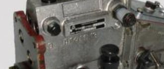
Checking (adjusting) the fuel pump
Before checking, it is necessary to ensure that the locking cone of the discharge valve is tight and that there is sufficient pressure in the pump section located in the upper cavity. Rotating the crankshaft, you need to move the regulator until the needle on the pressure gauge stops at 15 MPa. The engine is then stopped and the fuel supply is turned off using the control lever. When the pressure drops on the pressure gauge in less than 10 seconds, the valve is in good working order and can be used for further use. To adjust the exact angle at which fuel begins to flow, you will need to screw in/unscrew a special adjusting bolt. When unscrewing the bolt, the angle will increase, and when screwing it back in, it will decrease accordingly. Please note that one turn (turn) of screwing in/unwinding adjusts the engine speed by approximately 30-50 revolutions. When the bolt is loosened, the performance and throughput of the pump decreases proportionally, and when tightened, on the contrary, it increases. Let's look at how to install the fuel injection pump (4UTNI-1111005-20) on an MTZ tarctor with a D-240 engine. The MTZ D-240 fuel pump is marked 4UTNI-1111005-20 and has an in-line design with a splined bushing.
Installation of a fuel pump on tractors MTZ-80 and MTZ-82
1
.
Remove the housing from the hole in the front distribution panel. 2
.
Determine the position of the wide tooth of the splined flange of the fuel pump drive gear and insert the splined bushing of the fuel pump into the splined washer of the pump drive gear. 3
.
Bolt the fuel pump to the engine. 4
.
Attach the fuel supply control rod to the regulator lever so that when the fuel supply control lever is in the rearmost position, the regulator lever occupies the position corresponding to the maximum fuel supply. 5
.
Connect the high pressure fuel lines to the injector and pump head fittings according to the engine operating order. 6
.
Connect the fuel lines to the pump. 7
.
Open the supply valve and fill the engine power supply system with fuel. 8
.
Pump fuel with a manual pump until a stream of fuel without air bubbles appears from the drain pipe. 9
. Close the purge valve and tighten the handle of the manual pump.
Device
When planning to repair the MTZ fuel injection pump, you should familiarize yourself in more detail with the design of such an element. It is distinguished by a minimum number of elements and high reliability, which makes it possible to significantly simplify the procedure for adjusting the pump, as well as troubleshooting. The main components of this unit are:
- plunger pairs;
- frame;
- pressure type valve;
- pushers;
- camshaft;
- plunger drive mechanism.
The pump head and housing are a single element made of high-strength aluminum alloy. The design of the unit provides that a special plate is placed on the front part of the housing, which is used to mount the product directly on the engine. When figuring out how to remove the injection pump from the MTZ 82, it should be noted that to do this it is enough to remove the mounting bolts.
The back of the plate is equipped with a special flange, which is used to install the regulator. The principle of operation of the product is extremely simple, it involves the following algorithm of actions:
- The cam shaft begins to rotate, lifting the pusher with the help of a roller.
- The pusher moves down together with the plunger.
- Fuel fills the space in the sleeve vacated by the descent of the plunger.
- When the element returns to its original state, pressure is created, due to which, with the help of a valve, a portion of fuel flows through the nozzles.
This cycle is repeated at certain intervals, which allows you to maintain the fuel level necessary for proper engine operation.
Installation of ignition (injection timing) MTZ 80
1
.
Disconnect the high pressure fuel line from the fitting of the first section of the fuel pump. 2
.
Screw the momentoscope onto the fitting using a nut. 3
.
Place the pointer arrow on the water pump housing so that its end is at the outer surface of the fan pulley. 4
.
Check the position of the fuel control lever to the maximum value. 5
.
Pump diesel fuel with a manual pump by opening the purge valve. 6
.
Remove some of the fuel from the momentoscope tube. 7
.
Unscrew the mounting pin from the hole and insert its unthreaded end into the same hole until it stops. 8
.
Slowly rotate the crankshaft by the crank clockwise until the pin fits into the recess. This will correspond to the position of the piston of the first cylinder, at which it will not reach c. m.t. by the value of the feed advance angle. Make a mark on the surface of the pulley opposite the end of the pointer arrow. 9
.
Rotate the crankshaft counterclockwise one-half turn and then, rotating clockwise, monitor the position of the fuel level in the torque scope. When the fuel begins to rise in the glass tube of the momentoscope, stop rotating the crankshaft. The pointer arrow should coincide with the mark on the surface of the pulley. If the pointer arrow does not coincide with the mark, it is necessary to adjust the feed advance angle. 10
. Remove the momentoscope, install a high-pressure fuel line on the fitting of the first section of the pump and remove the indicator arrow.
Maintenance Recommendations
You can logically calculate that as the fuel supply to the engine increases, its torque also increases, which naturally increases the rated power of the D-240 engine. In addition, the speed of operation is increased to the limits of its capabilities. Changing the oil in the UTN pump is necessary only after disassembly and repair, and is not necessary for everyday use of the tractor. Filling of diesel oil should be done through the injection pump crankcase in a volume of 150-200 ml.
Checking the injection advance angle
After starting, check the operation of the engine in different modes. In case of unstable or hard operation at high speeds, knocking and detonation, black smoke and incomplete combustion of fuel, the injection timing is checked and adjusted. Install the momentoscope on the first section of the pump and monitor the coincidence of the moments when the probe enters the hole in the flywheel and the start of fuel supply to the pump section. The moment of supply before the probe coincides indicates a large advance angle, but if the fuel supply does not start when the probe hits, the injection is late. If the injection timing does not match, correction is made by turning the injection pump shaft. Also open the pump cover, unscrew the two bolts securing the adjusting washer with the bar. To increase the advance angle, turn the shaft clockwise, and in the opposite direction, reduce the injection advance angle. Moving the shaft position by one adjustment hole on the washer corresponds to 3 turns of the diesel crankshaft. By turning the injection pump shaft in the desired direction until the holes on the washer and the gear flange coincide, the injection angle is changed. Assembly is carried out in the same order - install the washer with bolts on the bar in the matching holes.