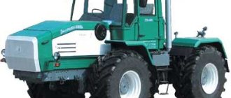
Tractor technical characteristics
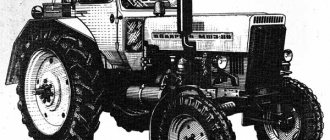
The MTZ 80 tractor gained its popularity due to several factors. Firstly, the machine is constructed from high-quality reliable parts, which, coupled with excellent assembly, guarantee long service life in any conditions. Secondly, the MTZ 80 tractor has a simple device, which makes its operation, maintenance and repair quite simple. Thirdly, the equipment is equipped with all-terrain running gear. This is especially true for the front and rear axles, which are characterized by increased reliability due to the use of durable parts. The main characteristics of the machine include:
- Reliable engine D-240, 80 hp. With.;
- Ability to transport loaded trailers weighing up to 1.5 tons;
- Ability to move in one of 18 forward and 4 reverse speeds;
- The wheel track in the front part is from 120 to 180 cm, in the rear part – from 130.5 to 210 cm;
- Physical weight – 3.16 tons;
- Speed – from 1.1 to 34 km/h;
- Ground clearance – 47 cm;
- The radius of movement when cornering is 4.05 m;
- The presence of a modified hydraulic system that increases comfort when operating the tractor.
The MTZ 80 tractor has relatively small dimensions. The length of the machine is slightly more than 3.8 and the width is 1.97 m. The height of the tractor is 2.47 m.
It is also important to note the presence in the design of the tractor of electrical wiring that has been completely redesigned compared to previous models. As a result, the tractor controls and instruments operate stably even under heavy load of the unit. Compared to the previous machine - MTZ-52, the MTZ 80 tractor is equipped with modified relays, as we are told by the drawings of the machine's electrical circuit in the documents for the tractor.
Of course, operating the machine is not without some minor problems. Often owners are faced with the issue of not being able to start the tractor. In this case, you should try an alternative option, that is, try the “launcher”. However, before you start it from the starter, you need to make sure that there is no blockage in the starter - it is quite possible that the car will not start due to the presence of dirt inside the unit.
Another common problem is gearbox jamming. Often the gearbox does not allow you to change gear because one of the gears has fallen off its seat. In such a situation, you should check the integrity of the transmission and install all the fallen elements back into place.
In general, the MTZ-80 model shows itself as a reliable unit for performing a wide range of different jobs. The owner can install chains on the wheels of the machine, use various attachments for planting, collecting and transporting crops, and use a loader.
Below we will look at what the MTZ 80 tractor consists of, and we will also study in detail the design of the main components of the agricultural machine.
Overhaul of the D-240 engine of the MTZ-82 tractor. Complete assembly and disassembly
Repairing the D-240 engine involves dismantling it from the tractor and replacing the cylinder block with a new one or a repaired old one if cracks appear on the block, the gap in at least one crankshaft journal-liner interface is exceeded, or there are emergency knocks on the connecting rod or main bearings.
After measuring the main engine parts (piston group, connecting rod bearings, cylinder liners), it is determined what type of repair is to be carried out - major or current.
First you need to check the condition of the crankshaft journals and connecting rod bearings. To do this, remove the oil pan, oil pump, oil lines, connecting rod caps and measure the diameter of the crankshaft connecting rod journals. The diameter of the connecting rod journals is measured in two planes - perpendicular to the longitudinal axis of the connecting rod and parallel. If the ovality of the journals is greater than permissible or their diameter is less than the lower tolerance of the corresponding size group, the crankshaft must be removed and ground to the next repair size.
Removing the oil pump: 1 - discharge pipe; 2 - oil pump.
Measuring the diameter of the crankpins of the crankshaft: 1 - micrometer; 2 — connecting rod journal.
Removing the crankshaft
Removing the rear support of the crankshaft: 1 - rear support; 2 — rear support mounting bolts.
In fact, in addition to the repair values (P1, P2, P3), alternating every 0.5 mm and set by the engine manufacturer, if wear is insignificant, the crankshaft journals are ground to additional dimensions (D1, D2, D3), alternating together with the repair dimensions after 0.25 mm. In a similar way, liners of repair sizes are bored to accommodate additional ones. The permissible ovality of the engine crankpins should not exceed 0.06 mm.
Repair and nominal dimensions of the connecting rod journals of the crankshaft of the D-240 engine
| Designation of size group | Size size, mm |
| H1 | 68,16-68,17 |
| H2 | 67,91-67,92 |
| D1 | 67,66-67,67 |
| P1 | 67,41-67,42 |
| D 2 | 67,16-67,17 |
| P2 | 66,91-66,92 |
| D3 | 66,66-66,67 |
| P3 | 66,41-66,42 |
If the connecting rod journals have acceptable dimensions, then continue disassembling the D-240 - remove the cylinder head and dismantle the pistons and connecting rods assemblies. To determine whether replacement of the connecting rod bearing shells is necessary, measure the diameter of the connecting rod bearing bore with the cap and shell assembly tightened. The initial clearance in the connecting rod bearings is 0.05-0.12 mm, the permissible clearance is no more than 0.3 mm.
Removing the cylinder head cover cap
Removing the cylinder head
Removing the cylinder head cover
Removing the rocker shaft assembly and disconnecting the pipelines
Measuring the diameter of the connecting rod bearing hole: 1 - indicator bore gauge; 2 — connecting rod assembly with liners.
In cases where the surface of the liners is in satisfactory condition, the main reason for their replacement will be the value of the diametrical clearance in the bearing. When visually inspecting the liners, check that there are no scuffs on the antifriction layer, inclusions of foreign material, or chipping of the antifriction material.
Cylinder head repair
The main defects of the cylinder head (cylinder head) are: wear of the internal surfaces of the guide bushings, seats and working chamfers of the valves; warping of the parting plane; burnout of seats for seals of glasses or nozzles; cracks in valve seat bridges.
During the technical examination, they are guided by the basic values and adjustment data of the D-240 cylinder head parts and the gas distribution mechanism.
Basic adjustment data and indicators of the gas distribution mechanism and cylinder head of the MTZ-82 engine
| Valve stem protrusion, mm: | |
| nominal | 56 |
| acceptable | 57,2 |
| Valve movement, mm: | |
| nominal | 10,2 |
| acceptable | 9,0 |
| Deviation from the flatness of the head surface, mm, no more | 0,15 |
| Valve plate sinking, mm | |
| nominal | 10,2 |
| acceptable | 9,0 |
| Permissible inner diameter of valve sleeve, mm | 11,10 |
| Permissible compression force (elasticity) of external valve springs up to working length | 148 |
| Working length of outer spring, mm | 54,0 |
| Permissible compression force (elasticity) of internal valve springs up to working length, N | 74 |
| Working length of the internal spring, mm | 48,5 |
| Permissible valve stem diameter, mm | 10,85 |
| Inner diameter of rocker arm bushing, mm | 19,02-19,05 |
| Rocker axis diameter, mm | 18,98-19,00 |
The recession of the valve plates in the head seats can be determined without dismantling it from the cylinder block by measuring the protrusion of the suction valve stems relative to the surface of the head. To do this, it is necessary to set the pistons one by one to the top dead center of the compression stroke and measure the distance from the end of the valve stem to the head. If the valve protrudes to an unacceptable amount, this indicates that the valve plates and their seats are worn out.
Location of cylinder head parts: 1 - pipe; 2 - pipe; 3 — breather body; 4 - tank; 5 - cap; 6, 8 — gaskets; 7 — head cover; 9 — rocker arm; 10 - axis; 11 — cylinder head; 12 — head gasket; 13 — pusher; 14 — rod; 15 — exhaust valve; 16 — inlet valve; 17 — valve springs; 18 — valve plate; 19 — hairpin.
You can also set the degree of development of the camshaft cams. To do this, rotate the engine crankshaft until the valve is fully open (with the thermal clearance set for a cold engine) and measure the distance from the end of the valve stem to the head. The movement of each valve can be determined by the difference in distance measured with the valves fully open and closed. If the valve movement is below the required value, the camshaft should be replaced.
Measuring the deviation from the flatness of the cylinder head surface: 1 - straight edge; 2 — cylinder head; 3 - dipstick.
Upon completion of all measurements, remove the head from the engine and continue further inspection. Measure the deviation from the flatness of the head surface. If the deviation from flatness is exceeded, the head must be replaced; If the deviation is within the acceptable range, then check the condition of the valve seats by checking the seating of the new valve disc. If the valve plate sinks to unacceptable values, the head is replaced; If everything is normal, then disassemble and repair the head.
Determination of plate sinking: 1 - valve; 2 — cylinder head; 3 — depth gauge.
Removing valve cotters and valve springs: 1 - cylinder head; 2 — valve spring; 3 — device OR-9913.
Valve springs and valve cotters are removed using a special device OR-9913. If there are cracks on the valve seat, replace the head. The dismantled valves are marked, and then the diameter of the stem circumference is measured and the bending of the stem and the runout of the valve plate are checked.
Measuring the diameter of the valve stem: 1 - valve; 2 - micrometer.
Measuring stem bend and valve disc chamfer runout
The bending of the rod relative to the valve axis and the chamfer runout should not be more than 0.03 mm. If there are traces of burnouts, wear, or cavities on the valve chamfers, the working surface of the chamfers is ground on R-108 or OR-6686 machines. The intake valve chamfer is ground at an angle of 60 degrees, and the exhaust valve at 45 degrees. After detecting traces of wear, the width of the cylindrical part of valve plate A, and the width of the ground matte strip on the chamfer of valve B, should be no more than 2 mm.
Grinding the working surface of the valve chamfer
Measuring the diameter of the valve sleeve hole: 1 - indicator bore gauge; 2 — guide sleeve; 3 - cylinder head.
Pressing out the guide bushing
Pressing in the valve guide bushing: 1 - guide bushing; 2 - valve; 3 - cylinder head.
Machining the valve seat in the cylinder head
The valve guide bushing is replaced when the surface of the hole for the valve stem is worn out to an unacceptable diameter or when the bushing fits loose in the head. Before replacement, the guide sleeve must be pressed out. The new bushing is selected to the greatest tolerance on the outer diameter and is lubricated with epoxy glue without filler, and then pressed into the head using a special bolt.
As soon as the guide bushings are installed, it is necessary to process the valve seat with the OPR-1334A grinding device. If there are burns, scratches and holes on the working chamfer of the seat, you should grind the original chamfer until the defects are removed and check the seat for sinking of the new valve plate. The upper edge of the working chamfer of the seat in the cylinder head is processed with a grinding wheel with a cone angle of 60 degrees, and the lower edge - 150º. The width of the working chamfer of the seat for exhaust valves should be 1.5-2.0 mm, and for intake valves - 2.0-2.5 mm.
After processing, the valve seat and valve plate must be ground in. During the repair of 1-2 valves, grinding is carried out with a pneumatic device 2213, using a paste made from a mixture of M20 micropowder with motor or industrial oil.
During lapping, the valve is lifted and rotated from time to time. Periodically inspect the condition of the grinding chamfers of the valve and seat. The upper edge of the matte strip of the working chamfer must be located at a distance of at least 0.5 mm from the cylindrical part of the valve disc. If the matte strip is found significantly above or below this distance, the seat is again processed with grinding wheels and grinding is performed.
Before assembling the valves, you should check the compression force and length of the valve springs on the MIP-100 device. If the spring parameters are unacceptable, they must be replaced. Sometimes, to compensate for the compression force and length of the springs, washers are placed under them, the thickness of which can be calculated using the formula:
— for the exhaust valve A=B-1.8 mm, where B is the valve sinking, measured after repairing the seat; — for intake — A=B-1.3 mm.
When assembling the valve, make sure that the protrusion of the crackers above the plane of the spring plate is no more than 0.5 mm, and the sinking does not exceed 1.3 mm. In order to check the valves for leaks, the exhaust and inlet channels of the cylinder head must be filled with kerosene, which should not leak for one and a half minutes.
Before installing the rocker arm axles, check their technical condition. If depressions exceeding 0.3 mm are found on the rocker strikers, the surface of the striker should be sanded until the defects are corrected. Deviation from parallelism of the working surface of the rocker arm is allowed no more than 0.05 mm. If necessary, check the diameter of the holes in the rocker arm bushings. The gap between the rocker arm axis and the bushing should be no more than 0.15 mm.
Tractor engine design
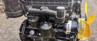
The engine of the machine belongs to the class of 4-cylinder, four-stroke engines with a water cooling system for the tractor.
It was created specifically for the line of these tractors at the same Minsk Tractor Plant. The operating volume of the engine is approximately 4.75 liters. Thanks to high-quality electrical equipment and a semi-separate combustion chamber, the rated engine power is 80 hp. s., and torque – 2200 rpm. The weight of the diesel engine is 428 kg. Some tractor models are additionally equipped with a pre-heater PZHB-200B. To start the machine, it is equipped with an electric starter and a carburetor starting motor. The design also includes a starter locking device, which must be used to hold the tractor in place when the engine is running.
To extend the life of the engine, the manufacturer recommends inspecting and servicing it every 240 operating hours. The manufacturer does not recommend using the heater unless necessary, as this negatively affects the stability of engine torque.
Preparing the MTZ-80 tractor for work - a note for beginners
Each model of MTZ-80 tractors leaves the factory fully equipped for further work. Each unit comes with a full set of spare parts, tractor driver’s tools, detailed operating instructions and additional accessories. However, before starting the tractor, the farmer still has to perform a number of procedures aimed at facilitating the start of the engine and other mechanisms of the agricultural machine. Their list includes:
- Before starting, you need to thoroughly wash the tractor;
- After this, you will need to remove the standard batteries and bring them into working condition;
- Next, you need to remove the protective polyvinyl chloride covers;
- Then you will need to install the drain valves of the standard radiator cylinder block on the tractor;
- In accordance with the lubrication table, you need to lubricate the rubbing components and mechanisms of the tractor;
- Next, you need to fill the fuel tank with settled fuel;
- After this, you need to fill the engine cooling system with clean water;
- Next, you need to check the pressure in the tractor tires, as well as in the hydraulic system pipes;
- At the end, you will need to install charged batteries and widen the tractor track to 140 cm. The video will clearly demonstrate the preparation of the Belarus MTZ-80 tractor for work.
Completing all of the above procedures before each cold start of the engine will extend the life of the MTZ-80 tractor and eliminate its breakdown. Thanks to this, repairs to the unit will need to be performed much less frequently.
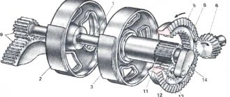
Features of the unit gearbox
The domestic tractor is equipped with a 9-speed manual transmission. The design also includes a reduction gearbox, which makes it possible to move at a total of 18 forward and 4 reverse speeds. At the buyer's request, the tractor can be equipped with a creeper, installed next to the hitch mechanism.
Often, vehicle owners hear knocking noises coming from the gearbox. If they disappear when working in other gears, then this is a direct sign of wear on some gears or chipping of their teeth. To finish the job without damaging the tractor even further, you will need to immediately replace the cutter with an element with less weight. At the end of the work, you need to replace the worn gears.
Some tractors manufactured before 1985 were equipped with a hydraulically controlled gearbox and the ability to change speeds at full load. Such machines made it possible to turn on any of 4 speeds located in one of 4 ranges. Provided the clutch was adjusted correctly, the clutch did not need to be depressed when shifting.
The rear axle of the MTZ-80 is equipped with a hydraulic differential locking function. The selection of the locking mode is available on the tractor instrument panel.
Possible malfunctions of the MTZ gearbox
Problems when starting off and with steering in motion associated with gearbox failure can be divided into two groups:
- Difficulties in fixing the selected speed (poor retention, “knocking out” the gear, etc.).
- Extraneous sounds made by the gearbox when shifting gears or while the tractor is moving.
The first stage of the gearbox, which doubles the available speeds, complicates the design of the box. Externally similar symptoms can be caused by the breakdown of various parts inside the unit; an accurate diagnosis can be made after partial or complete dismantling of the gearbox. Problems with the gearbox are the same for MTZ-80 with one drive axle and MTZ-82 with two axles.
Bearings.
Knocking out the speed
A shift out of gear while driving can be caused by problems with the shift forks, retainer springs, shafts, or bearings. If the gears are not properly engaged, the lever may return to the neutral position.
Impossibility or poor gear engagement
The problem with turning on speeds can be caused by the same reasons as their spontaneous switching off or switching, i.e. with defects in forks or retaining springs. The distance between the gear shift bars should not be more than 1.6 mm. The second source of problems with gear shifting is a malfunction of the clutch mechanism. The tractor may stall when starting due to defects in the fuel supply control system.
Rumble and grinding noise when the gearbox operates
Extraneous sounds when the gearbox is running can be of 2 types:
- constant (hum or noise);
- discrete (knock).
The presence of constant noise indicates wear of the shaft mounts. If the problem is not corrected, the shaft may break off the mounting and jam the transmission. Another source of persistent noise can be bearing wear. The reason for the simultaneous occurrence of noise and free play of the reduction gear control lever may be wear of the fork. Uncharacteristic sounds in the final drive gearbox may indicate a malfunction of the front axle.
Breakdown of the gearbox shift mechanism
A malfunction of the gear shift unit can result in play, which makes it impossible to set the lever to the desired position. The reasons may be:
- deformation of the springs during operation, as a result of which, in a compressed state, their length exceeds the maximum permissible;
- wear of shift forks;
- broken grooves of sliding carriages.
If there are signs of wear on the tip of the MTZ gearbox shift lever, it must be replaced.
Tension and compression deformation of a spring.
Tractor control and chassis
The front axle of the tractor is semi-rigid, of the balanced type and follows all the unevenness of the road when driving, regardless of the position of the frame and rear axle of the machine. The rear axle is rigid, the wheels are secured using clamp connections to the drive axles. Thanks to this, the driver can immediately set the track required for work, choosing an indicator in the range from 140 to 210 cm. The width of the front track is adjusted gradually in increments of 10 cm.
The tractor is equipped with disc brakes with a separate electrical circuit. This design of the brakes makes them independent of the overall design of the tractor. Therefore, if something in the overall scheme of the tractor fails, the brakes continue to perform their function.
MTZ-80 is equipped with hydraulic power steering. This mechanism works on the same principle as power steering on any car: pressure is created in the oil pump, after which the hydraulic booster directs the required amount of oil to the hydraulic cylinder.
Overview of the MTZ-80 cabin
Models with a small cabin are in great demand among buyers due to their compactness. Their cabins are made of thin sheet steel. The inside of the cabin is upholstered with soundproofing material. It is attached to the structure using four rubber shock absorbers, which soften shaking and vibration.
During operation, the driver has a good overview of the area. Windshield wipers are installed under the front and rear windows. The rear window and roof can be opened to allow air flow. For comfort when boarding and driving, the tractor is equipped with two steps and handrails on both sides of the cab.
The tractor driver is provided with a comfortable seat with the ability to adjust the backrest tilt. The height of the chair is adjustable vertically and horizontally.
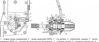
In front of the seat is a front panel with controls. Under the dashboard there are pedals with a separate brake. To the right of the steering wheel are the hydraulic system control levers and the PTO start lever.
Installation of attachments
The tractor is equipped with a three-point rear linkage design, made according to the classical design. The device consists of 1 central, two longitudinal rods, braces and a power cylinder that raises and lowers attachments.
To manage inventory, the machine is equipped with a separate hydraulic device, which consists of the following parts:
- Gear type oil pump;
- Motor driven;
- Hydraulic distributor with three sections;
- 2 or 3 cylinders.
MTZ-80 is operated with various attachments. For work you can use:
- Kuhn;
- Potato digger;
- Plow;
- Harrow;
- Hiller;
- Kosarka;
- Snow shovel and much more.
If necessary, the tractor can be equipped with a trailer. The design of the machine allows you to connect a generator.
Areas of operation of agricultural machinery
A fully serviceable MTZ-80 tractor can be operated with different types of mounted implements.
Their list includes:
- plow, harrow, cultivator, rototiller - the width of the equipment should not exceed 2 m, and the weight should not exceed 1 t;
- seeder, sprayer, rake, potato planter, potato digger with a weight of up to 0.8 tons;
- blade up to 1.5 m wide and weighing up to 1.3 tons;
- kun - its total weight together with cargo should not exceed 1.8 tons.
The MTZ-80 tractor can also be equipped with drills, branch choppers, mulchers and trailers, the total weight of which, including luggage, does not exceed 2 tons.
Popular unit modifications
As is the case with many popular tractors, the MTZ-80 received several modifications that were intended for certain jobs. The most famous of them include:
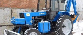
- MTZ-80.1 - an enlarged cabin and improved rear-wheel drive made this tractor popular among owners of land located on slopes. This model had reliable spare parts and a modernized gearbox. It made it possible to operate the tractor without any preparation for work;
- MTZ-80L is a tractor designed for forestry work. It was used mainly to fight fires and restore forests. This unit was equipped with a diesel engine with a power of 60 hp. With. Among the disadvantages is the need for frequent repairs of the chassis.
Each of these representatives is still popular, because, at a low cost, these machines have high reliability and excellent performance.
How to disassemble the MTZ-80 box
Depending on the external signs of a malfunction, the gearbox must be partially disassembled or completely dismantled. The sequence of actions for complete dismantling of the MTZ gearbox in the repair scheme described in the instructions for the tractor provides the following steps:
- transmission oil drain;
- disconnecting the box assembly from the tractor body;
- disassembling the gearbox.
If a number of transmission , you can disassemble without complete dismantling; this method is provided for unclear gear shifting, when at the first stage it is enough to dismantle the transmission control knob and check the condition of the unit.
Disassembling the MTZ-80 gearbox lever
You can check the suitability of the shift knob for further use without dismantling the gearbox, for which you need to perform the following steps:
- remove the lever by first removing the floor and disassembling the hinge socket;
- remove the plate with forks, visually determine which of them require replacement;
- inspect the suitability of the gear shift knob for further use;
- if the forks are bent and loose, and their working sides are not parallel, it is necessary to disassemble this unit and replace the worn parts.
Such repairs can eliminate only part of the possible problems associated with poor engagement and gear shifting. A complete inspection of the unit requires complete disassembly of the gearbox.
Disassembly procedure
In addition to keys and screwdrivers, the following fittings are required to remove the tractor gear shift mechanism:
- puller;
- hammer;
- metalworker's beard (beater);
- bronze knockout.
After disconnecting the assembly from the body and dismantling the plug block, you should:
- remove the retaining ring and gear from the input shaft, then remove the second ring and dismantle the bushing and gear No. 4;
- Having previously knocked out the pin, remove the internal PTO drive shaft (power take-off shaft);
- Having unscrewed the bolts and removed the socket, remove the second range drive gear complete with the cup and bearings from the housing;
- remove the input shaft to facilitate disassembly of a manual transmission operating according to the scheme (9F+2R);
- remove the intermediate shaft;
- remove the secondary shaft;
- prepare to remove the reverse and low gear shaft by removing the retaining ring and bearings;
- remove the reverse and low gear shaft from the housing;
- press out the bearing cup.
After removing the shafts from the gearbox, remove the gears from them and disassemble the remaining parts, removed entirely.
Defects of gearbox parts
After complete disassembly of the transmission, it is necessary to visually inspect all components and make a decision on their suitability for further use. In order not to miss metal defects, it is recommended to wash the components in kerosene or diesel fuel and dry them before inspection.
Recommendations for rejecting box elements:
- The housing must be replaced if cracks are detected.
- It is necessary to replace with new broken glasses in the body of the box.
- Instead of bent forks, as well as with non-parallel cheeks, new ones should be installed.
- Bearings should be checked by rotating the outer race relative to the inner race.
- You cannot install a gearshift lever with a worn tip.
You can begin installing the gearbox only after checking all the parts and obtaining new ones to replace those unsuitable for use.