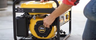
Power steering MTZ-82 (power steering) is installed on agricultural machinery in order to reduce the effort the tractor driver makes to turn the steering wheel. At the same time, the maneuverability of the tractor increases under any conditions in which it is necessary to work.
When moving the power steering of the tractor, the MTZ is connected and functions not only when the steering wheel is turned, but also under the influence of the movement of the front wheels, which oscillate due to uneven ground. At the same time, the MTZ power steering affects the other side, relative to the rotation of the wheels. This has a good effect on the movement of agricultural machinery in a straight line and significantly reduces the transmission of vibrations and other adverse effects from the front wheels.
4.1.1. Steering repair. Power steering
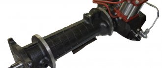
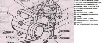
Rice.
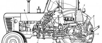
2.3.10. Power steering (power steering): a - general view; 1 - amplifier housing; 2 - rail; 3 — power cylinder; 4 - piston; 5 - safety valve; 6 — spool; 7 - rotary shaft; 8 — upper cover of the power steering housing; 9 — adjusting bolt of the rotary shaft; 10 - sector; 11 — worm of the steering mechanism; 12 — differential lock sensor; 13 — drain pipe; 14 — steering bipod. The main defects of the power steering include: wear of the worm shaft splines and sector teeth, gear rack, wear and violation of the tightness of the safety valve, wear and violation of the hydraulic tightness of precision parts (spools, plungers, sleeves). If, in the process of checking the technical condition of the units of the hydraulic steering control system of the tractor, faults are identified that cannot be eliminated by carrying out normal adjustment operations, the power steering is removed from the tractor and disassembled for technical examination and replacement of parts. The sequence of basic operations and the correct techniques for disassembling, assembling and adjusting the power steering are shown in Fig. 2.3.9 - 2.3.30.
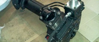
Before removing the power steering, drain the hydraulic fluid and unscrew the steering shaft nut 4 .
Rice. 2.3.9. Compressing the steering bipod: 1 - extension; 2 — steering bipod; 3 - drain pipe; 4 — rotary shaft nut.
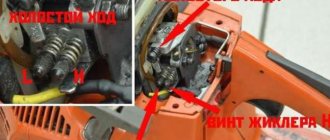
Rice. 2.3.11. The relative position of the differential lock sensor parts: 1, 10 - bolts; 2 - cover; 3 - spring; 4 - spool; 5 - pusher; 6 - ring; 7, 9 — housings; 8 - valve; 11 - tap.
Rice. 2.3.12. Removing the oil supply tube from the distributor: 1 - oil supply tube; 2 — power steering housing; 3 - mesh filter; 4 - pressure reducing valve.
Rice. 2.3.13. Removing the rotary shaft: 1 — power steering housing; 2 - rotary shaft with a sector.
Fig.Fig. 2.3.14. Unscrewing the nut securing the sector to the rotary shaft.
Fig.Fig. 2.3.15. Pressing the sector from the rotary shaft.
Rice. 2.3.16. Removing the differential lock sensor.
Rice. 2.3.17. Removing the differential lock sensor cover.
Rice. 2.3.18. Removing the retaining ring and rack.
Rice. 2.3.19. Removing the power steering cylinder.
Rice. 2.3.20. Unscrewing the fastening nut and removing the piston.
Rice. 2.3.21. Removing the distributor.
Rice. 2.3.22. Removing the safety valve and worm assembly.
Rice. 2.3.23. Removing the worm bearing retaining retaining ring.
Rice. 2.3.24. Pressing worm bearings.
Rice. 2.3.25. Pressing out the rotary shaft bushing: 1 - bushing; 2 - axle; 3 — puller screw.
Rice. 2.3.26. Tightening the castle nut, worm nut.
The tightening torque is no more than 20 N.m.
When assembling the power steering, special attention is paid to the tightening torques of the nuts, the correct alignment of the marks of the rotary shaft, sector and rack, and the adjustment of the vertical movement of the rotary shaft.
Rice. 2.3.27. Alignment of marks on the end of the rotary shaft spline: 1 - marks; 2 - rotary shaft; 3 - sector.
Rice. 2.3.28. Combination of marks on the middle tooth of the secret shaft and the sector: 1 - marks; 2 - rail; 3 - sector.
Rice. 2.3.29. Tightening the piston nut.
Tightening torque 120N.m.
Rice. 2.3.30. Adjusting the vertical movement of the rotary shaft: 1 - adjusting bolt; 2 - lock nut.
Screw the bolt until it touches the rotary shaft, and then unscrew it 30 - 45° and secure it with a locknut.
Disassembly, assembly and adjustment operations performed during the repair of power steering are quite complex and require the use of control and testing equipment after completion of assembly. The assembled power steering is tested on the control and testing stand KI-4896M. During the tests, the free play of the steering wheel is checked with the vertical power steering shaft fixed, which should be within 4 - 6°, as well as the operation of the hydraulic booster under load at an input pressure of 5 - 6 MPa. The force on the steering wheel rim should not exceed 50N.
Power steering on MTZ-80: device, malfunctions and methods of elimination
On Minsk MTZ-80 (82), equipped with a D-240 engine, a 70-3400020 power steering is installed, which is produced by the Bobruisk Plant of Tractor Parts and Assemblies (BZTDiA).
Let's look at the diagram 70-3400020 in section. The unit is placed in a housing (2) made of cast iron, which is installed on the machine frame between the front wall of the hood and the diesel engine radiator. It houses the main steering mechanism - these are a connected worm (5) and a sector (4); as well as hydraulic units of the system: hydraulic pump NSh-10-L-U GOST 8753-71, power cylinder, safety valve, spool valve, and hydraulic tank.
If there is a malfunction in the power steering system for any reason, stiff steering occurs. Let's look at the main types of power steering faults, how to fix them and improve them yourself.
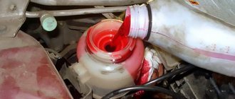
- If foam forms in the system, the reasons may be the following:
- due to the fact that the fluid level in the power steering tank is low (then you should check the level and add fluid if necessary);
- air has entered it (inspect the suction pipeline (20) in order to identify places where air is leaking, carry out repairs, put washers on the connection, replace the seals).
How to improve the power steering with your own hands by placing washers under the spool is shown in the video below.
Repair of the steering control of the MTZ-80 tractor
For high-quality and reliable operation of the MTZ-80 cargo vehicle, manufacturers have included power steering - power steering - in the tractor design. It is a unit whose function is to transmit rotations to the steering bipod, which the structure receives from the steering wheel. Rotations make turning easier when driving on rough roads. Strengthening the steering control of the MTZ tractor is achieved by increasing the pressure that occurs due to fluid injection.
During a trip, problems may arise inside the unit that can lead to failure of the structure. To prevent such developments, it is worth understanding how to adjust and repair power steering.
Hydraulic booster - purpose and device
Hydraulic power steering not only reduces the effort exerted by the tractor driver to control the vehicle, but also significantly increases its maneuverability, especially when passing difficult sections of the road. It is an intermediate unit that performs a hydraulic and mechanical connection between the steering wheels, the angle of rotation of which is proportional to the existing angle of rotation of the steering wheel, and the steering wheel itself.
The mechanism of the unit (a helical-type sector and a two-start worm), as well as its hydraulic units (distribution unit, steering hydraulic cylinder, locking sensor and power steering tank) are assembled into a single unit installed in front of the radiator. From the outside, the hydraulic booster is protected by the tractor lining.
Power steering hydraulics includes the following components:
- A tank used for working fluid. Its role is played by the cavity of the hydraulic booster housing;
- Gear pump mounted on the left side of the engine. It is driven by gears on the distributor;
- A power cylinder, which is responsible for transmitting movement directly to the steering trapezium;
- Ball type safety valve;
- Differential lock sensor.
How does power steering work?
The power steering housing is made of cast iron and is placed on a beam of the car frame. On the sides of the unit there is a control radiator and the hood wall. Power steering is a powerful mechanism equipped with a worm gear.
Additionally, the unit design is equipped with:
- hydraulic system;
- a spool, due to the operation of which it is possible to achieve the required pressure and facilitate turning;
- gear hydraulic pump;
- cylinder;
- safety valve.
The structure is driven by the rotation of the gear, and the hydraulic pump begins to move first, followed by the remaining elements.
Principle of operation
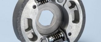
There is a worm in the power steering housing, which is additionally tied with turns. A spool is installed on the end part. The ends of the part are provided with bearings to support the structure. During operation of the unit, plungers rest against the bearings, creating pressure. In turn, on the other side, the springs rest against the housing, the parts of which are also part of the design of the amplifier.
Due to the work of the springs, it is possible to fix the position of the spool, preventing it from moving in different directions. When the tractor driver begins to rotate the wheels, making a maneuver, the sector of the assembly moves under the influence of a worm, which rotates in turns. As a result, the bipod shaft rotates.
During rotation, resistance arises in the wheels, which is absorbed by the worm. This rotation creates a certain force, under the influence of which the worm moves forward or backward along one axis, depending on what maneuver the driver performs.
During the movement of the worm, the spool of the force distributor of the unit is activated simultaneously with it, which also begins to move along the axis. The movement of the spool affects the oil flow, distributing its supply into the cavities.
If the car is moving straight, the spool is in the neutral position, supported by the springs. Pressure enters the power steering housing, which is also the hydraulic tank of the unit system.
When the steering wheel rotates, the force applied to the hydraulic booster causes the worm to move, which, in turn, changes the position of the spool. With the help of the belts provided on the spool, the lines of the cavities inside the cylinder are opened. Depending on which direction the turn was made, one receives oil, and the second becomes a drain for liquid.
Pressure inside the cavity with oil is supplied by the spool only when the steering wheel begins to rotate. As soon as the wheel stops, the worm stops moving, and along with it the spool brakes, which with the help of springs returns to its original position. The oil is discharged into the cavity, which is responsible for draining.
Additional items
The design of the unit includes a piston, which acts on the rack during movement. The piston is connected to one of the sectors of the hydraulic booster and is responsible for pumping pressure inside the cylinder. When pressure is supplied to one of the cavities due to the operation of the spool, force is simultaneously transferred to the rack, which begins to move the sector.
The standard pressure in the hydraulic system is 2-4 MPa. If the tractor owner decides to turn the steering wheel to the maximum, the pressure can rise to 8 MPa.
Operating principle of the device
The power steering, the adjustment of which must be carried out in accordance with the established maintenance periods, is connected to the hydraulic booster housing and the power cylinder, as well as the pump mounted in the engine housing via an oil distributor. The drain line is equipped with a special filter, complemented by a pressure-reducing valve. The system cannot be activated if the resistance when turning the wheels is insignificant. A worm is responsible for transmitting the force coming to the bipod from the steering wheel, sending it through the rotary shaft. The force that the bipod receives is an order of magnitude less than that required to move the distribution valve and simultaneously compress three springs. If the spool takes a neutral position, the oil coming from the pump goes to the housing drain through the existing distributor. If the resistance when turning is very significant, the spool changes its position relative to the neutral position, while one of the cavities of the hydraulic booster cylinder is connected to the drain, and the second to the pump oil line. When oil pressure is applied to the rack, the sector, together with the bipod and the shaft, rotates, and the springs ensure that the spool is held in a neutral position. Excess pressure is released via a safety valve.
Possible breakdowns
The products of the Minsk Tractor Plant are of high quality, as well as excellent technical characteristics. However, despite the long service life declared by the manufacturer, during operation of the tractor it may be necessary to repair the power steering and make a number of adjustments to the steering control unit.
Among the most common malfunctions and breakdowns:
- tight steering control;
- inability to turn the tractor steering wheel;
- the occurrence of delays in the operation of the control unit.
To fix the problem yourself, it is worth disassembling the unit and troubleshooting and adjusting individual elements, as well as replacing broken parts if necessary. After repair work, it is necessary to return the steering assembly to its place and check the quality of the repair.
Unit repair
There are several possible scenarios for repairing the power steering unit. They depend on the type of breakdown or malfunction that occurs.
Oil leak and depressurization
The first criterion demonstrating the presence of a malfunction in the unit is the lack of tightness of the hydraulic system seals. The tightness ensures the safety of the operating pressure during operation of the unit, and also prevents changes in the magnitude of the force that acts on the amplifier organs.
If an oil leak is detected in the power steering, the following is replaced:
- oil seals;
- rings;
- gaskets that are provided with the amplifier kit.
The proper functioning of the connection of the assembly parts ensures the normal operation of the structure, preventing jamming or breakage.
Changing the working stroke
The standard spool stroke, if we consider the classic movement of the part in one direction, is 1.2 mm. This is enough to completely open the channels for the inlet and outlet of working fluid. If the stroke is disrupted and the structure deviates in any direction, the distributor ceases to cope with its function.
The result of the malfunction is the lack of a sufficient amount of working fluid in the cavity, which makes it impossible to create the required amount of hydraulic gain.
One of the reasons for such a malfunction is unacceptable backlash that occurs when assembly units are connected poorly. In total, these backlashes negatively affect the movement of the spool along the axis. Therefore, it is important to keep track of:
- The state of fastening of parts to each other.
- The size of the gaps formed in the gears.
If the backlash is adjusted incorrectly and the indicators are allowed to change, the design of the unit will quickly wear out, which will lead to breakage of the teeth, coils, and worm. If parts fail, they should be replaced with new elements.
Increasing the distance between parts
During operation, gaps between individual elements that do not require tightness may increase. Tractor drivers recommend using two methods for leveling the resulting gaps:
- Increasing the dimensions of the spool along one axis. To do this, the element is machined and special bushings-washers of suitable width are additionally machined. The diameter of the washers must correspond to the diameter of the spool recess on the inside. The improved part is installed in the assembly structure; gaskets have previously been placed to organize a sealed connection. It is noteworthy that it is precisely due to the gaskets that it is possible to compensate for the increased dimensions of the spool. To increase the rigidity of the springs holding the part, additional washers are machined, taking care of a diameter of 1.5 mm in advance, and mounted between the spool and the plungers.
- Grinding the cover fastening in order to improve its fastening to the power steering housing. In this case, it is also necessary to take care of the diameter, which will be 4 mm larger than the diameter provided for the thrust bearing race. The advantage of this method is that there is no need to install gaskets to ensure tight connections. There is also no need to cut washers for the springs.
Both methods are in demand in practice, but they are not capable of completely repairing the unit if they are installed incorrectly and all conditions for their reliable operation are not provided. If incorrectly adjusted, enlarged elements will quickly wear out and lead to power steering failure.
Malfunctions and repairs
The first criterion affecting the efficiency of the unit is the tightness of all seals of the hydraulic system, which maintain the working pressure of the fluid, providing force on the working parts. Elimination of oil leaks and pressure loss is achieved by replacing all rubber seals, O-rings and gaskets included in the complete power steering repair kit.
The serviceability of the joints of the mechanical drive, the adjustment of the engagements of the worm gearbox and the piston rack with the sector ensure the operation of the mechanism without jamming.
The reason for a tight steering wheel, if the system is well sealed and the oil level is sufficient, may be poor compression of the power piston of the amplifier cylinder or insufficient stroke of the distributor spool, which does not allow opening the discharge line to the cylinder cavities.
Replacing the compression rings on the piston and the sealing ring on the rod eliminates the flow of oil from the injection cavity into the drain, increasing the efficiency of the cylinder and, accordingly, the generated useful force.
With proper adjustment and in good condition, for the spool to fully open the channels, the working stroke in one direction should be 1.2 mm. If the stroke is disrupted, the distributor does not perform its function, which leads to incomplete opening of the discharge channel to supply pressure to the cylinder cavity and sufficient hydraulic gain is not created. Often the cause is unacceptable play in the connections of the amplifier assembly units, which in their total negatively affect the provision of the required parameters for the movement of the spool. Therefore, it must be said that the success of the distributor depends on the technical condition of the connections of the parts and the compliance of the gaps in the gears.
It is technically sound and correct to replace the failed parts in case of unacceptable backlash or impossibility of adjustment as a result of wear of the contact working surfaces of teeth, worm turns, bushings, and bearings.
Many tractor drivers use in practice a technique that temporarily levels the gaps when power steering parts wear out and affect the operation of the distributor. The normal working stroke of the spool is achieved in two ways:
- The linear size of the spool is increased by grooving on both sides of the internal diameter of the part with a width of 4 mm and a body depth of 1 mm. Sleeve-washers are machined with the appropriate width and diameter to fit into the inner diameter of the spool recess and the protruding part with a width of 1.2 -1.5 mm with the corresponding outer diameter. The upgraded part is installed by placing additional gaskets between the column body and the distributor and the distributor cap. In this way, the increased size of the spool is compensated. To increase the rigidity of the plunger springs, additional washers of the appropriate diameter with a thickness of 1.5 mm are machined and installed between the spring and the part.
- The second method is simpler - grind the cover mounting surface on the distributor body. The diameter of the groove from the center of the hole for installing the spool and the worm axis is made 4 mm larger than the diameter of the thrust bearing race with a depth of 2-2.4 mm. In this case, there is no need to install additional gaskets between the bodies and covers, as well as install washers under the plungers.
The described technique takes place in practice, however, it does not solve the problem of the general technical condition of the unit. Increased gaps in the joints as a result of wear or improper adjustment will still lead to a complete failure of the unit to perform its function. Therefore, before resorting to this method, try to determine the cause of insufficient spool travel and eliminate it by replacing worn parts with subsequent adjustment, according to the manufacturer’s operating recommendations.
Adjustment
You can configure a node only if all its elements are in working order. The correct setting is determined by the factor in the form of reliable and safe operation of the amplifier while driving the tractor. The setup is carried out in several stages, and each of them is worth considering in detail.
Worm adjustment
Before making adjustments, it is necessary to check the serviceability of the steering rods and the reliability of the steering drive fastening. You should also check the free play of the steering wheel, which should not be more than 30 degrees if the engine is running. If malfunctions are found, it is necessary to eliminate them and only then resort to adjustment.
- First, use a jack to raise the front axle, and also dismantle the bipod, disconnecting it from the steering rods.
- Then loosen the bolt, which is responsible for the eccentricity of the sleeve.
- Twist the sleeve until it stops, ensuring maximum adhesion of the worm to the sector.
- Rotate the steering wheel to determine the engagement rate. This must be done with the engine running. Additionally, at this time, increase the clearance by continuing to rotate the bushing counterclockwise.
The final step is to tighten the bolt that secures the bushing to the assembly structure. Afterwards all that remains is to remove the tractor axle from the jack and connect the bipod to the steering rods.
Adjusting the worm nut
By turning the worm nut, it is possible to level the gap that occurs between two elements: the cages and the spool. The gap appears due to power steering exhaustion or weakening of the fastening element. The larger the gap, the worse the free steering control, and in the end such a malfunction can lead to breakdown of the unit.
The adjustment occurs as follows:
- First, dismantle the assembly housing cover by unscrewing the bolts.
- Next, the distributor is secured using two bolts, which must be positioned diagonally on the housing. In this case, the thickness of the cover flange is restored using backings made of washers or nuts.
- The third step is to tighten the adjusting nut. It will be pinned until the spool rests against the races provided in the bearings.
- Then turn the spherical nut of the structure until it coincides with the hole that is located on the shaft. When this happens, the nut is tightened.
- Remove the installation bolts, which were secured with washers, and return the cover to its place, additionally providing for replacing the gasket.
- The four cover mounting bolts are screwed back in.
With the help of proper tightening, it is possible to ensure a tight fit of the spool to the surface of the races provided in the bearings. Thus, the element returns to the neutral position when turning is stopped, and the gap between the parts disappears. It is worth noting that it is not recommended to overtighten structural elements, as this may lead to wear.
Adjusting the spool stroke
To adjust the spool stroke, it is necessary to use gaskets that are installed between:
- Distributor and amplifier housing.
- The distributor and the surface of the spherical nut cover.
If turning to the left requires additional effort from the tractor driver, then you will need to install another gasket, the thickness of which should be in the range from 0.5 to 1 mm. It is mounted in the space between the column and the distributor. In cases where it is not possible to ensure normal rotation to the right, a gasket is installed under the nut cover in the shape of a sphere. Due to this adjustment, it is possible to align the movement of the part.
When the adjustment is completed, you will need to check the pressure in the system and tighten a number of nuts and springs if the pressure indicator is not enough. Operation of the MTZ-80 requires a responsible approach and regular diagnostics of the power steering unit.
Wheels do not turn on MTZ 82 power steering adjustment
Questions can only be asked after registration. Please login or register.
Tell me about the hydraulics of the steering wheel, what is there and how to adjust it on the MTZ 82. The problem is turning the steering wheel, it doesn’t turn to the right at all, but only half to the left. free play 1.5 turns at the steering wheel. and when I turn left, the wheels turn a little later than the steering wheel.
Something specifically fell apart for you. Remove the top cover, look at the nut on the bipod, below, check the play on the splines, it shouldn’t be loose! Also check the sector from above, look at the sector-worm gearing.
I've already done it all. The nut is in place, the splines are not loose, the worm sector engagement is loose, but not critical. I can’t quite figure out how this system works and why the steering wheel won’t turn.
I had this happen, I didn’t turn it in one direction, the thrust bearing was broken, in the power steering distributor, in front you need to remove the cover with 4 bolts
The bearings are all intact, the engagement is normal with both the worm and the cylinder. there are no backlashes. What is the lock sensor and what function does it perform? could that be the problem?
If everything is fine, then check how the steering knuckles, that is, the final drives. If 82, they turn.
Now I took everything apart, cleaned it, put it back together, the situation has changed, it turns out that it spins almost two turns in one direction, and about 0.8 turns in the other. and the problem with the lag remains. You turn the steering wheel, the wheels a little later. I haven’t tried it on the go though. How many turns of the steering wheel should there be in each direction?
Steering hydraulic cylinder device
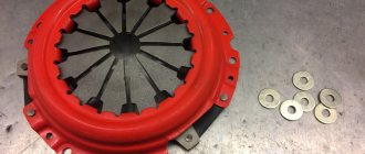
The unit consists of a cylinder body, a rod, a piston, a cover, and a union nut. The piston is secured to the rod with a nut, fixed by core into the grooves of the rod. The piston is equipped with a combined seal that eliminates friction between the metal surfaces of the piston and the cylinder. The housing cover contains a wiper cuff, guides and rod cuffs that prevent friction of the parts. The housing and rod lugs are equipped with spherical plain bearings with channels on the inner ring for lubricant to flow to the rubbing surfaces through grease nipples in the connecting pins.
The device of the MTZ steering hydraulic cylinder
Among the mass of hydraulic cylinders produced and offered on the market, an indicator of good quality is the wear resistance of the metal and its corresponding processing. And also resistance to wear and stress of the unit seals. Thus, one of the first signs of the quality level of the unit is a perfectly processed, honed (polished) smooth surface of the rod, which ensures minimal friction and maintains the tightness of the seals in the hydraulic cylinder cover during operating cycles.