Launcher Magneto
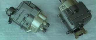
The PD 10 starting engine uses a right-handed M124-B1 magneto with a constant spark formation moment (ignition timing is 27º). The magneto is driven using a rigid coupling half from the starting motor drive gear.
The magneto body is made of zinc-based alloy. The rotor, which is the main part of the alternating current generator and is designed to generate and change the magnitude of the magnetic flux that passes through the core, is mounted on two ball bearings between the pole shoes of the magnetic circuit. The rotor structure includes two rollers and a package of lamellas pressed onto a magnet. The magnet with lamellas and rollers are filled with zinc alloy.
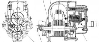
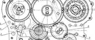
Magneto launcher PD 10: 1 - housing; 2 - rotor; 3 — magneto cover; 4 - transformer; 5 - high voltage output; 6 — breaker cover; 7 - cam; 8 - capacitor; 9 - half coupling; 10 — breaker lever; 11 — contact stand; 12 — remote shutdown terminal; 13 — shutdown button; 14 - felt.
Magneto transformer
The transformer is designed to create high voltage current. Its main component is the core, consisting of separate plates of electrical steel, primary and secondary windings. The end parts of the windings are protected by getinax cheeks. One of the cheeks of the transformer is equipped with a tip to which the end of the primary and the beginning of the secondary winding are soldered. The tip is connected to the contact post of the breaker. The end of the secondary winding is soldered to the electrode through a protective tape. The secondary winding consists of a large number of turns of thin wire, and the primary winding consists of a small number of turns of thick wire. To improve the electrical strength, the transformer is impregnated with turbine oil.
The breaker connects a cam located on the rotor shaft with a contact post and a lever with tungsten contacts. These elements, together with a filter for lubrication of the cam, are located in the magneto cover. When the magneto rotor rotates, the cam breaks the contacts of the breaker, thereby forming a gap of 0.25-0.35 mm.
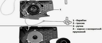
Light from a magneto on an ant scooter. The best videos
My father's idea took more than 3 months to assemble. Later I will post a video with a detailed description, the previous account was lost
It was necessary to dissolve the 50 mm board into bars, the Interskol 1600 parquet floor the day before on these boards the armature and stator windings smoked, it needed to be changed, so we had to return to the old grandfather’s method. Wings, legs... it’s better to lose half a day, then fly in 5 minutes. Well, regarding the magneto, it was a temporary solution and probably very correct.
8 months ago
Magneto operating principle
During rotation of the rotor, a magnetic flux of varying direction and magnitude is formed in the transformer core and the magnetic circuit of the housing, crossing the turns of the primary winding of the transformer and creating an electromotive force in it. Under the influence of this force, a low-voltage alternating electric current is created in this winding.
When the current reaches its maximum value, the breaker is triggered, breaking the current in the primary winding. The electric current in the windings instantly disappears, the magnetic flux quickly decreases and simultaneously forms a high-voltage electromotive force in the secondary winding, under the influence of which a spark discharge is created between the electrodes of the spark plug, which is necessary to ignite the working mixture in the starter cylinder PD 10.
To reduce burning of the breaker contacts when they open, a capacitor is connected in parallel to them. To protect the transformer from breakdown when the high voltage wire breaks or is disconnected, the magneto has a spark gap between the magneto body and the high voltage electrode.
The magneto is turned off remotely using the VK322 switch, located in the cockpit on the starting motor control panel. The magneto can also be turned off using a button installed in the magneto housing.
A blocking device is mounted on the MTZ 82 tractor to block the start of the starting engine when the gear is engaged. This device blocks the magneto, shorting the transformer winding to ground. There is a VK403 switch on the gearbox cover. If the gear shift lever is in the neutral position, its contacts are open. When the gear is engaged, its contacts close, connecting the primary winding of the transformer to ground, blocking the formation of a spark and, accordingly, the start of the PD 10 engine.
Walk-behind tractor ignition device
The ignition system is one of the most important components of both branded and homemade walk-behind tractors. Its main function is to generate a spark, which is needed for ignition and gradual combustion of fuel in the chrome-plated cylinder of the internal combustion engine.
The simplicity of the factory design of the unit allows you to perform your own repair of the ignition of a walk-behind tractor, which, most often, involves setting a gap between its elements. However, to do this correctly, you need to study the design of the unit.
The ignition device of any household agricultural unit includes a coil, which is initially connected to the electrical power supply of the system, as well as a magneto and spark plugs. When starting the power unit of the walk-behind tractor, voltage is supplied, as a result of which a pronounced spark is formed between the magnetic “shoe” and the standard spark plug. It is necessary for instant ignition of the fuel, which at this moment is in the combustion chamber of the engine. The photo will tell you more about the structure of the ignition system of the walk-behind tractor used.
The electronic ignition system of a walk-behind tractor is also often equipped with breakers that are triggered automatically when any unit malfunction occurs. This leads to an emergency shutdown of electrical power in the network.
Magneto maintenance and repair
Magneto maintenance consists of periodically monitoring cleanliness, secure fastening, the need for lubrication, cleaning the contacts and adjusting the gap between the breaker contacts. Every 960 hours of tractor operation, check the condition of the breaker contacts and the gap between them.
When carbon deposits are detected, the contacts are cleaned using a special file that does not leave abrasive dust. Before starting stripping, increase the gap between the contacts to allow free passage of the file. Each contact is cleaned separately, after which it is necessary to adjust the gap between the magneto contacts and wipe them with a rag soaked in alcohol or gasoline.
After 1440 hours of operation, it is necessary to check the presence of grease on the face of the cam using tissue paper or similar paper according to the degree of its lubrication. If necessary, soak the filter with 3-5 drops of turbine oil. Excessive lubrication of the cam fillet is not recommended, since it is not permissible to apply oil to the contacts.
Adjusting the gap between the breaker contacts
Using a special probe, the gap between the contacts of the breaker is checked, while turning the crankshaft of the starter by the flywheel until the maximum divergence of the contacts occurs. To adjust the gap, you need to loosen the screw securing the contact post and turn the post of holes inserted into the eccentric slot.
Every two years of operation, it is recommended to change the grease in the magneto bearings, for which you first need to disassemble the magneto and remove any remaining old grease. Afterwards, rinse the bearing separators in gasoline and wipe them and the outer rings dry with a clean rag.
After assembly, the magneto must be tested on a bench. The following option for checking the magneto is also allowed. Connect the high-voltage wire to the high-voltage output and holding the other end of the wire at a distance of 5-7 millimeters from the magneto body, sharply turn the rotor to the right, while the correctly assembled and adjusted magneto should form a spark discharge.
Diagnostics of technical condition
Diagnostics is carried out by performing the following procedure:
- The first stage is connecting the high-voltage cable to the voltage terminal.
- The second end of the cable is constantly held at a distance of about 0.5-0.7 centimeters from the device body.
- Maintaining position near the wire. Next comes a sharp turn of the rotor in the direction of rotation. The spark should jump as a result of this movement; if everything is in order, the magneto is adjusted correctly. If there is no spark or is too weak, there is a high probability that the installation requires a malfunction check. If necessary, adjustments are made.
Common malfunctions and their repairs
Here are just a few of the most common problems magneto owners may encounter:
- Failures during sparking. There are several reasons for this situation and ways to resolve the problem. Possible problems include: contacts burn, oxidize; the gap adjustment is violated; the lever cushion at the breaker is worn out; The capacitor element was broken. If an element fails, it is completely replaced. When the problem is in the gaps, they undergo additional adjustment. Contacts are also changed or completely cleaned. How to set up the magneto is described further.
- Complete lack of spark. This often happens because the transformer wiring has broken, there has been a short to ground, or the insulating layer that supplies the high-voltage cable has broken through. If problems arise with the transformer, the unit must be replaced. You can eliminate the short circuit itself or change the cable when an insulation breakdown occurs.
- A broken capacitor is the most likely cause of a spark that is too weak. In this case, the part must also be replaced.
Candle and armored wire
It is recommended to abandon the caps used for armored wires. It is better to use an alligator clip.
The armored wire itself also requires additional testing. This concerns two elements:
- Fastening in the mounting socket.
- Base for a candle.
Complete stripping of the wire from each end by 2 millimeters is an excellent reason for inspection and repair. You can check using a different armor wire instead of the one installed initially. If the spark plug is faulty, it is also replaced; the part is not repaired.
Part diagram
Capacitor
It is needed so that the contacts do not burn too much. It consists of two plates and insulation, the role of which is usually played by foil. Everything is rolled into one roll and placed inside the case. In some cases, if the housing is damaged, the capacitors can be adjusted using sandpaper. It is important that the structural parts do not overheat during operation. Adjusting the magneto after this will not help.
Be sure to read: Steering MTZ 82
Sometimes it is recommended to install two capacitors at once, then the operation of the mechanisms will be more reliable and stable.
About breaker contacts
If they become faulty, the first recommendation is to clean the surface using a special flat abrasive plate. The work can be done without problems with a flat file with a fine notch. Cleaning with sandpaper or glass paper will not give the desired result. The contacts wear out too quickly, and in this case a flat surface cannot be obtained.
From time to time, contacts also require cleaning from plaque and adjusting the gaps between parts . The main thing is not to lose a single part during disassembly. The contact spring is subject to malfunction or straightened in the opposite direction.
Coil or transformer
It is easy to repair the tractor magneto for such parts. This same part of the engine rarely fails; it can operate uninterruptedly for a long time. If the part has become unusable, then it must be replaced with exactly the same, but working model.
Rotor
The main thing is that it does not crumble or break during operation. From time to time the rotor can become demagnetized. If the part really turns out to be damaged, then it is replaced. The main thing is not to forget to remove metal fragments, sometimes they remain inside the magneto housing. Bearings require separate inspection and lubrication.
Installing the ignition on the PD 10 starter. How to install a magneto on the starter
The ignition timing is set at the factory and does not need adjustment during operation. However, if the magneto was removed from the starting motor or replaced, then the following steps must be followed to install it correctly:
1. disconnect the wire from the spark plug and unscrew it; 2. Lower the rod into the hole for the spark plug and, using it, turning the engine crankshaft clockwise, determine the moment the piston reaches top dead center; 3. Turn the crankshaft in the opposite direction and set the piston 5-6 mm below the top dead center; 4. remove the breaker cover, rotate the roller and find the position corresponding to the beginning of the breaker contacts opening; 5. insert the protrusions of the coupling half into the grooves of the drive gear and secure the magneto with bolts; 6. Install the breaker cover and connect the wire to the spark plug.
Ignition control algorithm
The ignition on the trimmer is adjusted quite simply.
- Remove the casing from the engine by unscrewing all the bolts holding it in place. For example, on the Patriot PT 2540 lawn mower, to remove the casing, you will need to unscrew the air filter housing and use a flat screwdriver to remove it from the latches. After this, the plastic case can be easily removed.
- Using a screwdriver, unscrew the 2 bolts (no need to completely unscrew) holding the magneto.
- Turn the flywheel so that the magnets are at the top.
- Next, in order to correctly set the best gap between the flywheel and the coil, you can use a regular business card or pocket calendar. If you don’t have either one or the other on hand, then to set the ignition, you can use a sheet of A4 paper, folding it 2 times (in the end, you will get 4 sheets thick). This thickness will be enough to obtain the optimal clearance and adjust the ignition. Insert a business card or paper between the spool and the magnets.
- The magnetic field will attract the coil to the flywheel. Hold the magneto in this position with your fingers and tighten the bolts holding it in place.
- Remove the business card. After this, the ignition on the trimmer will be adjusted.