"Europeans" and "Americans"
First crawler
Austrian hydraulic crane manufacturer PALFINGER has launched its first crawler crane. The PALFINGER Crawler Crane PCC was first presented to the general public in September 2022. Initially, the line included three models with a load moment from 50 to 150 tm. The purpose of such a machine is to work in hard-to-reach areas, where a crane on a vehicle chassis would get stuck and would not be able to work.
The new machine is designed on a modular basis and consists of three components: a tracked undercarriage, a crane unit and a counterweight.
The PCC crawler crane is 400mm narrower than a standard truck and is said to be capable of working on slopes of up to 60%. The crane boom is articulated (or cranked), folding, like all booms of PALFINGER cranes. Thanks to this, places where work space is limited, industrial premises are another potential area for use of these new series cranes. One of the main advantages of this type of crane is that it can be easily and quickly moved to a new location on a construction site.
The manufacturer states that the crawler undercarriage and crane unit can be controlled, transported and operated separately from each other. This is convenient in situations where there are restrictions on the weight of the crane. The crane rig can use its outriggers for movement when working separately from the crawler undercarriage; PALFINGER experts call this method of movement shifting. It is also possible to install the crane unit on a transport truck. The PCC installation requires a minimum space width of 2 m and a moving height of 2.2 m. In addition, to move around construction sites in places where there is not enough space, the crane installation can use shifting (the crane moves only with the help of its outriggers). The crane installation can be delivered to the construction site in a container. On uneven surfaces, by moving the outriggers vertically, you can install the crane evenly on a site with a slope of up to 20°.
PALFINGER offers three versions of the crane system: PCC 57.002 with a maximum reach of 29.5 m, a maximum lifting height of 32 m and a lifting capacity of 17.9 t. Mod. PCC 71.002 with a reach of 31.6 m, a lift height of 34 m and a lifting capacity of 19.1 t. The largest of the three modes. The PCC 115.002 has a reach of 33.3 m, a lift height of 35.8 m and a lifting capacity of 30 t. The two larger models are already on sale, and the PCC 57.002 will hit the market in the second quarter of 2019.
Each new one is more perfect than the previous one
Using the HC 110 crawler crane as a basis, Terex developed a new mod. HC 120 lift capacity 109 t, with a boom length of 70.1 m and a maximum boom length with extensions of 86.6 m, with a 250 hp engine. (185 kW). Boom extensions are also available - fixed and tiltable, which can be installed together. The width of the track shoes is 914 mm. The vehicle speed is 0.96 and 1.5 km/h. The crane is capable of working on slopes up to 17°.
The two-speed winch allows the operator to select the optimal speed and power for any working condition. There is a system for damping speed and shocks at the end of lifting and lowering the load and boom.
Compared to the previous model, transportation mod. HC 120 is cheaper, easier to prepare for work, and cheaper to operate. The crane is equipped with a newly designed 0.94 m wide cabin with improved sound insulation and visibility through curved floor-to-ceiling windows. The cabin has air conditioning, an adjustable seat, winch rotation indicators, an interactive screen with a load moment indicator, the operator can set various forms of data on the screen. The operating temperature range of the hydraulic system components is from –20 to +95 °C. The hydraulic system for removing the counterweight (consists of 5 weights) allows you to do without fastening bolts, simplifies and speeds up the process of installing/removing the counterweight. The counterweight is located lower than the previous model. The electronic control system of the HC 120 has also been improved; the load moment and level position of the machine are automatically controlled. The machine is convenient for transportation: overall width – 3.66 m, overall height – 3.28 m.
High Capacity Crawler Crane
Liebherr, headquartered in Switzerland, has launched a new crawler crane mod. LR 1800-1.0 lifting capacity 800 t. As stated, the new crane was developed as a machine capable of providing high lifting capacity at low transportation costs. The crane is equipped with a jib with variable reach and a derrick system, which makes it possible to use it in industry. The LR 1800 is currently the most powerful crawler crane on the world market with a crawler chassis width of no more than 3 m.
In the model name, the company introduced a new index for crawler cranes: a number with a hyphen “-1”, which means “the first model of an 800-ton crawler crane.” The number “0” at the very end after the dot means the first version. After major technical upgrades, 0 will change to 1, 2, etc. to designate future versions. The basic machine has an overall width of 3 m. According to Liebherr experts, the increased height of the structure ensures the rigidity of the crane. A Quick Connection system, which allows the top of the turntable to be removed to save transport costs, is included as standard.
The boom system consists of three lattice sections, which are nested one inside the other during transportation. In the standard configuration, the main boom and jib are each 84 m long. At the bottom of the main boom there are lattice sections (large). Medium lattice sections make up the top of the main boom and the bottom of the jib, while small lattice sections make up the top of the jib. The standard boom length can be increased to 102 m plus an additional 102 m jib.
The crane is equipped with the Liebherr VarioTray system. Thanks to this system, after lifting the lattice boom with derrick ballast, part of the ballast plates can be easily and quickly removed by simply removing the fastening pins. In most cases, lifting operations at near-vertical boom positions require only a small portion of ballast weights. In this way, the VarioTray system makes the labor-intensive installation and removal of ballast weights easier and simpler.
For suspended ballast, the LR 1800-1.0 uses a new type of guide: a hydraulically adjustable tilting frame allows the ballast radius to be adjusted up to 23 m. This means that a fixed rigid guide is no longer needed for larger radii. Ballast weights are standard, as on other Liebherr cranes, 10 tons. The LR 1800-1.0 crane operates with a maximum slewing platform ballast of 230 t, a central ballast of 70 t and a derrick ballast of up to 400 t.
With the tracks removed, the crane's transport weight is less than 45 tonnes. As standard, the track shoes are 2 m wide to keep the ground pressure as low as possible.
The crawler undercarriage is equipped as standard with four drive mechanisms. The crane is equipped with a Liebherr V8 diesel engine with a power of 455 kW of environmental class Stage V, and is also equipped with an electronic control system Liebherr Liccon 2, which controls the safety of deployment into the working position and the equilibrium position of the crane.
Skillful Japanese
Production has already started
Japan's Kobelco Construction Machinery introduced the new hydraulic crawler crane CK3300G-2 (North American model), CKE3000G (European model) and CKS3000 (standard model) in early 2022, which are the largest models of Kobelco CK/ CKE/ CKS series multi-purpose crawler crane. The cranes are fully in production. At mod. CK 3300G-2 lift capacity is 300 t, and the modification with the SHL (Super Heavy Lift) lift lift capacity is 350 tonnes. The boom length is 90 m, and with an unguided jib – a boom of 78 m plus a jib of 30.5 m. With reinforced unsteered jib: boom 72 m plus jib 29.9 m. Lifting capacity with a steerable jib is 120 t, maximum length of a steerable jib is 66 m, maximum length of a lifting boom to a steerable jib is 60 m.
A drum winch with free rotation of the drum when lowering the projectile (free fall winch) is available as an option. “The SHL crane can compete with cranes of the 400–500 t lifting class,” the company claims. The overall width of the crane in transport position is less than 3 m. The cross-country ability of the chassis has also been improved by increasing ground clearance.
All models are equipped with tilting cabs with increased glass area. An intuitive load moment limiter with clear icons allows the operator to quickly assess lifting capability and is controlled via the touch screen. The system ensures that lifting is always carried out within the workload diagram increases safety. For transportation, the crane can be stacked on 17 trailers - in order not to exceed the load and weight of the vehicle permitted by local regulations. The nominal weight of the crane is 107.5 tons. It can be equipped with a self-assembly system for tracks, the lower part of the boom system and counterweights.
Since 2003, Kobelco Construction Machinery has supplied Manitowoc with lattice boom crawler cranes up to 150t, which have been sold in North America and Europe under the Manitowoc brand through the Manitowoc distribution network, and short-wheelbase Grove cranes in Japan have been sold by Kobelco. In November 2022, Kobelco and Manitowoc announced they would terminate the agreement. After 15 years of such cooperation, the companies agreed to further develop their lines of crawler cranes, each in their own way. Kobelco states that the termination of this agreement will have no impact on owners of Kobelco crawler cranes or future customers of the brand's cranes. Owners of Manitowoc cranes manufactured by Kobelco will continue to receive service support from Manitowoc dealers.
Third model in the series
In early 2022, Japanese crane manufacturer Sumitomo Heavy Industries Construction Cranes Co. (HSC) (former name: Hitachi Sumitomo Heavy Industries Construction Crane Company ) released hydraulic crawler crane mod. SCX800E capacity 80 t. This is the third model of the SCX E series (the other two are SCX550E and SCX700E). The boom length is 54.5 m, the turning radius is 3.2 m. The jib length is 9–18 m. The maximum boom length with jib is 45.5 +18 m. Engine power is 140 kW. The developers paid serious attention to ensuring operational safety: in addition to the usual lift limiter (locking in the event of the traveling suspension blocks approaching each other), the standard equipment includes an automatic blocking device for the boom lift winch. An automatic boom lift winch drum lock is also installed, which locks and releases the drum depending on the operation being performed, which helps prevent unexpected accidents.
The extra-wide (1040 mm) air-conditioned cab provides the operator with comfortable working conditions and excellent visibility. Hydraulic filters, relays and electrical fuses are grouped and easily accessible for easy maintenance. The machine with an operating weight of 80 tons is capable of working on slopes of up to 17°. The crane can be equipped with a grab. The speed of the crane is 1.3 km/h.
The model is intended for the markets of Asia, Africa and the Middle East.
MAIN UNITS AND MECHANISMS OF CRAWLER CRANES
Crawler cranes are used for loading and unloading, construction and installation work and are widely used in energy construction, both when working at large-scale assembly sites and when installing equipment. The advantage of crawler cranes is that they do not require special preparation of the working site due to the low specific pressure on the ground, they have sufficient maneuverability, and can turn on the spot with or without a load. When installing equipment, they can bring the mounted block into a vertical position and then move it to the design mark.
Crawler cranes are self-propelled jib cranes. Depending on operating conditions, cranes are equipped with replaceable booms of various lengths and configurations (straight, curved, telescopic).
According to their design features, crawler cranes are divided into two groups:
1. Jib self-propelled cranes.
Indices: “DEK”, “SKG”, “MKG”, “MKGS”, “RDK”. Assembly crawler cranes have a lifting capacity of 40-160 tons or more (for example, MKGS-250 and MKT-250 cranes). The drive of the individual mechanisms of these cranes is, as a rule, individual.
2. Mechanically driven excavator cranes, manufactured on the basis of excavator units. Excavator cranes have a small lifting capacity (no more than 50 tons) and a group drive mechanism.
Cranes of the "SKG" type with a lifting capacity of 24, 40, 63, 100 tons are produced with various types of boom equipment:
— tubular arrows with short jib;
- tower arrows with long jib.
A crawler crane consists of two main parts: a slewing and a fixed crane.
Rotating part
The principle of the rotating part is similar to the design of wheeled cranes.
Fixed part
It is a running welded frame connected to two longitudinal beams on which final drives are installed. The crane is turned by slowing down one of the tracks, while the speed of the second one increases. When one track is fully braked, the speed of the second doubles, and the crane rotates around its axis.
The movement mechanisms are made with separate drives of crawler bogies according to several design schemes. The lifting mechanisms have a dual-motor drive with a differential, which gives four speeds.
Appendix No. 54
ORGANIZATION OF LOADING AND UNLOADING WORKS
CRANES IN TIMBER YARDS
The storage area for timber must be leveled, the soil compacted, drainage of surface water ensured, and for each stack there must be a stacking base made of support logs with a height of at least 15 cm for wet storage and at least 25 cm for dry storage.
On soft soils, a continuous flooring of low-grade logs should be made under the support logs.
Timber to be stored in warehouses must be sorted by assortment (wood species and sizes).
At the timber warehouse, measures must be taken to protect timber from mechanical damage and cracking, infection by fungi and insects, and excessive moisture. At least once a month, timber must be inspected by the person responsible for storage.
Round timber in a timber warehouse should be stacked in rows, cages or bundles (Fig. 2).
Stacking and dismantling of dense stacks can be done by cranes with grabs, loaders with jaw and manipulator grips, winches equipped with self-release slings, log grabbers and other devices that ensure safety during work.
Rice. 2. Laying round timber:
a) - ordinary stack
b) - cell stack
c) - pack stack
The upper ends of round timber arriving at the warehouse must be marked with symbols.
Rising and lowering from stacks and packages when stacking and disassembling them should be done along the inclined surface of the head or tail of the stack (package) or along an extension ladder.
The height of a stack of round timber should be no more than 1/4 of its length and should not exceed one and a half times the length of the logs stacked.
The height of the stack should be no more than: 1.8 m for manual stacking, 3 m for stacking with a jaw loader, 6 m for a cable crane, 12 m for bridge, tower, portal and gantry cranes. The formation and dismantling of stacks with a height of 7 m or more must be carried out using grabs.
When laying stacks of round timber, the following requirements must be observed:
1. The intervals between individual groups of stacks must comply with fire safety standards for the design of timber warehouses;
2. Individual logs should not protrude beyond the stack by more than 0.5 m;
3. Spacers must be laid symmetrically to the longitudinal axis of the stack at a distance from the ends of the logs no more than 1 m on each side;
4. Inter-row spacers along the height of the stack must be laid in the same vertical plane;
5. Gaskets along the stack must be laid in one line, and their ends at the joints must overlap by a length of at least 1 m;
6. It is allowed to stack round timber in one stack, differing in length by no more than 1 m for coniferous trees and no more than 0.5 m for deciduous trees;
7. The ends of the row stack must have a slope, for which each new row must be shorter than the previous one by the diameter of the log on each side. The outermost logs of each row should be placed in nests cut out at the ends of the spacers with a depth of no more than half the thickness of the spacers;
8. At the end of dense, close-row and stacked stacks there must be devices that prevent arbitrary rolling out of logs. In the absence of such devices, the ends of the stacks should have an angle equal to the angle of natural rolling of the logs (no more than 35°).
In rail warehouses, round timber of the same length must be stacked in one stack.
In riverside warehouses for moth rafting, round timber with a difference in length of no more than 2 m is allowed to be stacked in one pile.
When forming stacks of densely stacked logs with winches, workers on the stack while the winch is operating should not go to the edge of the stack and come closer than 1 m to the moving rope. While the winch is pulling out the slings from under the loose stack of logs, workers should be away from the winch at a distance not less than the length of the slings.
When stacking logs with a crane in dense and bundled stacks, at the moment the bundle is lowered, workers must be at a distance of at least 10 m from the stacking site. It is allowed to approach the place where the pack is placed in a stack after the pack is stopped at a height of no more than 1 m. It is allowed to guide the packs and adjust the gaskets only with hooks no less than 1.5 m long.
The signal to pull out the slings from under a stack of logs lowered onto a stack should be given after the workers move away from it at least 10 m.
When stacked, lumber should be positioned with its long side along the roadway of the warehouse. Each stack, 30 cm in height, must be divided into packs by horizontal spacers with a cross-section of at least 125 x 125 mm. The ends of the spacers should not protrude from the stack. Lumber must be stacked within two days upon arrival at the warehouse. Lumber with a moisture content of more than 25% should be stored in stacks under sheds that provide natural drying.
Laying, disassembling and rearranging stacks of dry lumber during rain is not allowed.
When stacking and dismantling stacks, the following requirements must be met:
1. Do not dump logs onto the stack from the timber conveyor until the guide rails (slopes) are installed, the number of which must be at least one for every 2 m of the length of the logs moved along them, and in all cases at least two;
2. Do not simultaneously work on adjacent stacks;
3. Do not be closer than 10 m from stacks being stacked or dismantled;
4. Do not be closer than 20 m from a dense stack when collapsing it with a winch using an auxiliary sling;
5. Do not take logs from the lower rows when dismantling stacks until the upper rows have been removed. Do not make vertical cuts in the stack. Do not roll away logs while in the path of their movement.
When disassembling bundle stacks with winches, it is not allowed to pull out bundles from the lower rows. Stepwise dismantling of the stack or dismantling of the stack in rows should be used.
When dismantling dense stacks with winches, it is necessary to use chain shock absorbers, log grabbers and other devices that ensure the safety of work.
When dismantling dense and bundled stacks with cranes, workers should not be on the stack closer than 10 m from the place where the bundles are strapped while the crane is lowering the slings and lifting the strapped bundle.
Packages of lumber stacked must be of the same height; The width of the packages in a vertical row should also be the same. The difference in the length of packets should not exceed 20% of their average length.
The height of stacks of lumber stacked by auto-loaders should not exceed 7 m, by cranes - 12 m, formed manually - 4 m.
When forming stacks manually, simultaneous work on the stack by more than two workers is prohibited. It is allowed to lay boards weighing no more than 15 kg manually.
Each completed vertical row of bags must be covered with an inventory roof using a forklift or crane. Forming a roof from boards manually on a separate vertical row of packages is not allowed.
Plywood and veneer should be stacked in underground places. The bases of the underfoot areas must be aligned horizontally and have a height from the floor of at least 0.2 m to ensure natural ventilation.
The height of the plywood stack for mechanized laying should be no more than 5.2 m, and for manual laying no more than 1.5 m.
Laying plywood and veneer close to walls and columns is not allowed. The gap between the wall, column and stack must be at least 0.8 m, between the ceiling and the stack at least 1 m, between the lamps and the stack at least 0.5 m.
The intervals between stacks in a transverse row must be at least 0.5 m, and in a longitudinal row - 0.2 m.
Packages of lumber in stacks must be separated by spacers - wooden blocks with a cross-section of 100 x 100 mm made of coniferous wood.
Wood slabs must be stacked on underfoot areas with a height from the floor of at least 0.1 m.
The height of stacking slabs by loaders should not exceed 4.5 m.
It is allowed to stack slabs in piles higher than 4.5 m in mechanized warehouses served by cranes.
The use of mechanization means is mandatory when reloading individual logs or packages of timber weighing more than 50 kg, as well as when lifting logs or packages weighing less than 50 kg to a height of more than 3 m.
The following lifting cranes can be used in open timber warehouses: gantry cranes, tower cranes, portal cranes, self-propelled jib cranes, truck loaders, tractor cranes.
Forklifts can be used when reloading and stacking timber up to 6 m in length.
Tractor loaders are used in timber warehouses with a low degree of preparation of the roadway base.
The most widely used when reloading round timber are special flexible and semi-rigid slinging devices and spatial traverses (Fig. 3) and slinging schemes (Table 3).
For cutting and splitting timber, special places should be allocated in the warehouse, regularly cleared of waste.
Spatial traverses for short-length (a)
and round long materials (b)
Semi-rigid inventory slings for round timber (c)
and lumber (g)
Rice. 3
Table 3
STRAPING DIAGRAMS WITH SEMI-RID SLANINGS
| Load capacity, t | Scheme | Materials handled |
| . | Long lumber | |
| Short-length | ||
| . | Roundwood and short-length lumber | |
| Short round timber in bags | ||
| Long round timber |
When laying a stack of lumber, you must move at least 3 m away from the package being lifted in the direction opposite to its movement; to guide the package, you should use a hook with a handle at least 1 m long; the gripping devices must be removed after the load is completely lowered; slings from under the package lumber must be pulled out manually so as not to collapse the package.
It is prohibited to stand on the edge of the stack or on the ends of the interpack spacers, or use a crane to climb onto or down the stack.
Based on fire safety requirements, the distance from buildings to stacks of round timber and lumber should be at least 15 and 30 m, respectively.
Timber whose length exceeds the length of the car body by more than 2 m must be transported on spreader trailers.
Dumping timber from a vehicle and simultaneous stacking of timber is not permitted.
From the body of the vehicle, timber must be unloaded in logs made of logs with a diameter of at least 15 cm, at the upper ends of which there must be special metal hooks for laying the logs in the body of the vehicle.
In case of strong wind (6 points or more), heavy rain, dense fog (visibility less than 50 m), or snowfall, stacking and dismantling stacks more than 2 m high is prohibited.
Having finished hooking the bundle, the slinger must move to the side opposite to the zone of its movement, at a distance of at least 15 m, and then give a signal to the driver. The next pack can be hooked after the load being lifted has been moved 15-20 m from the slinging point. The slinger is allowed to return to the stack after the load gripping devices touch the stack.
It is prohibited to carry timber on your shoulders immediately after they have been treated with an antiseptic. Workers without special clothing and protective equipment (canvas jackets, trousers, rubber boots, mittens) should not be allowed to work with timber treated with antiseptics.
Appendix No. 55
"Chinese comrades"
Range of telescopic boom crawler cranes
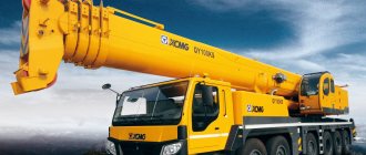
The latest addition to the Chinese company XCMG's crane line is a combination of the design features of XCMG wheeled cranes and crawler cranes: the XGC series of telescopic boom crawler cranes with a lifting capacity from 25 to 220 tons. The new series of crawler cranes are said to be easier to deploy into work position and easier to transport compared to previous models.
According to XCMG representatives, the Asian markets, especially Chinese, are currently the most active. In China, the construction equipment market has grown rapidly over the past 12 months. In addition, XCMG management notes an increase in demand for the company's products in India, Indonesia, Thailand, the Philippines, the UAE and Saudi Arabia thanks to the One Belt, One Road program.
With the growth of the oil, gas and minerals market in Africa, demand for XCMG products is also growing in the region. Thus, in 2022, the company received the largest order in its history for crawler cranes in Nigeria - 183 units for a petrochemical project.
XCMG says the wind energy market is driving the development of innovative technical solutions for its crawler cranes. For example, a lifting platform for new crawler cranes was developed and produced specifically for the installation and maintenance of wind turbines with a capacity of 1.5–3 MW. It has also developed a 650-tonne crawler crane designed to lift wind turbines to heights of up to 140 m. The company is currently developing what it calls “ultra-high and ultra-wide boom technology” for a crawler crane capable of lifting wind turbines to heights of up to 160 m. Also underway development of a crawler crane for lifting wind turbines on difficult hilly terrain and cramped construction sites. Plans have been announced to create a crane capable of lifting wind turbines to a height of up to 180 m.
XCMG representatives note high demand for their super-heavy crawler cranes. In 2013, the operation of the crawler crane mod. XGC88000 with a capacity of 4000 tons, and in December 2022 the second XGC88000 was manufactured and sold.
Perfect automation, long booms
Your new crawler crane mod. SANY Group SCC8260 with a capacity of 260 t in 2022. The maximum length of the main crane boom is 92 m, the longest combination of boom + uncontrolled jib is 62+42= 104 m. The combination of boom with a steerable jib is 62+63=125 m. Maximum load moment – 1470.4 tm. Using a hydraulic drive, the crane is capable of independently unfolding into the working position and folding, removing and installing counterweights, etc. The design includes devices that simplify the repositioning of ropes. Engine power – 336 kW (450 hp).
During transportation, the overall dimensions of the crane are: width - 3 m, height - 3.2 m, and weight is only 45 tons.
Types of taps
The first type is universal tracked vehicles that can be used both as a crane and as an excavator. It is enough to change the equipment from crane to excavator. The lifting capacity of such machines ranges from 5 to 63 tons, among them there are models with improved performance characteristics for installation. These are models E-652B - diesel, E-10011E - diesel crane with a turbo transformer, E-2505 - diesel-electric direct current crane and E-2503 - direct current electric crane.
The second type is self-propelled jib crawler cranes with a lifting capacity of 20 - 63 tons. They are made on the basis of excavators. These models perform excellent construction and installation work: E-1252B, and diesel E-2508.
The third type is self-propelled jib cranes with a lifting capacity of 10 - 160 tons, types DEK, SKG, MKG.
A separate type of cranes are cranes with short booms. They are used where a long boom reach and high height are not needed. Namely, for mounting structures in pits, in the underground part of buildings, for loading and unloading any cargo - equipment, containers, packaged cargo, etc. It is important that, if necessary, the booms of such cranes can be extended and used for work on the installation of building structures to the full height and reach of the boom within the specified characteristics of such models.
All crawler cranes with a lifting capacity of no more than 25 tons are operated by one crane operator. If the lifting capacity is higher, according to ETKS and ENiR, two people are required - a crane operator and an assistant.
Domestic
Tradition and modern quality
In the domestic crane industry, the leader in the production of crawler cranes is Chelyabinsk Mechanical Plant OJSC (ChMZ) . The company produces a fairly extensive line of machines with a diesel-electric drive (which has certain advantages over a hydraulic drive in operating conditions in Russia) with a lifting capacity from 25 to 100 tons, with a boom length from 17 to 70 m. Several types of attachments can be installed on any crane: a mast pile driver, hammer, grab, electromagnet, drilling equipment, as well as other types of equipment upon customer request. The equipment is designed to operate at temperatures from –40 to +40 °C, in difficult climatic conditions. An important point in the operation of cranes: their transportation to their destination is carried out only on special vehicles. The network of dealer and service centers of ChMP covers the whole of Russia.
Among the new products of the enterprise we can name the updated crawler cranes DEK-801 (lifting capacity 80 t), DEK-501 (lifting capacity 50 t), DEK-401 (lifting capacity 40 t). All of them have modernized rotating and running gears and have improved cargo-height characteristics.
Another new product of ChMZ is the DEK-361 crawler crane (lifting capacity 36 tons). The key feature of the model is the new design of the main boom and additional boom equipment. Due to the use of high-strength steel in the design of tubular booms, it was possible to reduce the weight of the boom equipment, which made it possible to achieve high cargo and altitude characteristics. The height of the DEK-361 tower reaches 32 m, and the length of the shunting jib is 25 m. Such characteristics of the tower-jib equipment make it possible to lift loads to a record height for similar domestic cranes (lifting capacity 36 tons) - up to 55 m! In addition, by changing the angle of inclination of the tower, a record reach for cranes with this boom length was achieved - 42 m.
In 2022, ChMZ, in collaboration with MK Vityaz JSC (Ishimbay), manufactured and sent to the customer a unique crane on a crawler chassis mod. KS-5772 lift capacity 25 t with a 105 hp engine. The length of the telescopic boom varies from 9.6 to 28.1 m. A two-link DT-30PMNK2 cross-country tracked chassis with a stationary side is used, forming a boat that protects the crane installation from water during wading and swimming. The warm, spacious cabin can accommodate an entire repair team. The supports of the crane installation also have an innovative design; they are hidden in the body of the “boat” and have a non-standard extension scheme. The crane travel speed on land is 35 km/h, and on water – 4 km/h. KS-5772 is designed for repairing power lines in the Far North.
Lattice and telescopic booms
JSC Klintsovsky Truck Crane Plant (KAZ) mastered the production of crawler cranes not so long ago. Their design is based on the design of cranes produced in the GDR, and the reputation of German machines speaks for itself. Today, the company offers three models of RDK crawler cranes with a lifting capacity from 36 to 50 tons, with a lattice or telescopic boom and a diesel-electric or diesel-hydraulic drive.
A distinctive feature of the design of the mod. The RDK-36 is an undercarriage with telescoping crawler tracks. This allows for a small size during transportation and an increased size of the supporting area when performing crane operations. Due to the specific design of the tracked undercarriage and the developed support contour that the tracked trolley forms in the working position, the crane has a single load characteristic throughout the entire 360° sector and can move with a load on the hook, the mass of which is 10 tons.
The second important feature of these cranes is the design of the crane portals. Their design is thought out in such a way that when installing and dismantling the crane on a construction site, there is no need to re-reinforce the rope: once done, it ensures the transfer of the crane from the transport position to the working position and back. In addition, the rear (small) portal allows for hanging counterweights. Thus, the crane autonomously, without the use of additional lifting equipment, provides its own assembly and disassembly.
The third feature is the design of the rotating part of the cranes, which has high volumetric rigidity, thereby guaranteeing long-term operation of the mechanisms built into it without distortions or damage. At the same time, the layout of the rotating part provides easy access to all crane mechanisms and hydraulic system components for inspection and maintenance.
Another advantage of the RDK-36 crane is its low transport height. Even placed on a trailer with a typical platform height of up to 900 mm from the level of the road surface, it fits into a transport clearance of up to 4 m in height. Similarly, the length of the crane is determined from the conditions of ease of transportation on standard trailers.
The crane has a main boom of a lattice structure with a length of 15 m, which, due to quick-release sections-inserts 5 or 10 m long, is increased to a length of 40 m. The use of high-strength steels ensures, given the accepted dimensions of the boom elements, its sufficient strength when working with loads even on a site with a slope 3°. To expand the scope of use and increase the size of the sub-boom space, rigid jib with a length of 1; 5 or 10 m. In this case, the crane can operate with two cargo winches, one of which is operated on the main boom, and the second on the jib. The crane's lifting characteristics have been raised to new heights and significantly exceed those of domestic analogues at any point in the working area. Safe operation of the crane is ensured by a complex of modern instruments and devices.
RDK-50T is a crawler crane with a telescopic boom. This design reduces the time it takes to prepare a machine for delivery to a site compared to lattice boom cranes. The RDK-50T is more compact than a truck-mounted crane and has higher load-height characteristics, especially at medium and long boom radii. The RDK-50T is capable of moving with a load on a hook and telescoping a boom with a load, working with a load on slopes up to 30°, and performing various jobs using interchangeable attachments.
Durable and time-tested
Yurginsky Machine-Building Plant LLC (Yurga, Kemerovo region) produces Yurginets cranes on a tracked chassis mod. KS-5671, KS-5671-2 capacity of 25 tons, which cannot be called a new product. Nevertheless, these are durable and repairable cranes. The chassis is from a commercially produced tractor with a wide track of 600 mm. The boom is telescopic, provides a lifting height of 20.5 m, with an extension – 27.4 m. The maximum telescopic load is 4.5 tons, with an extension – up to 2.4 tons. Travel speed – 10 km/h. The total weight with extension is 25 tons. The models differ only in engine power - 95.5 and 130 hp. and the size of the working area: 290 and 360°. Operating temperature – from –40 to +40 °C.
The main feature of the Yurgin models is the presence on all cranes of hydraulic servo control with two joysticks, two axial piston pumps, a dual-circuit hydraulic circuit and a mobile hydraulic drive, which allows you to combine up to four crane operations simultaneously and ensure ease of control. There is no need to reposition the cargo rope when working with loads using a telescopic boom. All work is carried out with sixfold reserve.
The plant warns buyers: they should be careful when purchasing taps, as there are many enterprises offering counterfeit products under the Yurginets brand.
Other domestic enterprises, which a few years ago also produced crawler cranes, such as Ulyanovsk Mechanical, have now (against the backdrop of a “growing” economy, according to official statistics) either completely stopped working or have stopped producing products and are only engaged in repairs / restoration of old taps. IMZ AVTOKRAN LLC looks more optimistic - the company is recovering from the crisis and in the future, perhaps, will resume production of crawler cranes.

