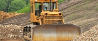
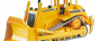
A bulldozer is an earth-moving machine capable of moving independently and efficiently excavating soil or other rocks. The equipment has a simple configuration. The main part is a tractor or tractor, combining a powerful chassis and a cabin with controls. The working unit of the bulldozer is represented by a curved profile blade located outside the main structure. High productivity, the ability to move large volumes of rock and the ability to perform various types of tasks have ensured the demand for this equipment in many areas.
Areas of use
Today, bulldozers are actively used in road construction, construction, mining and other enterprises. The ability of equipment to cut, dig and move soil, rocks and other bulk materials is also used to mechanize such types of work as:
- leveling of territories and cleaning of gentle slopes;
- removal of fertile soil during construction site preparation;
- creation of shallow channels;
- arrangement of embankments;
- cleaning the bases for the foundations of structures;
- development of soil on slopes;
- filling trenches and other depressions;
- clearing the mining area;
- clearing large areas of debris, stones, snow, etc.
Clearing the area
Clearing the area of bushes, uprooting stumps and removing large boulders is carried out using bulldozers with specialized blades. Cutting of small bushes and small trees is carried out using bulldozers-bush-cutters; the collection of cut vegetation is carried out by uprooters with blades adapted for this purpose. Small growth can also be removed with a conventional bulldozer.
Stump uprooting is carried out by uprooters after trimming the remaining roots. For removal of large numbers of stumps, uprooter-gatherers are well suited, and blades with teeth make it possible to remove remnants of the root system from the soil. Large stones are removed using a collector-uprooter. Particularly large boulders are first excavated and a trench is prepared for their movement.
Tree felling is carried out using heavy bulldozers. If the tree is difficult to fell, trimming the roots on three sides helps. To increase pushing efficiency, the blade is raised to the maximum possible height. To enhance the impact, in some cases it is necessary to create an additional embankment in the place where the bulldozer will be located so that the point of application of force to the trunk is located as high as possible.
Types of bulldozers
By appointment. This criterion determines the possibility of using bulldozers for certain types of work. The technique is:
- general purpose – designed for earthmoving, planning and construction tasks;
- specialized - such bulldozers are used in underground or underwater mining.
According to the type of climate control. This feature indicates the ability to operate machines in certain climatic zones. Bulldozers may have a non-standard design:
- with adaptation for work in low temperature conditions (up to -50 degrees);
- with adaptation to the tropical climate (temperatures up to +45 degrees and increased precipitation).
On the chassis. The type of chassis determines the ability to move equipment on different types of surfaces. A modern bulldozer may have the following movable base:
- tracked – effective for use in off-road conditions;
- wheeled – Suitable for frequent travel on public roads.
By dump type. The shield, the main working part of a bulldozer, can have different designs and mobility. Depending on the model, the equipment is equipped with the following types of dumps:
- non-rotating – installed perpendicularly and moves up/down;
- rotary – mounted at an angle in a horizontal or vertical plane;
- universal - consists of two halves, makes turns in different directions.
According to the lifting drive mechanism. This feature determines the maneuverability of the working body of the bulldozer (turning, lowering, skewing, tilting). The lifting mechanism can be:
- hydraulic – consists of hydraulic cylinders;
- electromechanical – has a combined configuration;
- mechanical - includes a winch and a system of rope blocks.
Roman Alexandrov is interested in:
Please tell me which of the jobs performed by a bulldozer are the most popular?
Our expert answers:
A bulldozer is a universal earth-moving and transport equipment. It is equipped with a blade having a curved shape, which is fixed to the frame. This specialized machine is used to perform a wide range of earthmoving, leveling, transport, and cultural operations. It is used both independently and in combination with other earthmoving and land reclamation equipment.
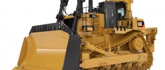
Cat® Bulldozers
- Cat D6R2
Crawler bulldozerEngine Model Cat C9 ACERT™ Net Power 141 kW Operating Weight 18,984 - 21,613 kg
Price request
Crawler bulldozer
Engine Model Cat® 3406C DITA Net Power 239 kW Operating Weight 37,557 kg
- Price request
Other models
The American brand Caterpillar is one of the world leaders in the production of powerful and efficient special equipment. The rental and sale of bulldozers of this brand are in great demand: the machines are actively used in different climatic and working conditions. The Cat® brand includes a variety of crawler models. Among the presented machines, you can choose a bulldozer of small, medium and high power with the optimal blade size and productivity. If necessary, the equipment can be equipped with replacement equipment (rippers, extenders, openings, slopes). Learn more about the range and features of Cat® bulldozers here.
Cat® D3K2
The Cat® D3K2 Crawler Dozer is designed for a variety of earthmoving applications. It can carry out layer-by-layer digging and moving soil, mining, territory planning when arranging green areas, etc.
The D3K2 model has advanced capabilities. A set of new functions includes slope indication, automatic blade setting when working on slopes, traction control and a number of others. The dozer is equipped with the AccuGrade™ system, which allows the operator to cut and fill soil with high accuracy without additional site measurements.
The Cat® C4.4 ACERT diesel engine meets Tier 3 exhaust emissions requirements. The crankshaft speed can be adjusted to suit operating conditions, reducing fuel consumption by up to 25%.
Cat® D5R2
The D5R2 model is designed for excavation work in difficult conditions. The bulldozer has a raised drive wheel, which makes the machine more stable on rough terrain. The installed VPAT system allows you to adjust the angles of inclination and rotation of the blade, ensuring high accuracy of soil movement. The electronic gearbox has 3 + 3 speeds, which can optionally be increased to 5 + 4. Differential control allows fast and precise turning even with the heaviest blade load.
To select the direction, a “one-way” control lever is installed. Automatic adjustment of operating parameters is provided. The cab has increased visibility and built-in rollover protection system (ROPS).
The Cat® D5R2 Dozer's maneuverability and precision ground-moving capabilities make it suitable for use in confined areas or clearing areas.
Cat® D7R
The Cat® D7R Crawler Dozer features a raised drive wheel for good traction and stability, even in difficult terrain. Built-in electronic systems (AccuGrad™) improve excavation accuracy without requiring additional markings on the ground. Differential control allows the bulldozer to turn quickly, even with a heavy blade load.
The display (Caterpillar Monitoring System) shows current parameters and operating data. All instrument panel indicators are clearly visible even in bright sunlight. Thanks to the monitoring system and three warning levels, the operator has all the information about the current state of the equipment without being distracted from the work at hand.
The bulldozer is equipped with a pressurized cabin mounted on damping supports. Large windows provide good visibility. For operator convenience, the seat is turned 15 degrees to the right.
Cat® D9T
The D9T is designed for use in harsh conditions. The powerful Cat® 3408C engine handles everything, including loosening tough or compacted soil. The volume of a full fuel tank is enough to work non-stop throughout the entire working day.
For ease of maintenance, the main components of the bulldozer have a modular design and can be easily removed for repair or inspection. Machine diagnostics are performed using the Cat® Electronic Technician system.
The cabin is installed on damping supports, which reduces the overall noise level (by 2 dB). The Advisor control system monitors the current parameters of the bulldozer and displays them on the display. The backlighting of the keyboard and switches has day and night modes. The cabin has a built-in air conditioning system that maintains a comfortable temperature.
Functions of special equipment
This special equipment is widely used in winter. Such machines are capable of effectively cutting bushes, small forests, and clearing the roadway of snow. But the main task that the bulldozer performs is the development of territories, which is carried out in several stages:
Traction class bulldozer
- cutting and collecting soil using the main working tool;
- moving cut layers to the laying site;
- laying the soil in the required place, which is planned based on the markings made;
- returning special equipment to the mine face to its original position.
In order for the operation of a specialized machine to be effective and occur without downtime, its driver must clearly know the dimensions of the planned structure and its placement in space. Therefore, working with a bulldozer requires appropriate skills and knowledge, extensive experience and high qualifications.
Video: Working on the Chetra T-35 bulldozer
Publications on the topic
Technology for laying paving slabs on concrete
DIY paving guide
Question No. 12 - What types and types of aerial platforms are presented in Russia?
Bulldozers. Purpose and classification. Scheme of work
Purpose and classification. A bulldozer is an earth-moving machine consisting of a base tractor and bulldozer (attached) equipment, designed for cutting and moving soil, as well as for leveling the surface being developed. Bulldozers perform the following work: developing and moving soil, leveling areas, leveling soil dumped by other machines; construction of embankments and development of soil filled by other machines; construction of embankments and development of excavations during the construction of roads and railways, when constructing canals, etc.; backfilling ditches, canals, water supply, sewer and other trenches; maintenance of warehouses of sand, crushed stone, stone, etc.; clearing areas of snow, stones, stumps, trees, construction waste; pushing scrapers while loading them. For most modern crawler bulldozers, the economically viable range of soil movement currently does not exceed 60-80 m; for wheeled bulldozers it is 100-150 m. Bulldozers are classified: - by purpose - into general purpose bulldozers, adapted for work in various soil conditions and in moderate temperature (from -40°C to +40°C), and for special-purpose bulldozers designed to perform special work in quarries, etc. at temperatures from -60°C to +60°C; - according to the type of propulsion of the base vehicle - tracked and wheeled; – along the longitudinal axis of the base machine, rotary blades at an angle of up to 60° in plan (in both directions) of the longitudinal axis of the machine and up to 10-12° to the vertical axis. The rotary blade is attached to the frame with a ball heel and two rods, with the help of which you can change the angle of installation of the blade in two planes relative to the pushing frame. Bulldozers with a fixed blade move soil only forward in front of the blade, while universal bulldozers (with a rotating blade) can move soil both in front and in both directions, which makes it possible to fill trenches and develop ledges. In recent years, bulldozers with an active working body with a re-explosive device have been introduced into practice. The developed soil is loosened and thrown from the dump by a stream of gases formed during combustion of the working mixture - gasoline (or diesel fuel) and air - in a special chamber. A bulldozer with an explosion chamber in medium-hard soils develops a productivity 20 times greater than that of conventional bulldozers. The energy intensity of the process of forming a drawing prism and moving soil is influenced by the geometry of the dump. In Fig. 62 shows a diagram for constructing a blade profile and shows the values of its main parameters. The smaller the cutting angle y, the lower the energy intensity of the soil cutting process. However, the cutting angle y cannot be set less than 50°, since for normal operation of the blade it is necessary that the clearance angle be at least 30°. This value of the rear angle is necessary because when the bulldozer operates on a surface with sharply changing slopes, the blade can rest on the rear part. When the clearance angle is less than 50°, a slight sharpening angle is obtained, which affects the strength of the cutting part of the knife. The angle p0 between the horizontal and the tangent of the upper edge of the dump determines the conditions for the collapse of soil moving up the dump. As this angle decreases, the radius of curvature of the upper section of the dump becomes smaller, which increases the resistance to soil movement along the dump and increases the normal component, under the influence of which the soil is pressed against the dump. The blade inclination angle e0 determines the shape of the drawing prism. At a small angle of inclination of the blade, soil can spill over the blade, since in many cases the drag prism will be higher than the blade. As this angle increases, the conditions for soil movement up the dump worsen, adhesion increases and the overall energy intensity increases. The angle of installation of the visor affects the formation of soil chips in the upper part, as well as the volume of the drawing prism: it is taken equal to 90-100°. The height of the Yak blade with a visor determines the volume of the prism of soil collected on the dump. The length of the fixed blade (at least 50 mm on each side) is determined taking into account the overlap of the width of the base machine or the elements of the pushing frame that most protrude to the sides. The length of the rotary blade (at least 50 mm on each side) is selected based on the overlap of the clearance along the width of the base machine or pushing frame with the blade rotated as much as possible in plan. The height of the straight section of the blade a is usually equal to the height of the knife, and this section has a significant influence on the formation of chips. The increase in the productivity of bulldozers is significantly affected by the use of openers, which are attached by rods or controlled by hydraulic cylinders from the driver’s cab. In order to reduce soil loss, it should be transported along the same track, which contributes to the formation of rollers on the sides that protect against loss of soil during subsequent passes of the bulldozer. Moving soil in a trench also increases the productivity of the bulldozer, since the loss of soil from the drawing prism is insignificant. When bulldozers operate in tandem, due to an increase in the drawing prism, the productivity of bulldozers increases by 20%. The distance between the edges of the two dumps is 20-25 mm. The way work is done greatly influences the performance of bulldozers. Thus, cutting with thin chips is used in the development of all types of soils, when cutting on an incline and for soils with significant cutting resistance. The comb method with transverse deepening and deepening of the blade blade is used in the development of hard and dry soils with an average cutting resistance. The wedge method with the transition from the largest cut to the smallest is used when developing several soils. When lifting 10%, the productivity of bulldozers decreases by 40-50% compared to productivity on a horizontal section, and when working downhill, productivity increases. Technological scheme of work. The operation pattern of bulldozers is determined by the nature of the structure being built, the relative location of the sites for excavation and dumping of soil, as well as local conditions. The most common and widespread soil development scheme is the shuttle. The main types of work performed by a bulldozer: felling trees; removing the plant layer and placing it in a roller; moving soil into the embankment from lateral reserves; moving soil into the embankment from the excavation; cutting slopes of deep excavations; channel arrangement; backfilling of trenches (pipes); leveling the soil in the embankment; arrangement of ramps on large slopes, filling of holes and ravines; installation of half-cut-half-fill on slopes; reserve bottom layout; site layout; embankment slope planning using a planner. Automatic bulldozer control. The work process of bulldozers is characterized by periodic repetition of sequential technological digging operations. The amount of resistance overcome by the machine varies over a wide range. Digging is the most stressful cycle, where sharp fluctuations in load are observed. Manual control of bulldozers is associated with great stress for the driver, since the number of handle switches per hour can reach 1,500-1,800, and the force for each switch is on average 147.15 N. Increasing the productivity of bulldozers and facilitating the driver’s working conditions can be achieved through automation of machine control . The main types of automatic control of bulldozers are: push-button control of shift levers; automatic control of soil cutting mode.
In recent years, the Avtoplan-P equipment complex has been widely used for automatic control of bulldozer operation.
Rice. 63. Diagram of the automatic control system for the blade of the bulldozer DZ-54 “Avtoplan”: 1 - drain pipeline into the tank; 2 - pipelines for supplying liquid under pressure; 3 - check valve with throttle; 4 — pipeline for supplying liquid under pressure; 5 — engine speed sensor (tachogenerator); 6 — pendulum angular position sensor; 7 — control panel; 5 - overload block; 9 — control unit; 10 - battery; 11 — reversible electric spool; 12— drainage pipeline
A tachogenerator is installed on the engine, and when the engine speed drops to the nominal speed, an overload signal is sent to the control unit, after which the bulldozer blade is automatically deepened to a certain height. The DUP-R sensor is an angular position sensor and is installed either on the push bar or on the blade. The main unit in the angular displacement sensor is a pendulum, which, when the position of the blade changes, gives a signal to the potentiometer winding. A control unit of the BUP-1 type, as a rule, is installed in the driver’s cab and with the help of one handle the slope is set, and with the help of the other the working element is deepened. The command to the working hydraulic cylinders is issued by the spool. The ZSU-5 type electric spool is controlled by electromagnets, which switch the pilot spool plunger, thereby opening the oil pipeline to the working hydraulic cylinders. In Fig. 63 presents the Autoplan automatic control system, which ensures high quality work and also provides automatic control of the engine mode based on the number of revolutions.
The automatic control system includes: a pendulum angular position sensor mounted on push bars near the support hinge, an engine speed sensor; control panel, overload unit, control unit, batteries, reversible spools, check valve with throttle.
On the control panel, the angle of inclination of the push bar determines the position of the cutting edge of the knives at the level of the supporting surface of the tracks. The pendulum sensor sends an electrical signal to the control unit, after which current flows into the corresponding electric spool, the solenoid of which moves it to the desired position and ensures the supply of working fluid to the corresponding cavity of the hydraulic cylinder.
A check valve with a throttle regulates the speed of lowering the blade when the machine is operating.
The use of an automatic system for regulating the work process of a bulldozer reduces operator fatigue and increases productivity by 20-25%.
—-
Bulldozers are designed for layer-by-layer cutting and moving soil during the construction of road embankments and excavations, leveling soil dumped by excavators, scrapers and other machines, and leveling construction sites. Along with this, bulldozers clear the area of bushes and large stones, uproot stumps, fell trees, and clear snow from roads and streets. Bulldozers are also used as pushers of scraper units in the process of collecting soil.
Bulldozers are mounted, in the form of a blade with a knife, equipment for tracked tractors, wheeled tractors and can be used as a replaceable working tool on motor graders, excavators and other road construction machines.
The main parameters of bulldozers are the width and height of the blade. The cutting angle for rotary blades is 27°, and the recommended cutting angle for all bulldozers is at least 55°. When constructing embankments and dumping soil, an important parameter is the amount of rise and fall of the dump (from the supporting surface).
Depending on the power of the base tractor (tractor) and design, bulldozers can work on a wide variety of soils, from swampy to rocky. When working on heavy and rocky soils, bulldozers are equipped with rippers.
Bulldozers are classified by purpose, type of chassis, traction force of the tractor (tractor), blade design and type of drive.
Depending on the functions performed, we can distinguish general-purpose bulldozers that carry out excavation, leveling and other construction work in normal soil and climatic conditions, and special ones designed to perform special work - leveling cavaliers, for underground and underwater developments, etc. The machines can be in northern and tropical versions.
Based on the type of chassis of the base machine, a distinction is made between tracked and air-wheeled bulldozers. Crawler bulldozers are effective at moving soil over a distance of up to 80-100 m, and pneumatic-wheeled bulldozers - over a distance of up to 120-150 m.
GOST 7410-70, depending on the nominal traction force, provides for six standard sizes of crawler bulldozers with fixed and rotary blades of classes 4, 6, 10, 15, 25 and 35 tf. The fleet of road construction machines also includes 3 tf class bulldozers on agricultural tractors.
The type of wheeled bulldozers includes six standard sizes of machines with a nominal traction force of 0.9; 1.4; 3; 6; 9 and 15 tf, power 40-55, respectively; 50-80; 130—150; 180—200; 240-300 and 375-430 l. With.
Pneumatic wheeled bulldozers D3-37 (D-579) and DZ-48 (D-661) (in small quantities) of the 3 tf class are produced in series; crawler bulldozers DZ-29 (D-535) and DZ-42 (D-606) of 3 tf class; DZ-101 class 4 tf; D3-53 (D-686), DZ-54S (D-687S), DZ-27S (D-532S) (in small quantities), DZ-17 (D-492A) and DZ-18 (D-493A) class 10 tf; DZ-24A (D-521A), DE-35S (D-575S), DZ-25 (D-522) (in small quantities) of the 15 tf class and DE-34S (D-572S) of the 25 tf class. Pneumatic wheeled bulldozers DZ-102, tracked bulldozers DZ-104 of class 4 tf and DZ-109 of class 10 tf, as well as bulldozers on tractors T-220, T-330 and T-500 of class 15, respectively, are being mastered; 25 and 35 tf. The technical characteristics of bulldozers are given in table. 4.3—4.5.
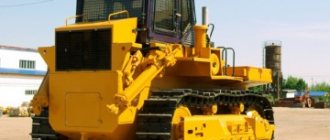
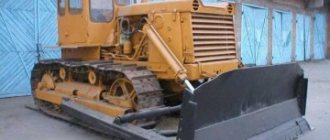
Based on the design of the blade, a distinction is made between equipment with a fixed blade (Fig. 4.15), permanently installed at a right angle to the longitudinal axis of the base machine, and with a rotating blade (Fig. 4.16), which can be installed at a certain angle in the horizontal and vertical planes. Bulldozers with a rotary blade are often called universal.
Depending on the purpose, blades can have different shapes, as well as attached visors, extenders, flaps, and a protruding middle knife.
According to the type of drive for raising and lowering the blade, bulldozers are distinguished with cable (see Fig. 4.15) and hydraulic (see Fig. 4.16) control.
The main components of the bulldozer are the blade, the pushing device and the blade control system.
The blade (Fig. 4.17) is a welded structure consisting of a frontal sheet, a visor, lower and upper stiffener boxes, ribs,
welded to the bottom box, side walls and lugs that serve to connect the blade to the pushing device.
The frontal sheet is welded from two sheets: the upper one, bent along a radius of a certain curvature, and the lower one, straight, located obliquely to the horizon, usually at an angle of about 60°. Replaceable knives are bolted to the bottom sheet - two outer ones 1.3 and one middle one, which have double-sided sharpening, which allows you to turn them over or swap them as they wear out. In order to increase durability, wear-resistant surfacing and frost-resistant steels are used in the manufacture of knives.
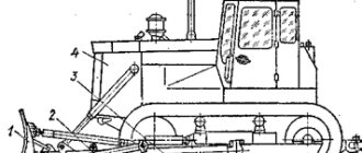
Rice. 4.15. Bulldozer D3-53 with a fixed blade and a cable drive: 1 - drive winch; 2 front pillar; 3 fixed clip of the pulley; 4 - guide block; 5 - screw braces; 6— movable clip of the pulley; 7 - blade; 8 - knives; 9 - push bars
Rice. 4.16. Bulldozer DZ-18 with a rotary shaft and hydraulic drive: 1 - blade: 2 - universal frame; 3 — hydraulic cylinders for raising and lowering the blade; 4 - pusher
Rice. 4.17. Bulldozer blade DZ-18: 1 - rightmost blade; 2 - middle knife; 3 - leftmost knife; 4 - cover; 5 - vertical connection; 5 — visor; 7 upper rigidity box; 8 — frontal sheet; 9th century lower stiffening box; 10 — fastening fingers; 11 - ball socket
The lower stiffening box is made of sheet steel, usually in the form of a triangular prism. The top box is a square beam. The vertical rigidity of the blade is created by the connections. Eyes are welded at the back of the blade to attach it to the push bars and braces. Extenders can be installed on the side cheeks of the blade to increase the volume of soil moved. A visor, reinforced with ribs, is welded to the top of the front sheet, preventing soil from spilling over the dump during lifts and jolts.
For bulldozers of the 3 tf class (DZ-29, DZ-42, etc.), a bracket is welded at the back in the middle of the blade for pivoting the blade with the hydraulic cylinder rod, the head of which is equipped with a ball bearing. For bulldozers of the 10 tf class with a fixed blade (DZ-54), the latter is equipped with eyes for connection with hydraulic cylinder rods, push bars and braces.
For bulldozers of the 10 tf class with a rotary blade (DZ-18), a ball socket equipped with a plate is welded into the box for connection to the ball head of the universal frame. Eyes with pins are used to connect the blade to the pushers. For bulldozers of the 15 tf class (DZ-25), instead of a ball socket, the blade is equipped with an eye, which fits onto the head of the universal frame and is pivotally connected to it with a vertical pin. The blade has additional eyes at the edges for connection with the hydraulic cylinder rods for turning the blade in plan.
For bulldozers with a fixed blade (D3-53), it is attached to two push bars located on both sides of the tractor (tractor). Push bars are rectangular or circular beams with lugs for mounting a blade and braces, as well as for attaching bulldozer equipment to the base machine.
The connection between the blade and the beams can be rigid or articulated. In the first case, for bulldozers of the 3 tf class (DZ-29, etc.), the push bars are welded to the blade. Fork catchers are welded to their opposite ends. Using catchers and pins, the push bars are pivotally connected to cylindrical pins at the ends of the transverse beam. The latter is attached in the middle of the tractor to the frame side members using two stepladders and stops that prevent it from moving in the longitudinal direction.
In another case, for bulldozers of the 10 tf class (DZ-54, etc.), the blade is connected to the push bars using screw braces 5 of tubular cross-section, which provide a change in the cutting angle (within 10°) and the transverse skew angle (within 4°) . To connect with the support hinges of the push bars, plates with support pins are installed on the frames of the crawler bogies. The 25 tf class bulldozer (DE-34S) has spherical support joints for push bars.
For bulldozers with a rotary blade, the pushing device is made in the form of a pushing frame, on which, in addition to the bulldozer, other replaceable working equipment (brush cutter, uprooter, etc.) can be installed. Such a universal frame (Fig. 4.18) is a welded horseshoe-shaped structure of two box-section semi-frames connected to each other by a sheet and a ball head. To connect to the hydraulic cylinder rods, lugs are welded on top of the half-frames, an lug is used to connect the frame to the block frame, and brackets are used to connect to the pushers. With the supports welded to the track frames, the frame is connected with lugs and pins.
The pushers are made in the form of box-shaped or tubular cross-section beams and screw braces, which are interconnected by hinge joints, providing the ability to change the distances between the attachment points to the frame and the blade. The pushers are connected to the eyes on the blade using fingers and crosses. An insert with an internal thread is welded into the brace pipe at the front, and a bushing with an eye at the rear; in the middle, a handle passes through the pipe, with the help of which the length of the brace is changed. The threaded part of the brace screw is protected from dust by a seal.
Using a screw with a fork, the beam is connected to a kingpin mounted in a bracket on the frame. The rods of the hydraulic cylinders for tilting the blade are fixedly fixed on the guides. The sliders, and with them the support pins of the universal frame, move as a result of the movement of the cylinder liners.
Rice. 4.18. Universal frame of the bulldozer DZ-18: 1 - half frame; 2 — bracket for connection with the pusher; 3 — eye for connection with the hydraulic cylinder rod; 4 - ball head; 5 — eye for connecting to the block holder; 6 — frame eye; 7 - support
For bulldozers with a rotary blade of the 4 tf class (DZ-104) and bulldozers of the 25 and 35 tf classes being developed, the angle of rotation of the blade in plan, as well as its skew angle, is changed using hydraulic cylinders. In this regard, the design of the universal frame has also been changed. Thus, in the DZ-25 bulldozer (Fig. 4.19), instead of brackets for connecting with pushers, the frame has guides on the sides along which the pusher slides move. The guides have grooves into which clamps for positioning the blade in plan are inserted. In addition, there are eyes on the frame for connection with hydraulic fluid when supplying working fluid to different cavities of the corresponding hydraulic cylinders.
The main working movements of the bulldozer consist of lowering and raising the blade using a cable or hydraulic drive.
The diagram of the rope drive is shown in Fig. 4.20. It consists of a winch and a system of blocks that serve to supply the rope from the winch to the blade and form a pulley, which increases the traction force of the winch several times. Bulldozers are usually equipped with single-drum winches (on the rear axle of the tractor), which are driven from the power take-off shaft through the connecting shaft.
Rice. 4.19. Bulldozer D3:25: 1 - knives; 2 — visor; 3 - dump; 4 — hydraulic cylinders for raising and lowering the blade; 5 - tractor; 6 — guides of the sliders of the support fingers; 7 — support hinges; 8 — hydraulic cylinders for blade skewing; 9 — guides of the pusher slides; 10 universal frame; II - pusher slider; 12 — pushers; 13 — hydraulic cylinders for turning the blade in plan; 14 — headrest; 15 - pin; 16 and 17 "" lugs
Rice. 4.20. Scheme of the bulldozer rope drive: 1 - winch; 2 pneumatic cylinders; 3 — tractor power take-off shaft; 4 — winch control handle; 5 — guide blocks; 6 — pulley block; 7 - drum with spare rope
Rice. 4.21. Diagram of the hydraulic drive of the bulldozer: 1 - hydraulic distributor; 2 -. metal pipelines; 3 - transfer pipe; 4 high pressure hoses; 5 — hydraulic cylinders for raising and lowering the blade; 6 — hydraulic cylinders for turning the blade in plan; 7 hydraulic cylinders for blade skewing
For bulldozers with a drop-block control system (see Fig. 4.15), to install block cages, a front pillar 2 is equipped, consisting of two vertical beams connected at the top by a transverse beam, and at the bottom by a strip. To protect the radiator, a shield is attached to the front of the rack.
If there is a hydraulic drive, the raising and forced lowering of the blade is carried out using hydraulic cylinders. The hydraulic drive (Fig. 4.21) is carried out from the hydraulic system of the base tractor through a hydraulic distributor, a system of pipelines, flexible high-pressure hoses and hydraulic cylinders. Double-acting hydraulic cylinders provide lifting and lowering of the blade, its fixation in the required position and the so-called “floating” position, in which the blade, under the influence of its own weight, can take any position, resting with knives on the ground surface.
Along with raising and lowering the blade, the operations of transverse skewing of the blade, changing the cutting angle, rotating the blade in plan, and in some cases also the installation angle of the extensions are hydraulically activated.
Basic tractors have mechanical, hydromechanical (T-220, T-330 and T-500 tractors) or electromechanical (DET-250 tractor) transmissions.
For domestic bulldozers, an autonomous control system has been created, such as “Avtoplan-1”, which does not require the use of external guides and ensures stabilization of the given angular position of the blade push bar in the longitudinal plane. The system is installed on bulldozers of the 10 tf class (DZ-18, DZ-54) and on bulldozers of the 4, 15, 25 and 35 tf class that are being developed. The system is created on the basis of a complex of unified instruments and controls.
Depending on the slope of the surface, the angle of inclination of the push bar is set on the control panel, corresponding to the position of the cutting edge of the blade knives at the level of the supporting surface of the tracks. When the angle of inclination of the push bar changes, the angular position sensor sends an electrical signal to the control unit. This signal is converted and supplies current to one of the electric spools; as a result, the working fluid enters the corresponding cavities of the lifting and lowering hydraulic cylinders and the blade.
Bulldozers can be equipped with various types of replaceable working equipment. These include extenders, openers, a protruding middle knife, skis, extensions for bulldozers of classes 15, 25 and 35 tf, loosening teeth, knives for frozen soils for bulldozers of all classes except 4 and 6 tf, brush cutting knives, ditch attachments, slopes - planners.
Expanders are used when working in light conditions to increase the volume of soil moved. Openers are used to increase the volume of transported bulk and lump materials when working in light conditions. In some cases, controlled cards are used. Skis are used to facilitate leveling work and work on cobblestone pavements, when it is necessary to limit the possibility of deepening the dump. Extensions are used when it is necessary to move certain minerals that have a small volumetric mass. Extensions are practically not used on ground, since the stability of the straight-line movement of the bulldozer and control of the blade are significantly deteriorated due to the large length of the blade.
content .. 81 82 86 ..
Standard cycle of bulldozer work
The working cycle of an earthmoving machine includes a number of sequential operations:
- cutting off a layer of soil;
- creation of a drawing prism;
- moving the soil mass to the storage site;
- stopping equipment with gear shifting and raising the blade;
- reverse;
- stopping, changing gears, lowering the working element.
The type and sequence of operations depends on the task at hand - loosening the soil, vertical leveling, backfilling the pit, leveling the surface.