The KamAZ car manufacturer is trying to make its brainchild reliable. But despite all the reliability, KamAZ equipment still fails. One of these breakdowns is when, when you press the accelerator pedal, the engine does not increase speed at all, sometimes it stalls. A malfunction can happen at any time, catching you by surprise. If the malfunction indicator (check) lights up, this means the engine control unit has entered emergency operation mode. The reasons for this are described below.
Causes of malfunction
Gas pedal KamAZ
- Return valve malfunction
- Malfunction of fuel system sensors
- Airing the fuel system
- Injector malfunction
- Mechanical failure of the fuel pump
- Electrical wiring fault
- Engine control unit malfunction
- Dirty fuel filters
- Speed sensor malfunction
- Gas pedal failure
- Mountain brake malfunction
Symptoms of a problem
Among the main signs of problems are:
- Absence of any reaction to the accelerator after starting the vehicle’s internal combustion engine;
- Dips, loss of throttle response while driving;
- Floating idle speed;
- Sharp jumps in speed when you gently press the accelerator;
- Idle speed too high.
The device contains movable electrical contacts, as well as conductive tracks - these elements are subject to wear during operation. In the operation of the engine, you can observe dips when picking up speed, unstable idling.
Related article: 5 of the best car speakers for high-quality sound
If there is a malfunction in the unit, the driver can see this by a warning light on the dashboard. In such a situation, the ECU will switch the engine to standby mode.
In this mode, you can observe a slow increase in speed, even if you press the accelerator sharply. In addition, the vehicle's fuel consumption may increase significantly.
If two sensors in a unit fail at once, the ECU will switch the operation of the internal combustion engine to emergency mode - the driver will not be able to influence the operation of the engine, the speed under any conditions will be slightly higher than the idle speed.
Engine system diagnostics
Computer diagnostics Kamaz
Our company’s specialists have significant experience in diagnosing KamAZ engine control systems when the gas pedal stops responding. The diagnostician will adequately identify the resulting breakdown. Next, the engine system will be repaired, with the replacement of spare parts, programming, if necessary.
Stories from our practice
Repair
If there are any problems with the pedal, then only a complete replacement of the unit will help. But before changing anything, it is worth identifying the cause of the malfunction. To do this, you can use a multimeter test.
You can disconnect the sensors and the block and remove the pedal. Check the resistance - when you press the gas it should change slowly. Jumps in indicators indicate malfunctions.
But sometimes repairs are possible - for example, the wiring is damaged. If a wiring defect is detected, you can use the following diagram.
The mechanical gas pedal, familiar to many from old domestic technology, is designed very simply. In it, the lever is connected to the carburetor throttle valve with a cable, and when you press the pedal, the valve simply opens stronger and the fuel supply increases. But this simple scheme is outdated. Nowadays, the electronic system is widely used, which has many advantages over its mechanical counterpart. Moreover, on injection engines the mechanical version is very capricious, and the electronics work much better.
Mountain brake failed
The first call came from the village of Chernaya Gryaz, where a KAMAZ almost new 2014 model stopped feeling and detecting its gas pedal. Didn't react to her at all. The situation is quite common and common, but an ignorant person will be completely at a loss as to what to do about this problem. We can agree - yes, there may be a lot of prerequisites for a car not responding to the gas, but still the one that we have identified once again is one of the most common. When connecting to KAMAZ with A-SCAN, we immediately saw that the mountain brake was pressed. This happens in several cases - a wiring break, the valve itself does not work (stuck, rusted, broken), or the driver has a very short memory. Again, the human factor. The car was parked in a service center and apparently one of the service personnel did not bother to unclick the “miner!” button. Well, this is the case for us - we are always happy to help with a professional answer to a question, and at the same time show how it is done. We are also always happy to share our experience.
Adjustment
The adjustment process may vary on different car models, since different manufacturers use mechanisms of different designs. But the same principle can be applied for configuration. As for a specific model, it is better to find information on it in advance.
To begin the adjustment, the first step is to remove the pedal from the holding bracket. Next, loosen the screws securing the cover. One screw holds the cover in a certain position - it must be completely unscrewed. The cover is turned to the side clockwise until the end, then the screws are tightened again.
This adjustment will reduce pedal response time. Some car owners note that after such adjustments, the response speed can even be compared with a mechanical pedal. Adjustment allows you to improve engine performance and improve the start of movement from a standstill.
In cases where a pedal with low sensitivity is needed, it is necessary to rotate the cover in the opposite direction - counterclockwise. The machine begins to respond to presses not so quickly.
Sometimes you can come across harmful adjustment tips - drivers advise placing shims under the lever. This is the wrong approach. Sometimes the pads get caught under the contact pads in the potentiometer, and the machine may lose control as a result.
KamAZ Cummins engine does not respond to gas
Another application KAMAZ 2014 with a Cummins Euro 4 engine with urea periodically stops responding to the accelerator pedal. The car is located in Mitino. After a visual inspection of the engine harness and diagnostics of individual electrical circuits, several shortcomings were discovered: first, one of the connectors of the ELECTRONIC ENGINE CONTROL UNIT was not fixed properly, second, a dropped pin was found in the threaded connector at the exit from the cab, and third, frayed wire insulation in the circuit. air heating, this wire, with a high degree of probability, could be shortened to ground. After all the shortcomings were eliminated, the car was tested for at least an hour, and only then the work was accepted. It turns out that technicians and a truck had already come to this car, they even took it to the technical center, but they couldn’t figure it out. I am very glad that it was our specialists who were able to repair the truck. This work was well paid and the happy customer said that from now on he would only work with our company.
Kamaz electronic gas pedal: device, engine control principle, diagram
ENGINE CONTROL SYSTEM f. “CUMMINS” and models 740.65-240 and 740.62-280 (KAMAZ) - electronic (ECM) containing a microprocessor control unit. The engines use high-pressure fuel injection pumps with an electronic regulator or JSC "YAZDA" (see tables 6 and 7 - "Technical characteristics of engines").
The ECM is designed to control the cyclic fuel supply of the engine depending on the operating modes of the engine, its temperature state, control characteristics and environmental parameters.
The system provides the following functions:
— rationing of starting fuel supply;
— correction of the cyclic supply depending on the charge air pressure;
— limiting the cyclic fuel supply when the maximum coolant temperature is reached;
— control of the starter blocking relay;
— turning off the fuel supply in the “mountain brake” mode;
— cruise control function;
— limiting the maximum speed of the bus;
— providing emergency engine shutdown;
— implementation of diagnostic functions and transmission of diagnostic information through the diagnostic connector via K-line and CAN;
— indication of a malfunction of the ECM with the “CHECK ENGINE” indicator lamp;
— ensuring interaction with other bus control systems;
— provision of emergency warning and protection, etc.
The full list of functions performed by the ECM is determined when designing the product on which the engine is used.
The ECM includes:
— electronic control unit (ECU);
— wiring harnesses complete with sensors, switches and connectors for connecting system diagnostic devices under operating conditions;
— actuators (fuel injection pump rack drive, engine emergency stop valve).
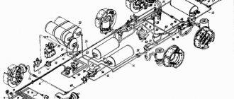
ECM elements and their purpose on KAMAZ engines with fuel injection pump.
Placement of system elements and routing of the engine wiring harness on engines with fuel injection pump f. "BOSCH" are presented in Figure 51.
The system uses the following elements:
Crankshaft speed sensors (main and auxiliary) 0281 002 898 f. “BOSCH” - induction, used to measure the rotation speed of the engine crankshaft and camshaft.
The crankshaft speed measurement sensor is installed in a hole made in the front cover. To generate sensor signals, a special front counterweight of the crankshaft with eight slots is used as an inductor.
The camshaft speed sensor is installed in a special hole made in the flywheel housing. To generate sensor signals, a special wheel with sixteen slots is used as an inductor.
Coolant temperature sensor0 281 002 209 f. "BOSCH" is used to determine the temperature condition of the engine. Installed in the hole in the engine cooling system thermostat box.
The sensor signal is used in the function of limiting the cyclic supply when the permissible engine temperature is exceeded, issuing a warning to the diagnostic lamp and adjusting the starting fuel supply depending on the temperature state of the engine.
Fuel temperature sensor0281002209 f. “BOSCH” - to determine the fuel temperature, mounted in a special valve body installed at the inlet of the fuel injection pump. Depending on its signal, the volume of cyclic fuel supply is adjusted.
Charge air pressure and temperature sensor0 281 002 576 f. "BOSCH", installed in the connecting pipe, determines the temperature and air pressure in the engine intake manifolds. Temperature and air pressure values are necessary to determine the air mass flow.
Electronic control unit MS6.1 f. "BOSCH" provides reception and processing of signals from sensors and switches, information transmitted via the CAN bus.
The ECU analyzes all incoming information about operating parameters, the state of the engine and the bus, processes it in accordance with specified algorithms and controls the fuel injection pump rack, while ensuring the injection of strictly metered portions of fuel.
Via the CAN bus, signals can be exchanged with other bus systems, and system diagnostics are carried out via K-line. The electronic control unit is installed in the bus cabin. The actuators of the system are the fuel injection pump rack movement electromagnet and the 24V retractor solenoid of the engine emergency stop valve.
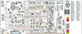
Figure 51 — Installation of the wiring harness on engines with fuel injection pump f. “BOSCH”: 1 — crankshaft speed sensor (main), 2 — camshaft speed sensor (auxiliary), 3 — coolant temperature sensor, 4 — fuel temperature sensor, 5 — charge air pressure and temperature sensor, 6 — engine control system harness, 7 — injection pump rack electromagnet, 8 — 24V retractor solenoid of the emergency stop valve
The injection pump rack electromagnet with a position sensor is used to set the injection pump rack to the position corresponding to the specified engine operating mode. The design and characteristics of the electromagnet provide high accuracy and speed, providing control of the motor depending on operating conditions.
The 24V retractor solenoid of the engine emergency stop valve is used to stop the fuel supply to the injection pump in the event of emergency situations (jamming of the injection pump rack, excessive crankshaft speed, etc.). Installed in a special valve body together with a fuel temperature sensor.
Fuel pedal f. “MORSE TELEFLEX” - electronic, with a built-in pedal position sensor, installed in the cabin of a bus with mod. “CUMMINS ISBe 250.30” (England) and models 740.65-240 and 740.62-280 (KAMAZ) and serves to select the required engine operating mode by the driver. The output voltage signal is transmitted to the electronic control unit, where it is converted into a cyclic fuel supply value (see the “Controls” section of this Manual).
The engine diagnostic indicator lamp ("CHECK ENGINE" lamp), installed on the instrument panel in the bus cabin, is used to monitor engine operation and issue fault codes - blink codes. After turning on the ignition, the engine diagnostic lamp is tested, during which it lights up for three seconds.
If the diagnostic lamp continues to light, or it lights up while the engine is running, this means that a malfunction has occurred in the ECM and you need to contact a service center to fix it. Fault information is stored in the ECU and can be read either using a diagnostic tool or a diagnostic lamp. After the fault is eliminated, the diagnostic lamp goes out.
Engine diagnostics. The diagnostic mode switch installed in the bus cabin has three positions - middle (fixed), upper and lower (non-fixed). In the upper and lower positions of the switch, the electronic engine control unit is in diagnostic mode. Engine diagnostics are carried out by pressing and holding the switch in the upper or lower pressed position for more than two seconds. After releasing the switch, the diagnostic lamp flashes the engine malfunction blink code in the form of several long flashes (the first character of the blink code) and several short flashes (the second character of the blink code). The next time you press the switch, the lamp will flash the blink code of the next fault. In this way, all faults stored in the electronic unit are displayed. After displaying the last stored fault, the unit begins to display the first fault again. To erase the blink codes of faults displayed by the diagnostic lamp from the memory of the control unit, with the diagnostic mode switch pressed, turn on the ignition and then hold the diagnostic mode switch for about five seconds.
Example - if there is a physical error in the charge air temperature sensor (blink code 32), the diagnostic lamp will flash three long flashes, a pause, two short flashes.
The list of possible errors and malfunctions, their blink codes and recommended actions is given in Table 9.
Table 9 — Possible ECM malfunctions, their codes and solutions
| Description of the error | Blink code | Limitations set by the ECM | How to resolve the error |
| 1 | 2 | 3 | 4 |
| Gas pedal malfunction | 11 | nmax= 1900 min-1 | Check the gas pedal connection. Contact the service center |
| Atmospheric pressure sensor malfunction | 12 | Nmax= 300 hp | You can continue driving Contact the service center |
| Physical error of the atmospheric pressure sensor | 13 | ||
| Malfunction of the main engine speed sensor (crankshaft) | 15 | nmax=1600 min-1 | Check the condition and connection of the relevant engine speed sensors You can keep moving Contact the service center |
| Incorrect polarity or reversal of speed sensors | 16 17 | nmax=1800 min-1 nmax= 1900 min-1 | |
| Malfunction of auxiliary engine speed sensor (camshaft) | 18 | nmax = 1800 min-1 | |
| Clutch sensor malfunction | 14 | nmax= 1900 min-1 | Check the clutch sensor. You can continue moving. Do not use the cruise control function. Contact the service center |
| Main relay fault | 19 | No | Check the main relay and its connection. You can continue moving. Contact the service center |
| Fuel injection pump malfunction | 21,22, 24-26 | The engine may not start | Check the contact of the injection pump plug. Contact the service center |
| Inconsistency between the position of the gas pedal and the brake pedal | 23 | Nmax= 200hp | Check the gas pedal, it may be stuck, contact a service center immediately |
| Poor contact of the rack position sensor | 27 | The engine may not start | Check the contact of the fuel injection pump plug. Contact a service center immediately. |
| Brake pedal sensor malfunction | 28 | Nmax= 200 hp | Check the brake pedal sensor and brake relay You can continue driving. Contact the service center |
| Malfunction of the electronic control unit (hardware) | 29, 51-53, 81-86, 99 | The engine may not start | Contact the service center immediately |
| Charge air temperature sensor malfunction | 31 | Nmax= 300 hp | Check charge air temperature sensor. You can continue moving. Contact the service center |
| Charge air temperature sensor physical error | 32 | ||
| Charge air pressure sensor malfunction | 33 | Nmax=250 hp | Check the charge air pressure sensor. You can continue moving. Contact the service center |
| Charge air pressure sensor physical error | 34 |
| 1 | 2 | 3 | 4 |
| Cruise control module malfunction | 35 | No | Check the connection of the cruise control lever. You can continue moving. Contact the service center. This error also appears due to the simultaneous pressing of several control elements of the cruise control lever |
| Coolant temperature sensor malfunction | 36 | Nmax= 300 hp nmax= 1900 min-1 | Check the coolant temperature sensor. You can continue moving. Contact the service center |
| Physical error of the coolant temperature sensor | 37 | ||
| Fuel temperature sensor malfunction | 38 | nmax= 1900 min-1 | Check the fuel temperature sensor. You can continue moving. Contact the service center |
| Physical error of the fuel temperature sensor | 39 | ||
| Incorrect signal from multi-stage input | 41 | No | You can continue moving. Contact the service center |
| Bus speed signal error | 43 | nmax= 1550 min-1 | Check the connection of the tachograph to the electronic control unit. You can continue moving. Contact the service center |
| Exceeding on-board voltage | 54 | No | Check battery charging |
| CAN line fault | 61 -76 | No | Check the connection of the CAN line to other CAN devices (ABS, automatic transmission, etc.). You can continue moving. Contact the service center |
| Exceeding the maximum permissible engine speed | 42 | After a complete stop of the engine, a new start is possible | If the excess occurred due to incorrect gear shifting from high to low: check the engine; If the engine is in order, you can start it and continue driving. If the engine spontaneously increases speed, do not start the engine. Contact the service center immediately |
| Incorrectly completed work cycle of the electronic control unit | 55 | No | This error appears due to the mass being turned off earlier than 5 seconds after the ignition is turned off or the power supply to the electronic control unit is interrupted. You can continue moving. Contact the service center |
ECM elements of KAMAZ engines with V-shaped injection pump
Sensors installed on the engine:
— two crankshaft speed sensors;
— coolant temperature; fuel temperature;
— charge air temperature; charge air pressure.
Crankshaft speed sensor 406.3847060-01 (JSC PEGAS) - induction, used to measure the engine crankshaft speed. Installed in special holes in the flywheel housing.
To generate crankshaft rotation speed signals, the teeth of the flywheel rim are used as an inductor. To ensure engine operation when one of the sensors fails, two rotation speed sensors are used.
Coolant temperature sensor 192.3828 (JSC Avtoelektronika, Kaluga) is used and installed similarly to the ECM with an in-line pump.
Fuel temperature sensor 192.3828 (JSC Avtoelektronika, Kaluga), installed in the fuel channel of the injection pump, serves to determine the fuel temperature. Depending on its signal, the volume of cyclic fuel supply is adjusted.
Charge air temperature sensor 192.3828 (JSC Avtoelektronika, Kaluga), installed in the connecting pipe, determines the air temperature in the engine intake manifolds.
The charge air pressure sensor 23.3855 (JSC Avtoelektronika, Kaluga) is mounted using a bracket on the connecting pipe of the engine air manifolds and is connected to the intake manifold using a rubber sleeve.
The values of temperature and air pressure are necessary to determine the mass air flow and, accordingly, the composition of the working mixture.
Electronic control unit 50.3763 (JSC ChNPPP "ELARA", Cheboksary) is installed in the bus cabin. The ECU analyzes all incoming information about operating parameters, the state of the engine and the bus, processes it in accordance with specified algorithms and controls the fuel injection pump rack, while ensuring the injection of strictly metered portions of fuel. Via the CAN bus, signals can be exchanged with other bus systems, and system diagnostics are carried out via K-line.
Figure 52 — Installation of the wiring harness on engines with a V-shaped injection pump: 1 — actuator with position sensor; 2 — charge air pressure sensor 23.3855; 3 — coolant temperature sensor 192.3828; 4 — fuel temperature sensor 192.3828; 5 — charge air temperature sensor 192.3828; 6 — crankshaft speed sensor 406.3847060-01; 7 — external engine control system harness 6460-4071031-62; 8 - fuel shut-off valve
Rotary electromagnet for moving fuel injection pump rails (Rodina Association LLC, Yoshkar-Ola) with a position sensor {see. Figure 37 - V-shaped injection pump) are used to install the injection pump rails in a position corresponding to the specified engine operating mode. The actuator is bolted to the top cover of the injection pump from the oil cavity side. An actuator position sensor is installed on the outside of the cover. The upper cover of the injection pump is bolted to the pump body through a gasket and ensures the tightness of the oil cavity of the pump. The design and characteristics of the electromagnet determine high accuracy and speed, ensuring regulation of the diesel engine depending on operating conditions.
A fuel shut-off valve, designed to stop the engine by stopping the supply of fuel to the injection pump in the event of emergency situations (for example, exceeding the crankshaft speed), is installed in the fuel system at the inlet to the injection pump.
Pedal module KDBL453621.003 (JSC "Avtokomplekt", Arzamas) - electronic, with built-in pedal position sensors of potentiometric type (see section "Controls" of this Manual), necessary for selecting the required operating mode of the engine mod. "CUMMINS ISBe 6.7-270" driver. The output voltage signal is transmitted to the electronic control unit, where it is converted into the required cyclic fuel supply value.
The placement of system elements and the routing of the motor wiring harness on engines with a V-shaped injection pump are shown in Figure 52.
The engine diagnostic indicator lamp (“CHECK ENGINE” lamp), as in other systems, serves to monitor engine operation and issue blink codes.
Diagnosis and management of ECM system errors.
The system is diagnosed using a scanner tester or a personal computer, and OBDII error codes are generated, presented in Table 10.
Diagnosis of some errors can be carried out even in the absence of a scanner tester, for which you need to briefly press the “Diagnostics / Reset Errors” button on the bus control panel once.
If there are errors in the system, the first error code will be displayed using the CHECK ENGINE indicator lamp. To determine the next error code, after finishing displaying the current error, press the “Diagnostics/Reset Errors” button on the control panel again, etc.
Each code consists of eight consecutive flashes of varying durations of the light bulb. A short blink (about 0.2 seconds) corresponds to the code “0”, a long blink (0.6 seconds) corresponds to the code “1”.
Supported codes are listed in the “Blink” field in Table 10.
The first blink corresponds to the right digit of the given numbers.
Table 10 — Possible malfunctions of the ECM system and their codes
| Description of the error | Blink code | |
| OBDII | Blink | |
| 1 | 2 | 3 |
| Engine speed sensor failure | P0725 | 00000 000 |
| Speed sensor signal high | P0726 | 00000 001 |
| Failure of the fuel injection pump speed sensor | P0720 | 00001 000 |
| High signal level of the fuel injection pump speed sensor | P0721 | 00001 001 |
| Low signal level of rack position sensor A | P1222 | 00011 000 |
| 1 | 2 | 3 |
| High signal level of rack position sensor A | P1223 | 00011 001 |
| Rack position sensor signal failure A | P1220 | 00011 010 |
| Low signal level of rack position sensor B | P1227 | 00010 000 |
| High signal level of rack position sensor B | P1228 | 00010 001 |
| Rack B position sensor signal failure | P1225 | 00100 010 |
| Low signal level of pedal position sensor A | P0222 | 00110 000 |
| High signal level of pedal position sensor A | P0223 | 00110 001 |
| Pedal Position Sensor A Signal Failure | P0220 | 00110 010 |
| Low signal level of pedal position sensor B | P0227 | 00111 000 |
| Pedal position sensor B signal high | P0228 | 00111 001 |
| Pedal Position Sensor B Signal Failure | P0225 | 00111 010 |
| High boost pressure sensor signal level | P0108 | 01000 001 |
| Boost pressure sensor signal failure | P0105 | 01000 010 |
| Charge air temperature sensor signal low | P0112 | 01010 000 |
| Charge air temperature sensor signal high | P0113 | 01010 001 |
| Charge air temperature sensor signal failure | P0110 | 01010010 |
| Low signal level of the fuel temperature sensor | P0182 | 01011 000 |
| High level of fuel temperature sensor signal | P0183 | 01011 001 |
| Charge air temperature sensor signal failure | P0180 | 01011 010 |
| Coolant temperature sensor signal low | P0117 | 01100 000 |
| High signal level of the coolant temperature sensor | P0118 | 01100 001 |
| Coolant temperature sensor signal failure | P0115 | 01100 010 |
| Low signal level of the supply voltage sensor | P0562 | 01110 000 |
| High signal level of the supply voltage sensor | P0563 | 01110 001 |
| Power supply voltage sensor signal failure | P0560 | 01110010 |
| Low voltage level in the sensor power circuit | P1252 | 10001 000 |
| High voltage level in the sensor power circuit | P1253 | 10001 001 |
| Exceeding emergency speed | P0219 | 10010 000 |
| Initial data initialization error | P0603 | 10010 001 |
| Initial system testing error | R1902 | 10010010 |
| EEPROM read error | P1800 | 10011 000 |
| EEPROM write error | P1 80 | 10011 001 |
| EEPROM data error | P1802 | 10011 010 |
| EEPROM data version mismatch | P1803 | 10011 011 |
| The rack control key is not responding | P1810 | 10100 000 |
| Exceeding the temperature of the rack control key | P1811 | 10100 001 |
| No supply voltage on the rack control key | P1812 | 10100 010 |
| Output shorted / no load on rack control key | PI813 | 10100 011 |
Table 11 provides detailed descriptions of the main errors, their types, possible causes and methods of elimination.
Error types:
— warning — information error, does not entail any changes in the software operating algorithms;
— critical — an error in which the continuation of normal operation of the system is impossible, leading to a forced stop of the engine.
| Cause of occurrence | Remedy Type of error | |
| Error “Frequency sensor signal failure” - no signal | ||
| Incorrect sensor installation | Check sensor connection | warning |
| Check sensor installation (gap, rotation angle) | ||
| Sensor is faulty | Replace sensor | |
| Error “Frequency sensor signal level is high” - permissible value exceeded | ||
| Incorrect sensor setting and sensor installation | Change sensor setting | warning |
| Check sensor installation (gap, rotation angle) | ||
| Sensor is faulty | Replace sensor | |
| Error “Low or high signal level of the ADC sensor” (position sensors of racks, pedals, pressure and temperature, supply voltage) | ||
| Incorrect sensor setting and sensor installation | Change sensor setup or calibration | warning |
| Check the connection and installation of the sensor | ||
| Sensor is faulty | Replace sensor | |
| Error “ADC sensor signal failure” - no signal (position sensors of racks, pedals, pressure and temperature, supply voltage) | ||
| No sensor | Install sensor | Warning, rack position sensor - critical |
| Shorting the sensor contacts to ground or to power | Fix the problem | |
| Sensor is faulty | Replace sensor | |
| Error “Low voltage level in the sensor power circuit” - power failure | ||
| Low supply voltage | Check voltage | critical |
| Sensor is faulty | Replace sensor | |
| Error “High voltage level in the sensor power circuit” - power failure | ||
| High supply voltage | Check voltage | critical |
| Sensor is faulty | Replace sensor | |
| Error "Initial data initialization failed" | ||
| Mismatch between the current program version and EEPROM data | Refresh data (Parameters / save settings to ECM) | critical |
| Error “Emergency crankshaft speed exceeded” | ||
| Incorrect setting | Check settings: — emergency speed; — algorithms for the speed controller and the position controller of the fuel injection pump actuator; — speed sensors; — positions of the fuel injection pump actuator | critical |
| Error: "Initial system testing failed" | ||
| There is a signal from the crankshaft speed sensor | Stop the engine before turning on the ECM | critical |
| Necessary sensors are disabled in the settings | Check sensor settings: — rotation speed; — position of the fuel injection pump actuator; — pedal positions | |
| There are no signals from the necessary sensors | Check the rotation speed sensors, the position of the fuel injection pump actuator and the pedal position. Replace sensors if necessary | |
| Incorrect setting | Check the settings of the position sensor of the fuel injection pump actuator, position regulator and control signal | |
| Error “EEPROM write error” - when saving data Error “EEPROM read error” - when reading data | ||
| The ECM is faulty | Replace block | warning |
| Cause of occurrence | Remedy Type of error | |
| Error: EEPROM data error. Error “Data version mismatch in EEPROM” - when reading data | ||
| EEPROM data error | Update data in EEPROM | warning |
| The ECM is faulty | Replace block | |
| Error “Rack control key does not respond” - the rack drive solenoid control key does not work. Error “No supply voltage on rack control key” | ||
| No supply voltage | Check power | critical |
| Key is faulty | Replace block | |
| Error “Rack control key temperature exceeded” - the temperature of the rack drive electromagnet control key has been exceeded | ||
| Prolonged exposure to high current | Check settings: — algorithms for the position regulator of the fuel injection pump actuator; — control signal | critical |
| Key is faulty | Replace block | |
| Error “Output shorted / No load on rack control key” | ||
| The injection pump actuator is not connected to ground or power | Eliminate | critical |
| Key is faulty | Replace block | |
ECM service
ECM elements are maintenance-free products and do not require adjustments, adjustments or maintenance during operation.
The service life of the ECM is no less than the service life of the engine.
Repair of the electronic control unit must be carried out at the manufacturer or at specialized enterprises that have permission from the manufacturer.
Not allowed:
— short circuit of the terminals of the control unit contact connector to the ground or positive pole of the power source;
— changing the polarity of the power source;
- open - close the contact connector of the electronic engine control unit when the power source is turned on.
Table 12 (as an example) shows diagnostic fault codes for the electronic control system (ECM) of the engine. “CUMMINS” (copy of the section from the Operation Manual).
Failure codes for the engine (according to the ECM signal boxes) are given in Appendix I (COPY) of this Manual
Table 12 — Diagnostic fault codes for the electronic engine control system f. "CUMMINS"
(copy of the section from the CUMMINS Operating Manual)
Electronically controlled engine fuel supply system
The electronic engine management system can display and store certain diagnostic faults. To make troubleshooting easier, they are displayed as codes. The codes are stored in the system memory.
There are two types of diagnostic codes:
Electronic engine management system trouble codes inform the driver of problems in the engine management system that need to be corrected.
Engine protection and information codes indicate that the control system has detected that the engine condition is outside normal operating limits.
All fault codes in the memory can be active (there is an error in the engine operation at the moment) or inactive (at a certain moment there was an error in the engine operation, but now it is absent).
The “STOP” signal is red (see position 7 in Figure 7), its inclusion means that the engine must be stopped as soon as this can be done without danger. The engine must remain switched off until the fault is corrected.
The “warning signal” is yellow (see item 5 in Figure 7). Its activation means that the malfunction must be corrected as soon as possible.
When maintenance fault codes such as water in the fuel or oil change interval are displayed, the yellow warning light will flash for 30 seconds after the ignition switch is turned to the ON position. Note - depending on the equipment manufacturer, the color and name of the lamps may vary.
Fault codes can be found in at least two different ways:
Using an electronic bus maintenance device or viewing codes in the form of light signals. To view active fault codes for the electronic fuel system or engine protection system, turn the starter switch to the OFF position or turn the diagnostic system switch to ON.
Turn the starter switch to the ON position. If there are no active errors in the system memory, both warning lamps will turn on and burn steadily.
If there are active errors in the system memory, both warning lamps will light up and begin to flash, indicating the existing fault codes.
Fault codes are issued in the following order: First, the warning light (yellow) flashes.
Then, after a short pause of one to two seconds, the STOP signal (red) displays the current fault code number. After each number there is a pause of one to two seconds.
After the red signal has given out the code number, the yellow signal lights up again. The warning lights repeat each code twice before moving on to the next one. To immediately display the following code, momentarily move the down/up switch lever (if equipped) to the “+” (up) position.
You can return to the previous code by momentarily moving the switch lever (if equipped) to the “-” (lower) position.
If there is only one active fault in the system's memory, the same code will be generated continuously, regardless of the position of the down or up switch.
ATTENTION!
1) Code decoding and troubleshooting methods are given in the “TF” section of the “CUMMINS” Manual.
2) While the engine is running , the switch (see item 1 in Figure 7) of the diagnostic system must be in the OFF position so that all errors are recorded.
Closing the contacts of the diagnostic system switch gives the system a signal that the driver is requesting active error codes stored in the system memory.
1) When the system receives a signal from the switch, the red and yellow warning lamps turn on and begin to flash if there are active errors in the system memory.
2) If both lamps are lit steadily and do not blink, this means that there are no active errors. Note: the bus must be stopped to perform diagnostics. If motion is detected, no fault codes are displayed.
Set the diagnostic system switch to the OFF position when the diagnostic system is not in use.
Note - the positions indicated in the table refer to Figure 7 - Engine control and indication bracket f. “CUMMINS”, mod. 740.65-240 and 740.62-280 (see section “Controls” of this Manual).
The gas pedal does not work due to electrical wiring
The second brigade faced a similar case, only in the near Moscow region. This time a KAMAZ with a broken gas pedal. A minor problem was also the engine harness, which was successfully repaired. It must be said that our craftsmen work quickly and accurately, and if clients had a shadow of doubt, it was only because of the speed of our work. Everything is clear, fast and competent. The work of our specialists is especially valuable.
Electrical wiring problem
The second brigade faced a similar case, only in the near Moscow region. This time a KAMAZ with a broken gas pedal. A minor problem was also the engine harness, which was successfully repaired. It must be said that our craftsmen work quickly and accurately, and if clients had a shadow of doubt, it was only because of the speed of our work. Everything is clear, fast and competent. The work of our specialists is especially valuable.
- In stock
- Wholesale / Retail
- 13.10.19
Spare parts for special equipment, municipal and road machines, brush disks, steel rollers, tupsa, spare parts for rollers DU-98, DU-47, loader TO-28, TO-18, Mitsuber, grader DZ-98, DZ-122, DZ- 143.
- In stock
- Wholesale / Retail
- 13.10.19
Spare parts for special equipment, municipal and road machines, brush disks, steel rollers, tupsa, spare parts for rollers DU-98, DU-47, loader TO-28, TO-18, Mitsuber, grader DZ-98, DZ-122, DZ- 143.
Malfunctions: causes and what to do
The main malfunctions that require KamAZ repairs are:
- Difficulty when changing gears; engaging reverse is accompanied by a grinding noise. To eliminate the breakdown, it is recommended to adjust the free play of the clutch and the clutch release mechanism.
- Extraneous noise in the divider housing. It can be caused by an increased level of pressure in the pneumatic control system of the device, wear of the cone-shaped rings that block the chamfers of the fingers and carriage. It is necessary to adjust the pressure reducing valve and replace the synchronizer.
- If spontaneous gear disengagement occurs while driving, you need to tighten the fastenings, conduct an external inspection of the clamps and, if necessary, replace worn mechanisms.
- If a leak appears in the transmission device, you should replace the seals, wash the breathers, replace worn gaskets and tighten the fasteners.
- If the gears in the divider stop engaging, it is necessary to adjust the valves and flush the throttle.
Error codes
Electronic control system - error codes for KamAZ with a Cummins engine (Euro-4):
| 111 | Unstable operation of the module that controls the power unit. |
| 143 | Reduced oil pressure level. |
| 146 | Increased coolant temperature. |
| 214 | Overheating of oil in the system. |
| 12 | Air temperature sensor malfunction. |
| SPN 132 FMI 3 | Too much fuel consumption when starting a vehicle. |
| 35 | Malfunctions in the cruise control system. |
| 23 | Incorrect position of the gas and brake pedals. |
| 27 | Failure of the steering rack. |
| 42 | The permissible engine idle speed has been exceeded. |
| 54 | High voltage level in the on-board network. |
| 55 | Unstable operation of the ECU control unit. |
| 43 | Speedometer malfunctions. |
| 28 | Brake system malfunction. |
| 18 | Incorrect operation of the camshaft. |
| 19 | Malfunctions in the main relay system. |
| 428 | Malfunctions in the fuel fluid sensor. |
| 595 | The number of turbocharging revolutions has been exceeded. |
| 281 | Incorrect position of the Bosch injection pump valves. |
| 422 | Insufficient amount of coolant. |
| 245 | Reduced pressure level in the fan control circuit. |
| 598 | Low voltage in the generator set circuit. |
| 1139 | Unstable operation of injector No. 1. |
| 441 | Low battery charge. |
| 442 | Recharging the battery. |
| 325 | Fuel consumption does not correspond to vehicle speed. |
| 434 | The network power has failed. |
| 2266 | Incorrect operation of the starting pump. |
| 687 | The number of turbocharger revolutions is reduced. |
| 126 | Working fluid temperature sensor error. |
Electronic gas release
The reason the electronics system resets the gas pedal may be a failure of the power unit speed sensor or a violation of the integrity of the electrical wiring.
To fix this problem you need to do the following:
- Place the vehicle on a special platform for repair work.
- Disconnect all sensors and pads.
- Loosen the fasteners.
- Using a multimeter, measure the performance of the electronic system and compare them with the standards prescribed in the KamAZ repair and operation manual.
- Remove the harness.
- Remove the wires and pull out the cable.
- Replace the wires with new ones, unsolder the connector under the clutch pedal.
- Restore the throttle valve.
- Reinstall the cable.
- Tighten the fasteners.
- Connect sensors and pads.
- Measure the sensor readings with a multimeter.
- Start the power unit and check the serviceability of the pedal and electronic system.
Repair
If there are any problems with the pedal, then only a complete replacement of the unit will help. But before changing anything, it is worth identifying the cause of the malfunction. To do this, you can use a multimeter test.
You can disconnect the sensors and the block and remove the pedal. Check the resistance - when you press the gas it should change slowly. Jumps in indicators indicate malfunctions.
But sometimes repairs are possible - for example, the wiring is damaged. If a wiring defect is detected, you can use the following diagram.
Correct setting
Setting up the electronic gas pedal on different car models is different, since although the same principle is used, the design is different. Therefore, it is better to search for information on the Internet about your model. Let's take an example of how this is done for Lada cars; the differences are small:
- Remove the pedal from the bracket.
- Loosen the screws that hold the cover. One of them fixes the position of the cover; it must be completely unscrewed.
- Turn the cover clockwise until it stops and tighten the screws again.
This makes the pedal more responsive. Some note that it starts to work almost as quickly as a mechanical one. Engine performance as a whole may improve, and the car starts to move away without jerking. Other improvements are also noted. If, on the contrary, it is necessary to reduce the sensitivity, the cap must be turned counterclockwise. The car becomes more “thoughtful”. The gas pedal of many other models is adjusted using the same principle, but they have their own design features. There are tips on the Internet for upgrading the internal structure - placing different gaskets under the lever, etc. This cannot be done, as these gaskets may fall off and get on the contacts or jam the lever, causing the car to lose control.
Adjustment
The adjustment process may vary on different car models, since different manufacturers use mechanisms of different designs. But the same principle can be applied for configuration. As for a specific model, it is better to find information on it in advance.
To begin the adjustment, the first step is to remove the pedal from the holding bracket. Next, loosen the screws securing the cover. One screw holds the cover in a certain position - it must be completely unscrewed. The cover is turned to the side clockwise until the end, then the screws are tightened again.
This adjustment will reduce pedal response time. Some car owners note that after such adjustments, the response speed can even be compared with a mechanical pedal. Adjustment allows you to improve engine performance and improve the start of movement from a standstill.
In cases where a pedal with low sensitivity is needed, it is necessary to rotate the cover in the opposite direction - counterclockwise. The machine begins to respond to presses not so quickly.
Sometimes you can come across harmful adjustment tips - drivers advise placing shims under the lever. This is the wrong approach. Sometimes the pads get caught under the contact pads in the potentiometer, and the machine may lose control as a result.
Advantages and disadvantages of an electronic pedal
When this device was created, there was no talk about driver convenience. It simply made it possible to increase the environmental friendliness of the car and free up space from cables and other mechanics, which made it possible to simplify the design. But a lot of time has passed, and now the electronic version can be found in almost all cars. During this period, all the advantages and disadvantages were revealed.
But there are also disadvantages:
- Impossibility of repair. If any unit breaks down - the pedal itself, the ECU, or the damper control unit, the entire unit will have to be replaced.
- The delay in response is also an advantage. But some drivers don’t like the fact that some time passes from the moment they press the pedal until the speed increases. Although this doesn't bother most people. This problem is often solved simply by adjustment.
- Gentle pressure - almost no resistance is felt. Some people don’t like this, especially those who are used to “feeling the car.”
The disadvantages are not very significant. The most serious is the first, but we must take into account that in general this device is much more reliable than a mechanical one with a cable. Therefore, it breaks much less often.