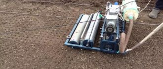
Design, principle of operation and adjustment of the grain seeder SZ-3.6A
For sowing cereals for grain, grain seeders SZ-3.6A, SZ-5.4, SZ-10.8 and their modifications are used to a greater extent.
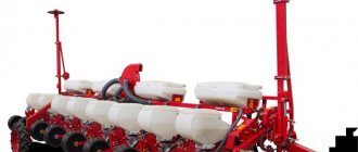
The grain fertilizer seeder SZ-3.6A (Fig. 5) consists of two boxes 1, two sections of sowing devices 17, attached to the bottom of each box, two sections of fertilizer sowing devices 2 installed in the rear wall of the fertilizer compartment of the box, rubber corrugated seed ducts 11, disc coulters 7, 12, harrows 8, two support-drive wheels 3, gear-chain mechanism for driving sowing devices 4, coulter lifting mechanism, hydraulic cylinder 16 and towbar 15.
The box has a partition that divides the box into two compartments: the front one for seeds and the back one for fertilizers. The partition has windows that open and, if necessary, both compartments of the box can be used for filling seeds. The boxes are closed on top with two lids.
Rice. 5. Grain fertilizer seeder SZ-3.6A
a - general view; b - functional diagram; 1 — grain and fertilizer box; 2 — sowing device for fertilizers; 3 — support-drive wheel; 4 — gearbox; 5 — footboard; 6 and 14 - stands; 7 — rear opener; 8 — hider; 9 — compartment for fertilizer box; 10 - tray; 11 - vas deferens; 12 — front opener; 13 - frame; 15 — tow hitch; 16 — hydraulic cylinder; 17 - sowing apparatus and seeds. Each drawer is closed.
The working process . During operation of the seeder, the support-drive wheels 3 rotate the coils for sowing seeds 17 and fertilizers 2. They capture the seeds and fertilizers and feed them into the seed tubes 11. After this, the seeds and fertilizers fall into the coulters 7 and 12 and lie at the bottom of the furrow . The 8 harrows cover seeds and fertilizers at the bottom of the furrow. The working width of the seeder is 3.6 m. The depth of travel of the coulters is 4-8 cm. The capacity of the grain compartment of the box is 453 dm 3, and the fertilizer compartment is 212 dm 3. Operating speed up to 12 km/h. Productivity 3.6 ha/hour.
The working parts of grain seeders are sowing units, coulters and harrows.
Seeding devices are dispensers that select part of the seeds from the seeder box and direct them to the coulters. Their task is to create a uniform and continuous flow of seeds or fertilizers, to ensure the stability of their sowing, regardless of the speed of movement of the sowing unit and the topography of the soil. According to the principle of operation, dispensers for grain seeders can be mechanical, pneumatic and electromagnetic.
Mechanical sowing units are divided into bobbin, bobbin-pin and vibrating. The main ones are of the reel type. They are universal dispensers for sowing grain crops. On modern seeders, reel devices are installed with bottom seeding, and for large-seeded crops (peas, beans, legumes) - with top seeding to reduce the degree of mechanical injury to the seeds.
The main parts of the reel seeder (Fig. 6) include: seed box, reel 1, coupling 9, shaft 4 and spring-loaded valve 6.
Rice. 6. Reel-type sowing devices
a, b - ordinary seeders; c- grass seeders; g, e - vegetable seeders. 10 and 24 - coils; 2 - socket; 19 — body; 4, 11 and 15 - shafts; 5 — coupling rib; 6, 12, 16 — valves; 7 — adjusting bolt; 8 - axis; 9 — coupling; 13 - damper; 14 - fixed bottom; 17 and 22 — springs; 18 - tedder; 20 — disk; 21 - window; 23 - bolt
The seed box is attached to the bottom of the grain box. The coil is fixed to shaft 4 and rotates during operation along with the shaft. At the bottom of the box, a curved valve 6, concave in the middle, is installed on the axis to empty the seed box.
The working process.
Seeds from the grain box are poured into housing 3 of the sowing apparatus. As the coil rotates, the seeds fill its grooves and move to the seed tubes. The number of sowing seeds depends on the length of the working part of the coil and the speed of its rotation, which is regulated by changing the gear ratio of the gear and chain drive. This is achieved by moving gears in the gearbox or changing sprockets in the chain drive. The length of the working part of the coil is set using the seeding regulator lever by moving it to the left or right of the shaft with the coils.
The seeder's sowing units must have the same working length. It is checked using templates and adjusted using compensation washers on the shaft of the apparatus and by moving the seed box relative to the bottom of the box. The deviation of the length of the working part of the coil from the specified length should be + 1 cm. The coils operate without damaging the seeds if the length of its working part is at least twice the maximum size of the seed. Depending on the size of the seed, the gap between the valve and the lower edge of the sowing unit coupling is set: 0-2 mm for cereal grains and 8-10 mm for large-seeded legumes.
Reel-pin devices (Fig. 6b) can also be installed on grain seeders. Their seeding rate is regulated by the rotation speed of the coil and damper 13. For sowing small-seeded crops, replaceable coils with a toothed surface are installed on the shaft of the apparatus, and for large seeds, the kit includes coils with special shoulders with ribs.
Klen grain seeders are equipped with a sowing system with an electric drive and an electronic drive from the cab. It consists of a dispenser, a control panel, a multiplexer and a speed sensor. The dispenser has an electric drive with microprocessor control.
On modern wide-cut seeders and combined units, pneumomechanical sowing devices with centralized seed dosing are installed. The supply of seeds from the hopper is ensured by a reel-type dispenser, and the seeds are transported through pneumatic drives and seed lines by air flow.
Openers are the second main working part of grain seeders. They serve to create a furrow in the soil and place seeds and fertilizers at the bottom. The appearance of uniform, friendly shoots and plant development largely depend on the quality of work of the openers.
The openers must create uniform furrows of a given depth, do not bring the lower layers of soil to the surface of the field so that there is no loss of moisture, compact the bottom of the furrow to renew the capillaries in the soil, ensure uniform distribution of seeds in the furrow, and sprinkle them with a damp layer of soil. The most common types of openers are the double-disc single-row (regular) opener (Fig. 7) and the keel opener (Fig. 8).
Rice. 7. Disc coulters
a – double-disc single-line; b – two-disc two-line; c – double-disc single-line with flanges; d – double-disc double-row with flanges; d – single disk; e – double-disc with disk knife.; 1, 11, 13, 17, 24 – disks; 2 – leash; 3 – rod with a spring; 4 – opener body; 5 and 12 – seed ducts; 6 – bearing; 7 and 10 – disk axes; 8 - cover; 9 – distributor; 14, 25 and 28 – brackets; 15 and 19 – flanges; 16, 20 and 23 – guillemots; 18 and 21 - watering cans; 22 – hub; 26 – disk knife; 27 – suspension; 29 – disc coulter.
A double-disc single-row (regular) opener consists of two flat discs 1, a body 4 with a bell and a driver 2. Shaped covers 8 are attached to the discs, into which axles 7 with bearings 6 are inserted. The edge of the discs cuts the soil and is therefore pointed.
In the front part, the discs converge, forming wedges with an angle of 10º. The gaps between them must be at least 1.5 mm. Two scrapers and a guide plate are attached to the rear of the opener body to guide the seed to the bottom of the furrow. Rubber seals are installed between the body and the disks. When the coulter moves, discs 1 rotate, cut the soil and shift it to both sides, creating a furrow. Seeds and mineral fertilizers fall along the guide plate to the bottom of the furrow. The walls of the furrow crumble and partially cover the seeds and fertilizers with soil. The internal surfaces of the discs are cleaned with scrapers.
Preparing the grain seeder for work
| Reference information Adjustments of agricultural machines |
Grain fertilizer seeder SZ-3.6
The industry produces a family of grain-fertilizer seeders of various modifications. The basic model of the family of trailed seed drills is the SZ-3.6 seeder. It is intended for row sowing of seeds of cereals, legumes, cereals and some other crops with simultaneous application of granular mineral fertilizers into the rows.
Preparing the SZ-3.6 seeder for work includes checking the completeness and correctness of assembly, arranging the openers, installing the sowing devices at a given rate of sowing seeds and fertilizers, as well as installing markers.
Checking completeness and correct assembly.
The seed and fertilizer boxes are checked for cracks and foreign objects. Particular care should be taken to check the seeding devices: the ease of rotation of the shafts, the reliability of fastening the housings of the seeding devices to the box, the working length of the reels and the opening size of the valves. The shafts of the grain sowing devices must move freely in the axial direction using the seeding regulator levers. When the coils are fully pushed into the housings, their ends should be flush with the surface of the sockets. The protrusion of individual coils is eliminated by shifting the casings of the sowing units relative to the coils due to oblong holes for bolts securing the casings to the bottom of the box.
The seed tubes are checked for the absence of plugs from sprouted seeds or random objects. For disc coulters, the freedom of rotation of the discs is checked, as well as the cutting edges, the thickness of which is no more than 0.5 mm.
The cotter pins must be installed in the same hole in the opener rods. The exception is the coulters located opposite the tractor wheels. The pressure of their springs should be greater than the others.
The air pressure in the chambers of the pneumatic support-drive wheels is 0.15…0.20 MPa.
Arrangement of coulters at a given row spacing.
It is best to place the openers on the installation board, on which the middle of the seeder is marked, after placing the board between its wheels and aligning the mark on it with the plumb point of the middle of the seeder. After this, loosen the fastenings of the coulter leads and align the coulters with the marks on the installation board, applied at intervals of 30 cm for the coulters of the front and rear rows.
Installation of devices at a given seeding rate of seeds and fertilizers.
The seeder is installed to determine the seeding rate before leaving for the field. First, the seed sowing rate q (kg) is calculated for a certain number of revolutions of the support-drive wheels (usually 15 revolutions) according to the formula:
where 15 is the accepted number of rotations of the seeder wheel;
Q—specified seeding rate, kg/ha;
πD—wheel rim length, m;
B—seeder working width, m;
α = 1.05 is a coefficient that takes into account wheel slip.
The values of Q, πD and B are selected from the table. 5 as directed by the teacher. The number 2 in the denominator of the formula shows that the calculation is carried out only for half of the seeding units of the seeder.
Checking the actual sowing of seeds is carried out as follows. Using the diagram (Fig. 1), taking into account the given norm, the length of the working part of the coil is determined. For example, the sowing rate for wheat seeds is 170 kg per hectare. This standard may be available under the following conditions (Table 1):
Table 1
| Possible options | Length of the working part of the coil, mm | Gear ratios, i |
| 1 | 22 | 0,616 |
| 2 | 32 | 0,428 |
Rice. 1. Diagram of the dependence of the seed sowing rate on the length of the working part of the reel for various gear ratios i of the SZ-3.6A seeder: P – wheat, R – rye, O – oats, Gr – buckwheat, L – flax.
They strive to ensure that the seeding rate is ensured by the maximum reach of the working part of the reels and the minimum possible gear ratio in the gear scheme. At the same time, the seeds are sown more evenly and are crushed less. In this example, you should choose the second option. Taking into account the recommendations of table. 2 in the gearbox (Fig. 2), using replaceable gears, set the desired gear ratio (in our example i = 0.428).
Rice. 2. Diagram of the gear mechanism in the gearbox of the SZ-3.6A seeder
table 2
Transfer to the shaft of grain machines
| Options | Number of gear teeth | Gear ratio | Planted crop | |||
| D | E | AND | AND | |||
| 1 | 17 | 25 | 17 | 30 | 0,198 | Millet, buckwheat |
| 2 | 25 | 17 | 17 | 30 | 0,428 | Wheat |
| 3 | 17 | 25 | 30 | 17 | 0,616 | Barley |
| 4 | 25 | 17 | 30 | 17 | 1,33 | Oats |
Set the gap between the valve and the lower edge of the sowing unit coupling to 1...2 mm when sowing grain seeds (8...10 mm when sowing legumes) (Fig. 3). Then the seeder frame is jacked up so that one of the wheels can rotate freely. One of the halves of the seed box is filled with seeds, and a tarpaulin is spread under the openers or bags are tied under the seed tubes. The drive wheel is turned 2…3 times so that the sowing units are filled with seeds. The spilled seeds are collected and poured back into the seed box. The tarpaulin is spread again under the openers. Make a mark on the support wheel (preferably with chalk) and rotate it 15 times with a frequency approximately corresponding to the speed of movement of the unit when sowing (about 40 revolutions per minute). The sown seeds are collected and weighed to the nearest 1 gram. The resulting mass is compared with the calculated mass determined by formula (1). If the discrepancy with the calculated value does not exceed ± 3%, then we can assume that the seeder is correctly set to the specified seed sowing rate. If a larger or smaller mass of seeds spilled onto the tarpaulin, then the regulator must be used to respectively reduce or increase the working length of the coils and repeat the experiment. After checking, the regulator lever is secured in the installed position.
Rice. 3. Setting gaps
The second half of the seeder is set to the seeding rate in a similar way. You can make a template along the length of the working part of the coil of the first half of the seeder. This template is used when checking the seed sowing rate with seeders in the field.
The fertilizer sowing devices of grain-fertilizer row seeders have coils with pins that are not moved in the axial direction, so the amount of fertilizer sown is determined only by the speed of rotation of the coils. The seeding rate of fertilizers can be slightly adjusted by changing the cross-sections of the outlet windows (latches) in the rear wall of the box. By changing gears A, B, C and D (Table 3), you can get six gear ratios that ensure sowing from 36 to 235 kg/ha of granular superphosphate. When sowing fertilizers of normal humidity, the gap between the pins of the reels and the valves is set using the levers for emptying the boxes to be equal to 8...10 mm.
Table 3
Transfer to the shaft of fertilizer machines
| Installation | Number of gear teeth | Installation Center | Gear ratio | Approximate seeding rate of granular superphosphate, kg/ha | |||
| A | B | IN | G | ||||
| I | 15 | 36 | 15 | 30 | O1 | 0,067 | 36…38 |
| 2 | 15 | 36 | 25 | 30 | O2 | 0,112 | 61….67 |
| 3 | 15 | 36 | 30 | 25 | O2 | 0,160 | 86…95 |
| 4 | 36 | 25 | 15 | 30 | O3 | 0,232 | 128…143 |
| 5 | 15 | 36 | 30 | 15 | O1 | 0,268 | 133… 163 |
| 6 | 36 | 15 | 15 | 30 | O1 | 0,386 | 199. ..235 |
The method for setting the seeder to a given seeding rate for fertilizers is the same as for seeds. The seeder is considered to be set to the specified fertilizer seeding rate if the actual seeding differs from the norm by no more than 10%.
Operation of the seeder and its adjustment in the field.
Preparing the field for sowing includes choosing the method of movement of the unit, cutting out headlands, dividing the field into paddocks and setting the line for the first pass.
Sowing should be carried out across the direction of plowing and the last pre-sowing tillage or at an angle to them. On the first passes, the seeding rate is adjusted. To do this, seeds are poured into the seed box in an even layer 5...8 cm from the bottom and their level is marked with a line on the wall (chalk). Calculation determines the seed consumption (kg) for two passes of the unit (control sample) using the formula:
where L is the length of the run, m (can be taken 30...50 m);
В – working width of the seeder, m;
Q – seed sowing rate, kg/ha.
Pour the control portion into the seed box of the seeder, level the seeds and, after two passes along the mark on the wall of the seed box, check how many seeds of the control portion have been consumed. If necessary, adjust the seeding rate using the regulator lever and then repeat the check.
The depth of travel of the coulters is adjusted using the depth regulator screw located on the nose of the seeder. The openers will be as deep as possible when the screw is fully tightened.
Compilation of the unit.
Seeders SZ-3.6 are connected in echelon, and SZP-3.6 in rank. In an echeloned unit, machines are connected in two rows to the hitch: the first row is directly to the hitch beam, the second is to the extensions. The row arrangement of machines allows for better stability of the butt spacing between adjacent machines, reduces the exit length and increases the maneuverability of the unit. The hitch bars are attached at the attachment points of the seeders and adjusted so that when they are tensioned, all the hitch bars form one straight line.
Attach the seeders to the hitch or hitch extension, selecting the required hole on the seeder trailer so that in the working position the bottom of the seed box is horizontal.
To loosen the soil along the tracks of tractors K-701, T-150K, T-150, etc., harrows and a chain are attached to the hitch.
Establishing marker overhang.
A single-seeder unit is equipped with track indicators, an aggregate of two and three seeders is equipped with left and right markers, and wide-cut units are equipped with markers and track indicators. When working with track indicators, the load plumbs should follow the track of the seeder wheel left by the previous pass.
The reach of the left (Lp) or right (Ll) marker, that is, the distance from the outer coulter to the marker tap, is determined by the formula:
where Vagr is the working width of the unit, m;
bm – row spacing, m;
c – the distance between the centers of the front wheels of the tractor (track) or the distance between the inner edges of the tracks, m.
If the unit is driven along the track of the marker using the sighting device, then the departure of the markers is determined using the formula:
where Lc is the distance from the center line of the tractor to the sighting device (right and left), m.
Sources:
Mechanization of agricultural production: Program and guidelines for the educational practice of students of agronomic specialties in the section “Agricultural machines” / Compiled by: A.A. Prokhorov, Yu.A. Ivanov, S.A. Preymak, A.K. Khailov, Yu. M. Grishin, V.N. Nikitin; Federal State Educational Institution of Higher Professional Education "Saratov State Agrarian University". Saratov, 2003
Ormanji K.S. and others. Rules for the production of mechanized work in field farming. M.: Rosselkhozizdat, 1983.
Print date: March 06, 2022
Universal grain seeder SZ-3.6 - adjustment and configuration
Seeder Grain 3.6 meters of grip (SZ-3.6) is a basic, long-proven and widely used model. Used for row sowing of grains (wheat, rye, barley, oats), legumes (peas, beans, chickpeas, soybeans, lentils, lupine) and other crops of similar size and seeding rate (buckwheat, sorghum and others).
A single seeder works with machines of a traction class of 0.9 or 1.4, if several at the same time, more powerful machines are used: 3 class with 3 in the coupling or 5 when connecting 5 SZ-3.6.
Universal seeder for line sowing of seeds SZ-3.6
Owners of land plots who rent it out, farmers and farm managers may be interested in finding out the technical characteristics and what performance indicators are endowed with the basic grain seeder SZ-3.6.
In the article you can get acquainted with the opinions of the owners of the universal product and find out the prices for a new seeder and a used version.
Purpose of the seeder
Performs work on line sowing of seeds such as:
- food and feed wheat;
- food and technical barley;
- oats;
- rye.
Leguminous crops such as:
- chickpeas;
- lupine;
- peas;
- beans.
The universal grain seeder SZ-3.6 photo, which can be seen at the end of the article, is also used for introducing other crops into the soil. In terms of their size and approved seeding rates, they must be suitable and close to grain. This could be: buckwheat, red and yellow millet, white sorghum. This is not the final list of crops that the SZ-3.6 seeder can serve.
The seeder is aggregated with tractors whose traction class indicators are 900 -1400 kg.
| Grain seeder SZ-3.6 technical characteristics | |||||
| 1 | Working width | 3,6 | meters | ||
| 2 | Row spacing | 150 | millimeters | ||
| 3 | Maximum operating speed | 12 | km/hour | ||
| 4 | Highest performance | 4,3 | ha/hour | ||
| 5 | Type | Tow hitch | |||
Let's look at the performance figures given in the table below.
Performance indicators
Manual precision seed drill: characteristics, operating methods.
Read what a lawn seeder is here.
Zil 131 technical specifications, wiring diagram.
Grain seeder SZ-3.6 owner reviews
Excellent and reliable technology in all respects. Summarizing the opinion of the owners, we can say that they RECOMMEND storing the seeder under a canopy. Since the devices responsible for seeding are made of plastic and have a negative attitude towards sunlight. It is recommended to purchase the seeding device together with the unit. It is believed that the sowing quality of the model we are considering is good. No great. The seeds do not bunch up, but are distributed evenly. I like the possibility of additional adjustment of seeding and rate.
Grain seeder SZ-3.6 product price
In Belgorod it can be purchased for 280,000.00 rubles. Depending on the modification, additional equipment, year of manufacture and technical condition, the price may vary. Therefore, you need to constantly keep your finger on the pulse and closely monitor the market. The average cost of a model on the Russian market is 265,000.00 rubles.
Sowing complex Agromaster: description, modifications and advantages.
The Kuzbass sowing complex is here.
Read this article on how to prepare for sowing vegetables with a manual precision seeder.
Eventually
What can we say about the seeder? Perhaps there are more positive aspects than dissatisfied reviews. The design is simple and convenient. A big plus is the ability to independently adjust seeding rates. Convenient hopper for seed and fertilizer. Although many consider the use of plastic parts to be unacceptable and a wrong decision by manufacturers.
Design and operation of the SZ-3.6 seeder
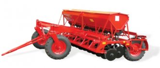
The SZ-3.6 seeder consists of a frame with a trailing device, support-motor wheels, two grain-fertilizer boxes, seed and fertilizer sowing devices, coulters (24), and harrows. It houses a mechanism for transmitting movement from the wheels to the seeding units, and there is a footboard at the back. The kit includes a hydraulic cylinder. It may also include an electronic device for seeding control, which provides an audible and light signal to the tractor driver in case of operational problems.
Seeds are poured into boxes made of sheet steel with a volume of 453 dm2, fertilizers into a fertilizer box with a capacity of 212 dm2. The boxes have closed windows. By removing the dampers, the total capacity is obtained.
1) Bunker - 2 pcs.; 2) Seeding device - 24 pcs.; 3) Fertilizer sowing apparatus - 24 pcs.; 4) Semyatuk pipeline — 24 pcs.; 5) Disc coulter - 24 pcs.; 6) Hiller - 25 pcs.; 7) Train (chain or 6 light seed harrows); Support wheel - 2 pcs.; 9) Drive mechanism; 10) Opener lifting mechanism; 11) Tow hitch; 12) Footboard with handrail; 13) Frame; 14) Marker - 2 pcs.
The seeds fall down by gravity, where the seed sowing machines work, and in the fertilizer box there are fertilizer sowing machines. The movement of their shafts through the transmission system is caused by the rotation of the seeder wheel. The captured grain is thrown out at the seed tube, which are:
- rubber (a) - cheap and light, but relatively short-lived, afraid of frost and sunlight;
- corrugated rubber (b) – bends well and holds volume;
- spiral-tape (c) - made of a long twisted metal strip;
- funnel (d) - a series of funnels lowered into each other, connected by chains. Commonly used for fertilizer;
- spiral wire (d) is made from wire. Good, but heavy, can stretch.
Through the seed tubes, the grain enters the coulters, which, when the unit moves, go deep into the soil to a given depth and place the seeds there. The design of the openers is as follows:
- Anchor . A tip is driven into the ground - a small tip set at an acute angle, to which is attached a tube with seeds spilling out. The design is very simple, but it works well only on structured, well-cultivated fields with normal humidity, without crop residues and weeds.
- Keeled . Similar to an anchor, but the tip is keeled, with an obtuse entry angle. The furrow made has a compacted surface, which favors the rise of moisture through the capillaries to the placed seed (agronomists talk about a “hard bed”). Ideal, but the field must, as in the previous case, be well developed.
- Tubular . A tube with a small cap, they are always attached to the seeder in a hinged and elastic manner. During operation, they easily move up and down, which makes it difficult to maintain the seeding depth, but the coulter is self-cleaning and can work on stubble or almost any field, no matter how clogged.
- Paws . A pointed paw, like a cultivator, to which a sowing tube is attached. At the same time as the sowing plant, it trims weeds and fluffs up the soil. Used for sowing on stubble. It comes in two modifications, for row and rowless sowing. In the second case, a device consisting of a riser and a half-cone is introduced into the design, placed in the lower, rear part of the opener, scattering the seeds throughout the entire furrow made.
- Single disk . The disk is riveted to a cast iron machine with a pressed bearing; in operation it rotates at an angle of attack of 8˚ and a roll angle of 20˚. A scraper is attached to the bottom to clean the disc from soil and prevent the furrow from filling up too early. Used on both treated and untreated fields, preserving stubble in areas with wind erosion.
- Double-disc . Similar to the previous one, but has two disks rotating at an angle of 10˚ to each other. There are double-row double-disc coulters, the angle is blunter, 18˚, and the flow of seeds in them is divided into two jets by a special separator, each one is placed in the wake of its own disc. The most complex in design, heavy, increase the traction force on the tractor, but allow for high-quality sowing and accurately maintain depth in any field.
The seed sowing rate is regulated by what and how exactly on the SZ-3.6 seeder?
Why did they think to ask your question on the resource, but not in the Google search bar? What is this, laziness or incompetence? I simply copied the material without reading it. Find out for yourself.
Grain fertilizer seeder SZ-3.6 Adjustment of seeding rate.
The industry produces a family of grain-fertilizer seeders of various modifications. The basic model of the family of trailed seed drills is the SZ-3.6 seeder. It is intended for row sowing of seeds of cereals, legumes, cereals and some other crops with simultaneous application of granular mineral fertilizers into the rows.
Preparing the SZ-3.6 seeder for work includes checking the completeness and correctness of assembly, arranging the openers, installing the sowing devices at a given rate of sowing seeds and fertilizers, as well as installing markers.
Checking completeness and correct assembly.
The seed and fertilizer boxes are checked for cracks and foreign objects. Particular care should be taken to check the seeding devices: the ease of rotation of the shafts, the reliability of fastening the housings of the seeding devices to the box, the working length of the reels and the opening size of the valves. The shafts of the grain sowing devices must move freely in the axial direction using the seeding regulator levers. When the coils are fully pushed into the housings, their ends should be flush with the surface of the sockets. The protrusion of individual coils is eliminated by shifting the casings of the sowing units relative to the coils due to oblong holes for bolts securing the casings to the bottom of the box.
The seed tubes are checked for the absence of plugs from sprouted seeds or random objects. For disc coulters, the freedom of rotation of the discs is checked, as well as the cutting edges, the thickness of which is no more than 0.5 mm.
The cotter pins must be installed in the same hole in the opener rods. The exception is the coulters located opposite the tractor wheels. The pressure of their springs should be greater than the others.
The air pressure in the chambers of the pneumatic support-drive wheels is 0.15…0.20 MPa.
Arrangement of coulters at a given row spacing.
It is best to place the openers on the installation board, on which the middle of the seeder is marked, after placing the board between its wheels and aligning the mark on it with the plumb point of the middle of the seeder. After this, loosen the fastenings of the coulter leads and align the coulters with the marks on the installation board, applied at intervals of 30 cm for the coulters of the front and rear rows.
Installation of devices at a given seeding rate of seeds and fertilizers.
The seeder is installed to determine the seeding rate before leaving for the field. First, the seed sowing rate q (kg) is calculated for a certain number of revolutions of the support-drive wheels (usually 15 revolutions) according to the formula:
where 15 is the accepted number of rotations of the seeder wheel; Q—specified seeding rate, kg/ha; π—wheel rim length, m;
B—seeder working width, m;
a = 1.05 is a coefficient that takes into account wheel slip.
The values of Q, π and B are selected from the table. 5 as directed by the teacher. The number 2 in the denominator of the formula shows that the calculation is carried out only for half of the seeding units of the seeder.
Checking the actual sowing of seeds is carried out as follows. Using the diagram (Fig. 1), taking into account the given norm, the length of the working part of the coil is determined. For example, the sowing rate for wheat seeds is 170 kg per hectare. This standard may be available under the following conditions (Table 1):
They strive to ensure that the seeding rate is ensured by the maximum reach of the working part of the reels and the minimum possible gear ratio in the gear scheme. At the same time, the seeds are sown more evenly and are crushed less. In this example, you should choose the second option. Taking into account the recommendations of table. 2 in the gearbox (Fig. 2), using replaceable gears, set the desired gear ratio (in our example i = 0.428).
Set the gap between the valve and the lower edge of the sowing unit coupling to 1...2 mm when sowing grain seeds (8.10 mm when sowing legumes) (Fig. 3). Then the seeder frame is jacked up so that one of the wheels can rotate freely. One of the halves of the seed box is filled with seeds, and a tarpaulin is spread under the openers or bags are tied under the seed tubes. The drive wheel is rotated 2.3 times to fill the sowing units with seeds.
The spilled seeds are collected and poured back into the seed box. The tarpaulin is spread again under the openers. Make a mark on the support wheel (preferably with chalk) and rotate it 15 times with a frequency approximately corresponding to the speed of movement of the unit when sowing (about 40 revolutions per minute). The sown seeds are collected and weighed to the nearest 1 gram. The resulting mass is compared with the calculated mass determined by formula (1). If the discrepancy with the calculated value does not exceed ± 3%, then we can assume that the seeder is correctly set to the specified seed sowing rate. If a larger or smaller mass of seeds spilled onto the tarpaulin, then the regulator must be used to respectively reduce or increase the working length of the coils and repeat the experiment. After checking, the regulator lever is secured in the installed position.
The second half of the seeder is set to the seeding rate in a similar way. You can make a template along the length of the working part of the coil of the first half of the seeder. This template is used when checking the seed sowing rate with seeders in the field.
The fertilizer sowing devices of grain-fertilizer row seeders have coils with pins that are not moved in the axial direction, so the amount of fertilizer sown is determined only by the speed of rotation of the coils. The seeding rate of fertilizers can be slightly adjusted by changing the cross-sections of the outlet windows (latches) in the rear wall of the box. By changing gears A, B, C and D (Table 3), you can get six gear ratios that ensure sowing from 36 to 235 kg/ha of granular superphosphate. When sowing fertilizers of normal humidity, the gap between the pins of the reels and the valves is set using the levers for emptying the boxes to be equal to 8...10 mm.
The method for setting the seeder to a given seeding rate for fertilizers is the same as for seeds. The seeder is considered to be set to the specified fertilizer seeding rate if the actual seeding differs from the norm by no more than 10%.
Operation of the seeder and its adjustment in the field. Preparing the field for sowing includes choosing the method of movement of the unit, cutting out headlands, dividing the field into paddocks and setting the line for the first pass.
Sowing should be carried out across the direction of plowing and the last pre-sowing tillage
or at an angle to them. On the first passes, the seeding rate is adjusted. To do this, seeds are poured into the seed box in an even layer 5...8 cm from the bottom and their level is marked with a line on the wall (chalk). Calculation determines the seed consumption (kg) for two passes of the unit (control sample) using the formula:
where L is the length of the run, m (can be taken 30...50 m);
B—seeder working width, m;
Q—seed sowing rate, kg/ha.
Pour the control portion into the seed box of the seeder, level the seeds and, after two passes along the mark on the wall of the seed box, check how many seeds of the control portion have been consumed. If necessary, adjust the seeding rate using the regulator lever and then repeat the check.
The depth of travel of the coulters is adjusted using the depth regulator screw located on the nose of the seeder. The openers will be as deep as possible when the screw is fully tightened.
Compilation of the unit.
Seeders SZ-3.6 are connected in echelon, and SZP-3.6 in rank. In an echeloned unit, machines are connected in two rows to the hitch: the first row is directly to the hitch beam, the second is to the extensions. The row arrangement of machines allows for better stability of the butt spacing between adjacent machines, reduces the exit length and increases the maneuverability of the unit. The hitch bars are attached at the attachment points of the seeders and adjusted so that when they are tensioned, all the hitch bars form one straight line.
Attach the seeders to the hitch or hitch extension, selecting the required hole on the seeder trailer so that in the working position the bottom of the seed box is horizontal.
To loosen the soil along the tracks of tractors K-701, T-150K, T-150, etc., harrows and a chain are attached to the hitch.
Establishing marker overhang.
A single-seeder unit is equipped with track indicators, an aggregate of two and three seeders is equipped with left and right markers, and wide-cut units are equipped with markers and track indicators. When working with track indicators, the load plumbs should follow the track of the seeder wheel left by the previous pass.
The reach of the left (Lp) or right (Ll) marker, that is, the distance from the outer coulter to the marker tap, is determined by the formula:
where Vagr is the working width of the unit, m;
bm—row spacing, m;
с is the distance between the centers of the front wheels of the tractor (track) or the distance between the inner edges of the tracks, m.
If the unit is driven along the track of the marker using the sighting device, then the departure of the markers is determined using the formula:
where Cs is the distance from the center line of the tractor to the sighting device (right and left), m.
G - peas; Gr - buckwheat: L - flax; O - oats; P - wheat; R - rye.
The gear ratio i=0.428 is set using replaceable gears. Having determined the length of the working part of the coil from the diagram, set it with a lever on each half of the seeder.
Since this setting is approximate, you need to check the seeding rate before going into the field. The seeder is jacked up like this. so that the supporting water wheel rotates freely, a tarpaulin is laid under the coulters, and seeds are poured into the box at least half the container. The wheels are turned several times so that the seeds completely fill all sowing devices and begin to fall out (that is, a steady state has begun). The spilled seeds are picked up and then each wheel is evenly rotated 20 revolutions
The seeds spilled onto the tarpaulin from all coulters are weighed and the mass of seeds the seeder should sow in 20 revolutions of the running wheels at a given seeding rate is calculated, as follows. It is known that the support on the drive pneumatic wheel of the seeder is 9.5/9-32 with an air pressure inside the chambers of 0.16. . .0.20 MPa has a rim length (taking into account tire deflection) of 3.67 m and the working width of the seeder is 3.6 m. Therefore, in one revolution of the wheels the seeder will sow an area of 3.67 × 3.6 = 13.2 m2, and in 20 revolutions - 13.2 × 20- 264 m2. With a seeding rate of 170 kg/ha per 1 m2, 170/10000=0.017 kg should be sown. or 17 g of seeds, and on an area of 264 m2 you need to sow 17×264 = 4488 g or 4.488 kg. It is allowed to exceed the seeding rate from the calculated value to 5% (taking into account wheel slip in the field). Therefore, in our example, the seeder should sow seeds in the range from 4.488 to 4.670 kg in 20 wheel revolutions. If only one half of the seeder will sow, the result obtained should be divided in half.
If a large mass of seeds is poured onto the tarpaulin, you should use the regulator to reduce the working length of the reels and again spin the wheels 20 revolutions until the calculated amount of seeds is sown
The actual seeding rate in the field is checked on the area sown with a certain number of seeds. The approximate mass of sown seeds can be checked on an area of 0.02 hectares when sowing which the SZ-3.6 seeder (and its modifications with the same sizes of running wheels) will make 14.7 revolutions of the running wheels (taking into account 3% of their slip). Therefore, in the considered example, the C3-3.6 seeder at a rate of 170 kg/gas and 14.7 wheel revolutions should sow 3.4 kg of seeds, pre-weighed and poured into the seed box. If the box contains 34 kg. then they must be sown on an area of 0.2 hectares, which is a path of 555 m for one pass of one seeder. After checking, the regulator levers are secured in the installed position.
The seeding rate of fertilizers. Grain seeders of the SZ series are set approximately at the seeding rate of granulated superphosphate according to the table. First, the fertilizer emptying levers are moved to the uppermost position. The valves of all fertilizer sowing devices must touch the pins of the reels. To do this, you need to unscrew the locking bolts, move the valves until they come into contact with the coil pins and secure. Then the emptying levers are turned like this. so that there is a gap of 8. between the pins of the Reels and the valves of each fertilizer sowing device. .10 mm. With such a gap, fertilizers of normal humidity (no more than 6%) are sown. If the humidity is high and fertilizers are poorly sown, then the valves are lowered slightly. The fertilizer seeding rate can be slightly adjusted by changing the size of the exit windows in the rear walls of the box using valves.
Finally, the seeding rate of fertilizers is checked by turning the support-drive wheels on the site or during test seeding in the same way as for grain sowing devices
8 Technological adjustments, preparation for work.
Before leaving for the field, they check the completeness and serviceability of each seeder. The mating gears of the gear train must be located in the same plane. Axial displacement in the working position is allowed up to 2 mm. The gap between the tops of the teeth and the cavities of the mating gears should not exceed 2 2.5 mm. Sprockets covered by one chain must be located in the same plane. Chain misalignment should not exceed 2 mm. The chain is tensioned like this. so that when pressing on a non-working branch with a force of 100 N (approximately 10 kgf), it bends by 10... 15 mm. Hook chains are put on the sprockets with the hooks up and forward in the direction of movement.
Uniformity of seeding Grain sowing devices are adjusted for uniformity of seeding as follows: The control levers are moved to the extreme (zero) position. In this case, the ends of the coils of all sowing devices must be flush with the inner plane of the sockets. In devices whose coils protrude or recess more than 0.5 mm. it is necessary to loosen the bolts securing the case to the box and move it (due to the holes) like this. so that the end of the coil is flush with the socket. Then check the installation of the valves.
Seed sowing rate. We will consider setting the grain seeder to a given seed sowing rate before going into the field using the example of the C3-3.6 seeder. Using the diagram, taking into account the given seeding rate, we determine the gear ratio /. In this case, you should strive to take a longer working length of the coil. For example, the sowing rate for wheat seeds is set to 170 kg/ha. On the vertical scale we find 170 and draw a horizontal line (shown by arrows) until the intersection of the inclined lines P|=0.616 and ni=o.428 0t intersection points, draw vertical lines down and get the length of the working part coils are 22 and 32 mm, respectively. It is better to take a length of 32 mm. since in this case the seeds are sown more evenly and are crushed less.
Grain seeding rate for seeder sz-3.6, table, graph
Seeder modifications
Grain seeder SZ-3.6 – basic model. The changes made to the design change the sowing conditions, price, and ease of use. Distributed SZ-3.6A. The differences of this model are as follows.
- It has a USK (unified control system) and is supplied only with it. If the seeds do not pour out into any coulter or when the level of grain (fertilizer) drops below a certain limit, it gives a signal to the tractor driver.
- Instead of a gear transmission in the SZ-3.6, the SZ-3.6A has two small-sized gearboxes; adjustment is more convenient, without removing the casing and replacing gears.
- Additionally, a sampler is installed on 3 right (in the direction of travel) coulters, which is used when adjusting the seeding rate.
- A device has been installed to block the seeding of seeds in coulters moving along the tramline. Instead of serrated hooks, there are tip hooks.
- Ears are attached to the foot board at the bottom, where you can attach the chains of seeding harrows.
- The drive shaft of the seed seeding coils has been changed from round to square.
If necessary, any SZ-3.6 seeder can be changed by installing, for example, coulters of a different design instead of the basic ones. It all depends on the crop being sown and working conditions (field preparation). Thus, in NWT-3.6, intended for subsurface sowing of grasses, there are fewer reels, since the seeds are smaller. And since they are also less flowable, an additional stirrer is installed in the box to help ensure an even flow of seeds.
Technological adjustments of seeders and preparation for work in the field
8. Technological adjustments and preparation for work
Before leaving for the field, they check the completeness and serviceability of each seeder. The mating gears of the gear train must be located in the same plane. Axial displacement in working position is allowed up to 2 mm. The gap between the tops of the teeth and the valleys of the mating gears should not exceed 2. .2.5 mm. Sprockets covered by one chain must be located in the same plane. The chain misalignment should not exceed 2 mm. The chain is tensioned so that when the non-working branch is pressed with a force of 100 N (approximately 10 kgf), it bends by 10. .15 mm. Hook chains are put on the sprockets with the hooks up and forward in the direction of movement.
Seeding uniformity
.
Grain sowing devices are adjusted for seeding uniformity as follows. The control levers are moved to the extreme (zero) position. In this case, the ends of the coils of all sowing devices must be flush with the inner plane of the sockets .
In devices whose coils protrude or recess more than 0.5 mm, it is necessary to loosen the bolts securing the housing to the box and move (due to the holes) so that the end of the coil is flush with the socket.
Then check the installation of the valves .
Seed sowing rate.
We will consider setting a grain seeder to a given seed sowing rate before going into the field using the example of the SZ-3.6 seeder.
Using the diagram, taking into account the given seeding rate, we determine the gear ratio i .
In this case, you should strive to take a longer working length of the coil. For example, the sowing rate for wheat seeds is set to 170 kg/ha. On the vertical scale we find 170 and draw a horizontal line (shown by arrows) until the intersection of the inclined lines Pi=0.616 and Pi=0.428. From the intersection points we draw vertical lines down and obtain the length of the working part of the coil, respectively 22 and 32 mm. It is better to take a length of 32 mm, since in this case the seeds are sown more evenly and are crushed less.
Figure 4. Diagram of the approximate dependence of the seeding rate on the length L
the working part of the coil at various gear ratios for seeders SZ-3.6, SZL-3.6, SZL-3.6, SZU-3.6, SLT-3.6
and
SZO-3.6:
G - peas; Gr —
buckwheat;
L -
flax;
O - oats; P
- wheat;
R -
rye.
The gear ratio i=0.428 is set using replaceable gears. Having determined the length of the working part of the coil from the diagram, set it with a lever on each half of the seeder.
Since this setting is approximate, you need to check the seeding rate before going into the field. The seeder is jacked up so that the support water wheel rotates freely, a tarpaulin is placed under the coulters, and seeds are poured into the box at least half the container. The wheels are turned several times so that the seeds completely fill all sowing devices and begin to fall out (that is, a steady state has begun). The spilled seeds are picked up and then each wheel is evenly rotated 20 revolutions.
The seeds spilled onto the tarpaulin from all openers are weighed and the mass of seeds that the seeder should sow in 20 revolutions of the running wheels at a given seeding rate is calculated as follows. It is known that the support on the drive pneumatic wheel of the seeder is 9.5/9-32 at an air pressure inside the chambers of 0.16. . .0.20 MPa has a rim length (taking into account tire deflection) of 3.67 m, and the working width of the seeder is 3.6 m. Therefore, in one revolution of the wheels the seeder will sow an area of 3.67 × 3.6 = 13.2 m2, and for 20 revolutions - 13.2 × 20-264 m2. With a seeding rate of 170 kg/ha per 1 m2, 170/10000 = 0.017 kg, or 17 g of seeds should be sown, and on an area of 264 m2, 17 × 264 = 4488 g, or 4.488 kg should be sown. It is allowed to exceed the seeding rate from the calculated value to 5% (taking into account wheel slip in the field). Therefore, in our example, the seeder should sow seeds in the range from 4.488 to 4.670 kg in 20 wheel revolutions. If only one half of the seeder will sow, the result obtained should be divided in half.
If a large mass of seeds is poured onto the tarpaulin, you should use the regulator to reduce the working length of the reels and again spin the wheels 20 revolutions until the calculated amount of seeds is sown.
The actual seeding rate in the field is checked on the area sown with a certain number of seeds. The approximate mass of sown seeds can be checked on an area of 0.02 hectares, when sowing which the SZ-3.6 seeder (and its modifications with the same sizes of running wheels) will make 14.7 revolutions of the running wheels (taking into account 3% of their slip). Consequently, in the considered example, the SZ-3.6 seeder at a rate of 170 kg/gas and 14.7 wheel revolutions should sow 3.4 kg of seeds, pre-weighed and poured into the seed box. If 34 kg are poured into a box, then they must be sown on an area of 0.2 hectares, which is a path of 555 m for one pass of one seeder. After checking, the regulator levers are secured in the installed position.
Fertilizer seeding rate
.
Grain seeders of the SZ series are set approximately at the seeding rate of granular superphosphate according to the table .
First, the fertilizer emptying levers are moved to the uppermost position. The valves of all fertilizer sowing devices must touch the pins of the reels. To do this, you need to unscrew the locking bolts, move the valves until they come into contact with the coil pins and secure. Then the emptying levers are turned so that there is a gap of 8. between the pins of the Reels and the valves of each fertilizer dispenser. .10 mm. With such a gap, fertilizers of normal humidity (no more than 6%) are sown. If the humidity is high and fertilizers are poorly sown, then the valves are lowered somewhat. The fertilizer seeding rate can be slightly adjusted by changing the size of the exit windows in the rear walls of the box using valves.
Finally, the seeding rate of fertilizers is checked by turning the support-drive wheels on the site or during test seeding in the same way as for grain sowing devices.
Depth of seed placement in the soil
regulated by changing the depth of travel of the coulters.
Opener placement
. The coulters are placed at specified row spacings on a marking board. In grain seeders, the distance between the center lines of adjacent coulters should be 15 cm. Before leaving for the field, check the serviceability and correct installation of the guides and scrapers of double-disc coulters (except for the SZU-3.6 seeder). The guide should deliver the seeds to the bottom of the open furrow. The discs must rotate freely and have a blade thickness of no more than 0.5 mm. Spring harrows in SZ-3.6 seeders are installed in the row spacing of the coulters, and in SZU-3.6 seeders so that the harrow tooth is located behind each disk of the front coulters.
In the SZ-3.6 seeder and others of this series, the correct operation of the hydraulic drive is checked. During operation, the tractor hydraulic system distributor handle must be in the neutral position.
The depth of travel of the anchor coulters is adjusted by installing or removing additional weights.
Preparation for work, adjustment to a given seeding rate
First, the completeness and technical condition are checked. The drive chains must be installed correctly - with the hooks up and forward in the direction of travel, check the operation of the drive mechanisms of the seeding units, clean the boxes, and lubricate them.
They install the USC and check the work.
Attention: when connecting, observe polarity to avoid damage!
The location of the openers in accordance with the specified sowing pattern is checked using a special board with marks. The board is laid down and, if the positions of the openers do not coincide with the marks, they are moved to the required places where they are fixed.
- Setting the seeder to the seeding rate is done on the installed unit.
- Place it on the trestle so that you can turn the wheels manually (they should not touch the ground).
- Move the regulator, checking whether all coils have the same length of the working part. Move if necessary.
- Check the gap between the valve planes and the lower rib of the coupling. It should not be more than 2 mm when sowing grains or 8-10 mm when sowing large legumes.
- Calculate the gear ratio. Use the diagram from the instruction manual. The selection is made based on the minimum gear ratio and the maximum extension of the working part of the coils.
- The seeds are poured into boxes and a tarpaulin is placed under the openers. Or they put bags on the vas deferens. The gears are installed to the mechanism for transmitting movement from the wheel to the shafts of the sowing devices.
- Turn the wheel several times to fill the coils. The spilled grain is picked up and returned back to the box.
- Turn the wheel 15 times at a speed comparable to movement in the field (the seeder is designed for an operating speed of no higher than 4.2 m/s).
The spilled grain is weighed and the seeding rate is checked using the formula: K=15πDVN/(10,000∙2(1-K))
Where K is the number of seeds per 15 revolutions, kg; D – wheel rim diameter, m; В – working width, m; required seeding rate, kg/ha; “2” – is entered when calculating for seeders in which half of the sowing units operate from the wheel; if everything is from 1 wheel, the number “2” is not entered into the formula; K – wheel slip coefficient, approximately equal (depending on the condition of the soil and how “bald” the tire is) 0.03–0.1.
If you are going to sow low-flowing grass seeds, it is better to turn the wheel 30 times; accordingly, instead of “15”, enter “30” into the formula - the result will be more accurate.
The adjustment is completed by setting the marker offset and placing the trail indicator.
Technological adjustment of seeders type SZ-3, 6
Technological adjustment of seeders type SZ-3.6.
Checking the technical condition of seeders.
Before sowing, check the technical condition of the working parts. The coulter discs must rotate freely. The gap between them at the point of contact is no more than 1.5 mm, the thickness of the blade is no more than 0.5 mm, the width of the sharpening chamfer is 6...7 mm.
It is prohibited to work without scrapers and seed guides. The coulter leads must be straight, and the length of the pressure springs in the free state must be the same for all coulters. There should be no breaks in the seed tubes. The coils of the seeding devices must rotate freely together with the sockets, and the shaft together with the coils must move in the housings when the seeding regulator lever is moved by hand.
When setting up the seeders technologically, the coulters are set to the specified row spacing and seed placement depth, the sowing devices are adjusted for uniformity and seeding rate, and the offsets of markers and track indicators are set.
Setting the coulters to the row spacing.
When setting the coulters to the row spacing, use a marking board on which lines are drawn at a distance equal to the specified row spacing. The openers are lowered onto the marking board and, loosening the fastenings of the leads, the discs are aligned with the corresponding mark on the board. The placement of the coulters begins from the middle of the marking board.
Setting the depth of the coulters.
Before leaving for the field, the transport clearance is checked and, if necessary, adjusted using the rotation screws of the square axis of the coulter mounting, i.e. distance from the bottom point of the coulters in transport position to the road. For seeders of the SZ-3.6 family, the clearance must be at least 150 mm.
Measure the pressure in the tires and bring it to normal (0.16...0.20 MPa). Different pressures in the tires of the wheels of one seeder are not allowed.
The depth of planting seeds into the soil depends on the depth of travel of the coulters, which is adjusted with the depth regulator screw located on the rear of the seeder. The maximum depth is achieved when the screw is fully screwed in, the minimum (about 4 cm) when it is unscrewed (the hydraulic cylinder rod must be fully retracted.
To ensure uniform deepening of the openers, the springs of all openers are compressed equally. If the coulters following the tractor wheel tracks do not go deep to the specified depth, it is necessary to tighten the springs on the rods of the corresponding coulters. In order to ensure uniform depth of travel of the coulters, cultivator paws can be additionally installed on the seeder frame to loosen the soil compacted by the wheels of the tractor, as well as by the wheels of the seeder.
Installation of seeding devices for seeding uniformity.
To ensure uniformity of seeding, all sowing device coils must be positioned equally relative to their housings, which is achieved by moving the housings in oval holes. This will allow you to set the same working length of the coils when moving them with one regulator lever.
As already noted, the gap between the valve and the coupling rib on all sowing devices should be the same and amount to 1...2 mm when sowing grain and 8...10 mm for peas and other large-seeded crops.
When checking the uniformity of sowing at the station, collect seeds from each sowing device into separate bags and weigh them. The uniformity of seeding is assessed by the unevenness coefficient H, which is determined by the formula.
mass of seeds sown on average by one machine; k – number of sowing devices participating in the experiment; mi is the mass of seeds sown by the i-device. When sowing grain crops, the unevenness coefficient should not exceed 6.
Technological adjustment of the seeder to the seeding rate.
Technological adjustment of the seeder to the seeding rate is carried out in two stages: at the station and in the field. When setting up at a station, before leaving for the field, props are placed under the frame to free the wheel.
Depending on the crop being sown, the gap between the valve and the coupling rib is set, determined from the table and the required gear ratio is set. Depending on the crop being sown and the seeding rate, the working length of the coil is determined and set on the seeder using the diagram. The most uniform seeding is ensured with the lowest possible gear ratio and the maximum working length of the reel. At the same time, the coils damage the seeds less.
After preparatory operations, test sowing is carried out at the hospital. To do this, seeds are poured into the hopper and the sowing units are filled by rotating the wheel. The bags are hung under the seed tube and the revolutions are counted by rotating the wheel with your hands at the same frequency as when sowing in the field. After making n turns, weigh the seeds sown in bags and compare the actual mass Mf (kg) with the calculated Mr. which the seeder must sow in n wheel revolutions in the field while maintaining the specified norm.
where D is the diameter of the support-drive wheel, m (in SZ-3.6 – 1.18 m); n – number of wheel revolutions; В р – working width of the seeder, m; Q – seed sowing rate, kg/ha; K sk is a coefficient that takes into account wheel slip (for SZ-3.6 - 0.90...0.95.
The seeder is considered adjusted if it is installed two or three times.
If the actual seeding deviates from the calculated one by more than 3%, change the position of the coil and repeat the experiment.
It is advisable to combine checking the accuracy of setting the seeder for the seeding rate with checking the uniformity of seeding. In this case, the seeds are collected in bags separately from each sowing device and weighed portions are used both to calculate the unevenness coefficient and to determine the actual mass of seeds.
Usually the wheel is turned at a number of revolutions corresponding to sowing 0.01 ha, then.
If we substitute numerical values into the formula, we will determine that.
n = 100 ·0.95/3.14 ·1.18 ·3.6=7.12 or n=100 ·0.90/3.14 · 1.18·3.6=6.75.
As a rule, when checking the accuracy of setting a seeder of the SZ-3.6 type for the seeding rate, the wheel is turned 7 revolutions, which approximately corresponds to seeding 0.01 hectares.
Adjustment of fertilizer sowing devices is also carried out before the seeder starts operating. To check the contact of the valves of the fertilizer machines, the emptying lever is moved to the uppermost position. In this case, the valves of all fertilizer sowing devices must touch the pins of the reels. If not all valves touch the coils, you must remove the retaining bolts and install the appropriate valves so that they touch the coils.
For fertilizers with normal humidity, the gap between the coil pins and the valve should be set to 8...10 mm. When sowing fertilizers with high humidity, the valves can be lowered slightly. After installing the gear ratio and the damper, test sowing should be done, similar to sowing when checking grain machines.
In field conditions, the seed sowing rate is checked and adjusted. To do this, the sowing units are first filled with seeds. Then the control sample M is poured into the bunker and the control path L is passed, which is calculated using the formula.
In field conditions, as a rule, when sowing large doses (220 kg/ha), the seeder is checked on an area of 10 acres (0.1 ha), then.
L= 10 4 ·22/220·3.6=278 (m.
When sowing small doses, for example 15 kg/ha of clover, it is recommended to test the seeder on an area of 1 hectare.
When checking the accuracy of the seeder settings in the field, the seeds in the bunker are constantly leveled while the unit is moving. After sowing the seeds, determine the % deviation of the length at which the seeds are sown from the specified one (278 m); if necessary, adjust the working length of the coil or the gear ratio.
Grain seeders SZ-3.6 and SZ-3.6A: operation and setup in the field
Currently, a huge amount of various agricultural equipment is produced, including trailed grain and fertilizer sowing units. Among such equipment, it is worth highlighting such seeders as SZ-3.6 and SZ-3.6A, which were designed specifically for sowing grains, legumes and other crops, and introducing granulated mineral fertilizers into the furrow, simultaneously with seed material. There are no problems with repairs and spare parts for this equipment.
Agricultural seeder SZ-3.6
The advantage of this equipment is the supply of granular mineral fertilizers to the soil to a depth of 80 mm simultaneously with the seed. The pneumatic wheels of the unit allow it to move quite quickly, and sensors that control the rotation of the shafts of the sowing devices and the depth of the coulters will promptly notify the operator of their incorrect functioning.
This unit allows the tractor driver to work independently, without involving the labor of a trailer, which would be impossible when using a multi-seeder unit. By replacing one type of opener with another, and using additional equipment, the seeder can sow even on reduced row spacing, while simultaneously introducing seeds of another crop.
Before starting to work with the unit, you should check its configuration, correct assembly, configure the sowing devices and markers, the location of the openers, etc., and replace spare parts if necessary.
Checking equipment before work. First of all, it is necessary to check the containers for mineral fertilizers and seed material for integrity and the presence of foreign objects. It is also necessary to inspect the seed tubes to ensure that there are no foreign objects or possible lumps of sprouted grains in them. Make sure that the coulter discs rotate freely and that the cutting part of the discs is no more than 0.5 mm.
It is advisable to adjust the disc shares on a special installation site, where it is necessary to mark the middle of the seeder, having previously installed a marking board between the wheels and aligning the applied mark with the center of the unit. Next, the fastening of the coulter leads is loosened, which must be combined with the marks on the board at intervals of 300 mm for the front and rear rows.
Work and setup in the field. Preparing a field for sowing includes determining the method of movement of the seeder, marking turning points, dividing the area into paddocks, and marking a line for a trial run.
Sowing should be done across the direction of the arable land and the last tillage or at least at an angle. During trial runs, changes are made to the seeding rate if necessary. To do this, seed material with a layer thickness of 5-8 cm is poured into the bunkers, and this level is marked on the wall of the container. After the first trial runs, it is checked how much seed material from the control batch was used. If necessary, the seed supply rate is adjusted using the regulator handle and the control pass is repeated.
The depth of the coulters is adjusted using a regulator located on the hitch. For maximum penetration, the screw must be tightened until it stops.
- Grip – 3.6 m
- Processed rows – 24 pcs.
- Clearance between rows – 150 mm
- The rate of supply of planting material is 15-400 kg/ha
- The rate of supply of mineral fertilizers is 25-200 kg/ha
- Seed application depth – 4-8 cm
- Speed – 8-12 km/h
- Productivity – 3.2-4.3 ha/h
- Seed tank volume – 453 dm³
- Tank volume for mineral fertilizers – 212 dm³
- Dimensions (l/w/h) – 4300x3700x1650 mm
- Weight – 1,380 kg
- Compatible with tractors up to 85 HP.
Grain seeders
The required gear ratio on the shafts of sowing devices is set by mutual rearrangement of gears D, E, G, 3, and on the shafts of fertilizer sowing devices by rearranging gears A, B, C, D. When mutually rearranging gears A, B, C, D, the axle should also be rearranged to one of the three holes O1; O2; O3 in accordance with Table 1. Seed lines are designed to supply seeds and fertilizers from the sowing units to the openers. The SZ-3.6 seeder is equipped with corrugated rubber seed hoses. The length of the seed tube in the unstretched state is about 350 mm, and in the stretched state - up to 700 mm; internal diameter of the tube is 30 mm. The corrugated seed tube is easy to use. It can bend, compress, stretch, does not deform during lateral deflection and does not lose quality due to temperature fluctuations. The coulters form grooves in the soil into which seeds and fertilizers are placed. The SZ-3.6 seeder is equipped with double-disc coulters. The advantage of these coulters is that they almost do not stick to wet soil and provide quality sowing on lumpy, blocky soil containing weed root remains. The disadvantages of such openers are that they are complex in design and have a large mass. The opener consists of two flat steel disks 1 (Fig. 6), connected to the housing 7. The disks are mounted on ball bearings 11 with disposable lubricant, mounted on an axis 14, in the opener housing 7. The bearings are protected from dust by rubber seals 10. To remove the disk, you need to unscrew the plug 12 from the cover 18, and the axis 14 from the housing 7.
Disc diameter 350 mm. They are installed at an angle of 10° to one another. Adjustable scraper 9 removes adhering soil from the inner surface of the discs. The coulter body 7 is attached to the driver 2, which is pivotally connected to the coulter bar. The leash 2 is connected to a lifting and pressing rod 5 with a spring. The spring keeps the openers at the required depth during operation. The rod 3 is connected to the coulter lift shaft using a fork 5. A guide is attached to the lower part of the coulter body, with the help of which the seeds fall to the bottom of the furrow formed by the discs. The guide for the front row openers is straight, and for the rear row openers it is curved. Lifting mechanisms are designed to move the coulters of trailed seeders into transport and working positions. The SZ-3.6 seeder is equipped with a hydraulic mechanism (Fig. 7), which is arranged as follows. A hydraulic cylinder is attached to the middle spoke of the seeder, and its rod is connected to the lever of the round shaft.
Levers are welded along the edges of the shaft. These levers are connected by rods to the brackets of two square shafts 4 (see Fig. 6) for lifting the coulters. Forks 5 with rods and springs are attached to the shafts 4. The round shaft is also connected by brackets and pipes to two square shafts for raising and lowering the harrows.
The hydraulic cylinder, acting on the levers, turns the shafts and, therefore, raises or lowers the coulters and harrows. The depth of the coulters is set with screw 1 (see Fig. 7) of the regulator, located on the middle bottom of the seeder. By screwing in screw 1, the depth of stroke of the coulters is increased, and by turning screw out, it is decreased. If the coulters moving along the tractor trail do not sink to the required depth, they are pressed by springs on the rods.
The control device allows the tractor driver, while in the cab, to monitor the rotation of the seeding shafts, the depth of the seeder coulters and the seed level. The device operates from the tractor's electrical system and consists of indicators for rotation of the seeding shafts and depth of the coulters, an alarm panel installed in the tractor cabin, and a connecting wire. The depth indicator is located on the front (round) shaft for raising and lowering the openers.
The remote communication device is designed to communicate between the seeder and the tractor driver. It includes a panel, a button, a spring, a washer, a connecting drive, a mounting belt and clips for attaching the connecting wire to the seeder frame.
The button is installed on the seeder, the gap between the button and the plate in the lowered state is 1 mm. The surfaces of the button rod and contact plate are cleaned to a metallic shine. The length of the connecting wire is 5.2 m.
To check the functionality of the device, the plug assembly with the connecting wire is connected to terminal Ш of the plug socket installed on the tractor. When you press the button, the tractor beep should sound.
Remote communication between the seeder and the tractor driver on multi-seeder units is carried out by the same device and an extension cord designed to equip the SP-16A hitch.
The extension consists of a connecting block, connecting leads, clamps for attaching the leads to the seeder frame and strips for attaching sockets.
Using extensions, the following sowing units are made: double-seeder, in which one extension and two remote communication devices are used; three-seeder, in which one extension and three devices are used; four-seeder, in which one extension and four devices are used.
The working process. Seeds from the grain compartment of the grain box and fertilizers from the fertilizer compartment fill the receiving chambers of the sowing devices by gravity.
During the movement of the seeder with the coulters lowered to the working position, the coils of the sowing devices, rotating, capture seeds and fertilizers and dump them into the funnels of the seed tubes. Seeds and fertilizers are directed through the seed tubes to the coulters and then, rolling along the guides, they arrive at the bottom of the furrows formed by the discs of the coulters in the soil. Seeds and fertilizers are covered with soil falling from the walls of the furrows. The harrows following the coulters level the soil.
Preparing for work. Before leaving for the field, the technical condition of the seeder is assessed and maintenance is carried out. Check the correct placement of the coulters and the reliability of their fastening. The pressure in the chambers of wheels with pneumatic tires is adjusted to 0.16...0.2 MPa. It is ensured that the skew of any chain does not exceed 2 mm, and the deflection of its non-working branch under the influence of a force of 100 N is 10...12 mm.
Check the ease of activation and fixation of the mechanisms for raising and lowering the openers, and the operation of the disconnector. All seeder mechanisms must operate smoothly, without jamming or extraneous noise. With the hydraulic cylinder rod fully retracted, the coulters and harrows must be lowered to the working position, and the shafts of the sowing apparatus must rotate while the seeder is moving. When the hydraulic cylinder rod is fully retracted, the coulters and harrows must be raised to the transport position, and the disconnector must turn off the transmission to the shafts of the sowing devices. In this case, the transport clearance (the distance from the soil surface to the lower edge of the coulters) must be at least 190 mm.
To operate the multi-seeder unit, a hitch is prepared. They check the serviceability of wheels, suspension mechanisms, the condition of axles, bars, braces, and clamps. Identified defects are eliminated.
The placement of coulters at the specified width and depth of sowing grain seeds is checked on a concrete or asphalt area. Using the lines drawn on the site, the seeder coulters are positioned at a given row spacing. The angle of disc placement is determined. For the SZ-3.6 seeder it should be 10°.
If there is no adjustment platform, the location of the openers on the frame is checked using an installation (marking) board.
The installation board is placed between the rows of openers so that its middle coincides with the longitudinal axis of the seeder, and secured with pegs. The openers are placed against the corresponding board marks and secured to the timber. The forks on the roller for adjusting the depth of the coulters are installed so that the pressure rods are located vertically along the center line of the coulters, and the nuts securing the leads to the coulter bar are tightened.
In the absence of an installation board, the coulters are placed at a given row spacing using a tape measure. To do this, the outer coulters are moved along the beam to the fullest extent and the distance between their center lines is measured. This distance determines the useful length of the coulter bar. Dividing this distance by the specified row spacing and adding one to the established result, you get the number of openers that can be placed on the beam. For example, the useful length of the coulter beam is 3450 mm, the row spacing is 150 mm. Based on these data, 24 coulters can be installed on the beam.
By dividing the useful length of the timber by the given row spacing, you can get the remainder.
The wheel is rotated evenly along the direction of the seeder at approximately the same frequency as it rotates during sowing. The wheel speed is determined by dividing the operating speed (m/h) of the tractor by the length (m) of the wheel rim multiplied by 60. Example. The seeder works with the tractor at a speed of 11.7 km/h. Wheel rim length 4 m, taking into account tire deflection 3, 3.67 m. Wheel rotation speed n=11,700/(3.67-60) = 53 min-1. To reduce the time, the seeding installation is checked based on a sown area of 100 m2. With a working width of 3.6 m, the area sown by the seeder per 1 wheel revolution is: 5 = 3.67 - 3.6 = 13.2 m2. The number of revolutions that the seeder wheel must make when sowing 100 m2: a = 100/13.2 = 7.6 revolutions. Considering that during operation the wheels roll along the field with sliding, it is necessary to reduce the found number of revolutions by 10%, that is, multiply by 0.9, then a = 0.9a = 7.6 - 0.9 = 6.8 revolutions . For ease of counting, it is allowed to turn the wheel 7 revolutions. By weighing the collected seeds during test sowing and multiplying the result by 100 and then by 2 (if only one half of the seeder was tested, the actual sowing of seeds per 1 hectare is obtained with this installation. If the actual sowing deviates from the calculated one, use the regulator lever to move the coils in the desired direction and again determine the mass of seeds sown by the seeder. This operation is repeated until the mass of the sown seeds is equal to the calculated one. The seeder is considered set to the seeding rate when the deviation of the actual seeding from the calculated one is not higher than 3%. The second half of the seeder is set to the seeding rate in a similar way, turning the other wheel. You can make a template along the length of the coil of the first half of the seeder. This template is used when checking the seeding rate of the seeder in the field. The seeding rate is checked during the first passes of the unit.
The calculated mass of seeds is poured into the seed box of the seeder and two runs are driven (there and back). At the end of the second rut, based on the consumption of the estimated seed mass, the correct installation of the seeder at the seeding rate is determined. If the actual seeding deviates from the norm, the sowing devices are adjusted and the check is repeated.
.The setting of the fertilizer dose is checked in the same way as the seed sowing rate, that is, during test application. To ensure uniform application of fertilizers by all fertilizer sowing devices, the valves are adjusted. The unloading levers are secured in the upper position. In this case, all valves must be in contact with the coil pins. When the individual valves are not in contact with the coils, they are turned on the shaft by loosening the locking bolts, and then for normal moisture fertilizers, a gap between the valves and the pins is set to 8...10 mm.
After weighing the collected fertilizers, compare the results obtained with the given application dose. If there are deviations, change the gear ratio to the shaft of the sowing devices. Fertilizer application is partially regulated by valves. The permissible deviation of the dose from the specified one should not exceed 4...6%.
Possible malfunctions. During operation of the seeder, malfunctions may occur. The most typical of them are given in Table 3.
Maintenance. The C3-3,G seeder is maintained in accordance with GOST 20793-86 “Tractors and agricultural machines. Maintenance". This GOST establishes the following types of maintenance: in preparation for work; every shift during work; during storage.
Maintenance in preparation for work is carried out in the following sequence. Check the tightness of the fastening of coulters, wheels, grain box and other assembly units and parts; split the cotter pins. Tighten the nuts with wrenches with a hand force of more than 200 N.
Check the correct installation and operation of the disc coulters. The rotation of the coulter discs should be easy, without jamming. In openers whose discs do not rotate or rotate periodically, adjust the position of the scrapers so that they do not interfere with the rotation of the discs and clear them of adhering soil. Table 3. Possible malfunctions of the SZ-3.6 seeder and methods for eliminating them.
| Malfunctions | Causes | Remedies |
| When the sowing devices are working and seeds are entering the seed tubes, the seeds are not placed in the furrow. | The openers are clogged with soil or other foreign objects. | Clean the openers and sow in ripe soil with a moisture content of no more than 20%. |
| Seeds and fertilizers do not flow into separate seed tubes. | Some seeding units are clogged with foreign objects. | Stop the seeder and clean the sowing units. |
| The seed metering coils do not rotate. | One of the chains in the gear mechanism has slipped due to misalignment of the sprockets. The pin or pin through which rotation is transmitted to the sprockets has been cut off. | Place the chain on the sprockets, loosen the tension and eliminate the chain distortion. Install new bolts or pins. Check the rotation of the wheel by hand and the rotation of the gear mechanism. When the gear mechanism rotates tightly, eliminate distortions of the sprockets and loosen the tension of the chains. |
| The openers do not go deep or tuck. | The hydraulic system is faulty. The hydraulic cylinder rod does not retract or extend beyond 200 mm. Insufficient oil pressure. | Check the operation of the tractor hydraulic system, as well as the presence of oil in it and the correct connection. |
| When raising the coulters, the gear mechanism does not disengage. | The roller of the disconnector lever does not fit into the disc recess. | Adjust the disconnector. To do this, disconnect the disconnector rod from the crank and make adjustments using the rod screw. |
| The lever is bent or the spring pressure of the disconnector lever is insufficient. | Extend the pressure rod. Straighten the lever. | |
| Poor quality of soil leveling after passage of the seeder. | Insufficient loosening of the soil, increased lumpyness. | Use seeding harrows, which should be attached to the device, fixed to the bottom of the footrest. |
Control the axial displacement of the wheels.
To do this, place the seeder on stands and remove the cover from the hub. Wheels with pneumatic tires are placed at the ends of the frame so that the arrow is not exactly in the direction of rotation of the wheel (right and left wheels are distinguished by the location of the tread pattern). The wheel hub is mounted on an axle on roller bearings. The axle is inserted into the glass of the frame bracket and attached to the end gusset with a flange. The displacement of the wheel on the axle is eliminated by tightening the nut as far as it will go, but so that the nearest slot of the nut coincides with the hole on the axle. The seed and fertilizer sowing devices are adjusted for seeding uniformity. Monitor the correct installation of seed sowing devices on the grain and fertilizer box. Check the coincidence of the grain machine coils with the internal cavities of the sockets, for which the levers are moved to the extreme position. If the coil of some device does not coincide with the cavity of the socket, loosen the bolts securing the device body to the grain box and install the body in the desired position.
Check the contact of the valves of the fertilizer sowing devices, for which the lever is moved to the uppermost position. In this case, the valves of all devices must touch the coil pins. If this requirement is not met, unscrew the locking bolts and install the corresponding valves correctly.
To apply mineral fertilizers, the gap between the pins of the reels and the valves of the fertilizer sowing devices should be 8... 10 mm.
A hydraulic cylinder is mounted on the seeder, a valve with a small through hole is screwed into the hole (indexed “P”), and a fitting is screwed into the hole marked “O”. High pressure hoses are attached to the hydraulic cylinder fittings and connected to the female coupling halves of the locking devices. Shorten the safety chains or cable with the tractor's tie rod and attach the hydraulic cylinder to the tractor's hydraulic system.
By lowering or raising the crossbar of the tractor, the seeder frame is placed in a horizontal position.
Check the operation of the disconnector, the smooth activation and fixation of the adjustment mechanisms, and the mechanisms for raising and lowering the openers.
All seeder mechanisms must operate smoothly, without noise or jamming.
If necessary, clean the grain and fertilizer box from foreign objects.
Lubricate the seeder in accordance with the lubrication diagram and table, and then turn it by hand. Check that the seeder is correctly coupled to the tractor or hitch.
Shift maintenance includes the following operations. Clean the seeder from dirt and plant residues, and the grain box and sowing devices from seeds and fertilizers. To do this, loosen the fastenings of the unloading levers and set them to the lowest position. They regulate seed and fertilizer sowing devices. Adjust the tension of the transmission chain from the wheels to the counter-drive shaft. Tighten the bolts securing the openers to the drivers. Every 50 hours of clean work, adjust the tension of the transmission chains from the counter-drive shaft to the gearbox, from the gearbox to the shaft of the grain-fertilizer machines, and also tighten the fastening bolts of the grain-fertilizer box, foot board, handrail, leashes, hitch (with a ball trailer).
Maintenance in preparation for storage is carried out as follows . Clean the seeder from dirt and dust. The grain-fertilizer box, sowing devices and trays are cleaned of seeds and fertilizers, the compartment of the grain-fertilizer box for mineral fertilizers is washed with warm water and dried.
Disassemble the gearbox and wash the parts in diesel fuel. Worn and deformed parts are replaced with new ones and the gearbox is assembled.
Overrunning clutches and the disconnector are often disassembled (without removing the shafts). Deformed parts are straightened, and unusable parts are replaced with new ones.
The openers are inspected. If the axial displacement is more than 2 mm, the discs are removed and the condition of the cuff and bearing is checked.
The seed and fertilizer lines are removed, washed with warm water until all fertilizer residues are completely removed, dried and put into storage.
It is not allowed to keep the seed and fertilizer pipes on the seeder for a long time when storing it in an open area. When stored indoors, the seed tubes are left on the seeder.
Remove the bushing-roller chains, wash them in diesel fuel, then boil them for 20 minutes in hot (80...90°C) car or diesel oil and allow the oil to drain from the chains for 20 minutes. When stored indoors, cleaned and treated drive chains are installed on the seeder without tension. When storing the seeder in an open area, the treated chains are coated with a preservative lubricant, rolled into skeins and delivered to the warehouse.
At the same time, lubricate the seeder in accordance with the tables and drawings given in the technical description and operating instructions for the seeder” (factory manual). Insufficient lubrication leads to premature wear of rubbing parts, jamming and breakdowns. Particular attention should be paid to a new seeder, the parts of which have not yet been broken in. Do not lubricate the teeth of gears and sprockets, as well as bushing and roller chains.
Lubricate the working surfaces of the coulters, the crowns of the sprockets of the chain drives, the screw of the coulter depth regulator and the sowing devices with anti-corrosion lubricant.
When preparing assembly units and parts for preservation, rust is removed from surfaces, cleaned and degreased with a rag moistened with white spirit or diesel fuel. The treated surfaces are dried with compressed air or wiped with a cotton rag.
Preservation of the seeder and its assembly units is prohibited at temperatures below 15 °C and relative air humidity above 70%.
Unload all springs and lubricate them with anti-corrosion material. Close the lids of the grain box tightly.
Place the seeder on stands. Place a stand under the openers. Unload the seeder wheels. The clearance between the wheel tires and the supporting surface should be 8... 10 mm. When storing the seeder in an open area, the wheel tires are coated with a light-protective compound.
Restore damaged paint, remove corrosion products, and prime cleaned surface areas. The interval between surface preparation and priming should not exceed 24 hours when storing the seeder indoors and 6 hours when storing outdoors. Surfaces are painted 12 hours after priming. The air temperature should not exceed 15°C, and the relative humidity should not exceed 70%.
Maintenance during storage includes the following. When stored indoors, the seeder is checked every two months, in open areas and under a canopy monthly, and immediately after strong winds, rains, or snow drifts. The results of each test are recorded in special books.
When removing from storage, clean the components of the seeder from dust, dirt and preservative lubricant. Check the technical condition of the seeder. The air in the tires is brought to a working pressure of 0.16...0.2 MPa. Remove the seeder from the stands. Clean the crowns of the chain drive sprockets, the deepening screw and the working surfaces of the openers from the anti-corrosion coating. Reinstall the removed parts and assembly units in their places. The seeder is used for narrow-row sowing of seeds of grain and leguminous crops with the simultaneous introduction of granular mineral fertilizers into the rows.
One SZU-3.6 seeder is aggregated with tractors MTZ-80, MT3-82, wide-cut units are made up of hitches and tractors DT-75MV, T-150 and T-150K.
Device. The SZU-3.6 seeder is a modification of the SZ-3.6 seeder and differs from the base model in that it is equipped with double-disc coulters with an opening angle of 18° and a separating funnel. In addition to spring harrows, ring loops are additionally installed on the SZU-3.6 seeder.
Preparing for work. The SZU-3.6 seeder is prepared in the same way as the SZ-3.6 seeder.
Possible malfunctions . _ During operation of the SZU-3.6 seeder, the same malfunctions as with the SZ-3.6 seeder may occur.
Maintenance. The SZU-3.6 seeder is maintained in the same way as the SZ-3.6 seeder.
Trailed grain fertilizer seeder SZA-3.6. The seeder is designed for row sowing of seeds of grain and leguminous crops with simultaneous introduction of granular mineral fertilizers into the sowed rows.
One seeder is aggregated with MTZ-80 and MTZ-82 tractors; wide-cut units are made up of hydraulic hitches and DT-75MV, T-150 and T-150K tractors.
Device. The SZA-3.6 seeder is a modification of the SZ-3.6 seeder. The peculiarity of the SZA-3.6 seeder is that it can be equipped with various devices: double-disc coulters with flanges or skid-shaped coulters (for sowing rice), point coulters (for sowing flax), double-disc and narrow-row coulters (for narrow-row and row sowing).
Preparing for work. The SZA-3.6 seeder is prepared in the same way as the SZ-3.6 seeder.
Possible malfunctions. During operation of the SZ-3.6 seeder, the same malfunctions as with the SZ-3.6 seeder may occur.
Maintenance. The SZA-3.6 seeder is maintained in the same way as the SZ-3.6 seeder.
Grain-fed grass trailed seeder SZT-3.6. The seeder is designed for sowing seeds of grain and leguminous crops with the simultaneous application of granular mineral fertilizers; loose grass seeds (alfalfa, clover, timothy, etc.) or medium-flowing (sainfoin, wheatgrass, fescue) under the cover of grain with row spacing of 7.5 cm; grass seeds for seed plants; mixtures of grasses with the simultaneous introduction of granular superphosphate into the rows.
One trailed hydraulic seeder is aggregated with the MTZ-80, MTZ-82 and YuMZ-6KL tractors; in wide-cut units with hydraulic couplings, the K-700A tractor is used.
Device. The SZT-3.6 seeder is a modification of the SZ-3.6 seeder and is distinguished by the fact that it is equipped with additional devices for sowing loose and medium-flowing grass seeds.
Preparing for work. The SZT-3.6 seeder is prepared in the same way as the SZ-3.6 seeder.
Possible malfunctions. During operation of the SZT-3.6 seeder, the same malfunctions may occur as with the SZ-3.6 seeder.
Maintenance. The SZT-3.6 seeder is maintained in the same way as the SZ-3.6 seeder.
Grain and fertilizer flax seeder SZL-3.6. The seeder is designed for sowing flax seeds in a narrow-row or belt method with the simultaneous introduction of granular mineral fertilizers into the rows. It can also be used for sowing grain crops and grasses. The seeder is aggregated with MTZ-80 and MTZ-82 tractors.
Device. The SZL-3.6 seeder differs from the SZ-3.6 seeder in that instead of disc coulters, it has 24 keel coulters.
The opener consists of a long 5 (Fig. 9) and a short 7 guides, sidewalls 1 and 2, a divider 3 and a funnel 4.
The coulter body is forked in the lower part and during operation creates two grooves in the soil. Seeds and fertilizers are placed in these grooves, separated into two streams by a funnel divider. The opener body has two shapes: for attachment to short arms 7 and for attachment to long arms 5. The funnel 4 with a divider and the sidewalls are stamped.
The coulters are installed on the seeder in two rows. The leads are hinged on the coulter beam of the frame. The distance between the front and rear rows of coulters is 300…350 mm.
Preparing for work. The SZL-3.6 seeder is prepared in the same way as the SZ-3.6 seeder. Possible malfunctions. During the preparation of the SZL-3.6 seeder, the same malfunctions as with the SZ-3.6 seeder may occur. Maintenance. The SZL-3.6 seeder is maintained in the same way as the SZ-3.6 seeder.
Modifications of the SZ-3.6A seeder
Based on the SZ-3.6A seeder, several modifications have been developed for sowing agricultural crops or their mixtures:
- SZ-3.6A-01 - for overseeding and fertilizing winter crops without preliminary tillage, equipped with single-disc coulters;
- SZ-3.6A-02 - for sowing flax, equipped with two-line point openers and harrows, can be used for sowing seeds of grain and leguminous crops with a seed placement depth of 10 to 30 mm;
- SZ-3.6A-03 - for sowing on light soils, equipped with point coulters for light soils and harrows;
Photo of grain seeder SZ 3.6
Design of grain seeder SZ 3.6
The unit is equipped with a device that covers part of the grain sowing units, which helps to form tramlines when choosing intensive technologies for cultivating agricultural crops. In addition to the seeder, reversible plows are also used in agricultural farming.
The kit includes different openers, as well as sets of closing working bodies, which allows for conversion from one design to another in agricultural conditions.
The seeder is a 24-row machine on wheels and has the following device.
Structure of the SZ-3.6 seeder
1
— bunker (2 pcs.);
2
— seed sowing apparatus (24 pcs.);
3
— fertilizer sowing apparatus (24 pcs.);
4
— seed line (24 pcs.);
5
— disk opener (24 pcs.);
6
— hiller (25 pcs.);
7
— train (chain or six light seed harrows);
8
— support wheel (2 pcs.);
9
— drive mechanism;
10
— coulter lifting mechanism;
11
— tow hitch;
12
— foot board with handrail;
13
- frame.