A liquid piston pump is one of the oldest devices whose purpose is to pump liquid media. Piston pumps operate on the simplest principle of displacing liquids, which is carried out mechanically. Compared to the first models of such devices, modern piston-type liquid pumps have a much more complex design, they are more reliable and efficient to use. Thus, piston pumps produced by modern manufacturers have not only an ergonomic and durable body, but also a developed element base, and also provide greater opportunities for installation in pipeline systems. Thanks to this versatility, piston-type liquid pumps are actively used in pipeline systems for both industrial and domestic purposes.
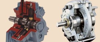
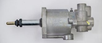
Piston pump for open-loop hydraulic systems
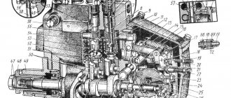
Design features
The main element of a liquid piston pump is a hollow metal cylinder, in which all work processes involving the pumped liquid take place. The physical effect on the liquid is carried out by a plunger-type piston. Thanks to this element, this liquid pump got its name.
The operating principle of a piston pump is based on the reciprocating movement of its working body, which acts as a hydraulic press. Moreover, in the design of such a machine, unlike classical hydraulic devices, there is a valve distribution mechanism, as well as a number of additional structural elements (in particular, a crank and connecting rod, which form the basis of the power part of a liquid piston-type pump).
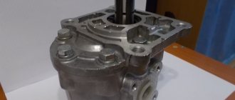
Axial piston pump design
Main varieties
According to its design, a piston hydraulic pump, like an axial-piston type hydraulic motor, can belong to one of the following categories:
- devices with a washer installed at a certain angle;
- axial piston pumps or hydraulic motors equipped with an inclined cylinder block.
The cylinder block of hydraulic motors and hydraulic pumps of the axial piston type, equipped with an inclined washer, is installed coaxially with respect to the drive shaft and is rigidly connected to it. The pistons moving in the grooves of the working chamber rest with their end surface on a washer, which is installed at an angle to the axis of the drive shaft. The principle of operation of such an axial piston pump is that when the drive shaft and swashplate connected to each other rotate together, the pistons of the device begin to move back and forth, thus reducing or increasing the volume of the working chambers.
When the volume of the working chambers begins to change, the liquid pumped through the pump is sucked in and pushed out. Devices with a swashplate are classified as adjustable hydraulic pumps, since by changing the angle at which the working surface of the swashplate is located, it is possible to change the flow parameters of the pumped liquid. Moreover, with the help of such a pumping device it is possible to reverse the water supply by changing the direction of the angle of inclination of the washer to the axis of the drive shaft to the opposite. Axial piston pumps equipped with a swashplate are installed in hydraulic systems operating under medium to high loads.
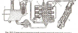
Schematic diagrams of axial piston hydraulic machines
The body of axial piston hydraulic pumps equipped with an inclined cylinder block has a V-shaped configuration, and their drive shaft is designed in the form of the letter T. The angle at which the cylinder block of the axial pump in question is located to the axis of the drive shaft can range from 26 to 40 °, and the number of pistons reaches 7 pieces. The operating principle of such an axial piston pump is as follows: when the drive shaft connected to the pistons through connecting rod mechanisms begins to rotate, the inclined cylinder block is also rotated, and the pistons located in the axial grooves begin to perform reciprocating movements, thereby reducing or increasing the volume of working chambers.
The process of suction and injection of the pumped working medium in axial piston pumps of this type is carried out through special openings-windows made in the distribution device, which is located motionless relative to the rotating inclined cylinder block. Unlike steam and radial piston pumps, in devices of this type the volume of the working chamber can be adjusted. This problem is solved by adjusting the angle of inclination of the cylinder block relative to the axis of the drive shaft using special mechanisms.
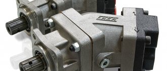
Axial piston pumps use a unified oscillating unit
Depending on how the design of an axial type plunger pump is implemented, it can be one of two types:
- In devices equipped with a double non-power cardan, full compliance of the angles measured between the intermediate, drive and driven shafts is achieved. When hydraulic pumps of this category operate, their shafts (drive and driven) move synchronously, which reduces the load on the cardan shaft, which, interacting with the disk, transmits torque.
- Axial piston type pumps have a design in which the pistons point contact with the surface of the inclined disk is implemented. This device does not have cardan and connecting rod mechanisms, which simplifies its design. The most significant disadvantage of axial piston pumps in this category is that to start them, it is necessary to force the piston elements out of the working chambers and then press their end part against the surface of the inclined disk. Meanwhile, due to the simplicity of the design, regular maintenance and repair of hydraulic pumps of this type is not very difficult.
Principle of operation
From most of those who select technical devices for equipping pipeline systems, specialists hear: “Explain the operation of a piston pump with an air chamber.” It should be said right away that the principle by which the liquid piston pump, invented several centuries ago, operates is quite simple. It consists of the following: by making a translational movement, the piston creates a vacuum of air in the working chamber, due to which liquid is sucked into the chamber from the supply pipeline. With the reverse movement of the piston of such a pump, which, according to some historical data, was invented by an ancient Greek mechanic, the liquid from the working chamber is pushed into the discharge line. Piston pumps, as mentioned above, are equipped with a valve mechanism, the main task of which is to prevent the pumped liquid from getting back into the suction channel at the moment when it is pushed into the discharge line.
Working principle of single-ended piston pump
The principle by which piston pumps operate explains the fact that the flow created by such devices moves through the pipeline at different speeds, in jumps. To avoid this negative phenomenon, they use pumps equipped with several pistons operating in a certain sequence. The advantages achieved when using liquid pumps with multiple pistons also lie in the fact that such devices are capable of pumping liquid even when their working chamber is not filled with it. This quality of a multi-piston plunger pump, which is called “dry suction,” is relevant in many areas where such devices are used.
Piston pumps vary in number of actions
Design features and principle of operation
If we consider the design of a centrifugal pump in cross-section, then the following elements can be distinguished in the design of such equipment.
- The electric motor in the centrifugal pump device plays the role of a driving element. That part of the internal structure of the centrifugal pump where its drive motor is located is carefully sealed, which is necessary to protect the power unit from contact with the pumped liquid medium.
- The pump shaft transmits rotation from the electric motor to the impeller.
- The design of a centrifugal pump necessarily includes an impeller, on the outer cylindrical surface of which there are blades that move the pumped liquid medium through the internal chamber of the device.
- Bearing units ensure easy rotation of the shaft with the impeller fixed on it.
- Sealing elements protect the components of the internal structure of the hydraulic machine from contact with the pumped liquid medium.
- The pump body, as a rule, is made in the shape of a snail and is equipped with two pipes - suction and pressure.
Main parts of a centrifugal pump
The design diagram of a centrifugal pump, in addition to the above parts, may include a number of additional elements:
- a hose through which the pumped liquid medium enters the pressure line;
- a hose through which liquid enters the internal chamber of the device;
- a check valve that prevents the movement of an already pumped liquid medium in the opposite direction;
- a coarse filter that prevents solid inclusions contained in the liquid medium from entering the inside of the pump;
- a vacuum gauge, with the help of which the degree of rarefaction of air in the working chamber is monitored;
- a pressure gauge, through which you can control the pressure of the liquid flow created by pumping equipment;
- elements of shut-off valves that allow you to regulate the parameters of the flow of liquid medium entering and exiting the pump.
Design of the pumping part of centrifugal type equipment
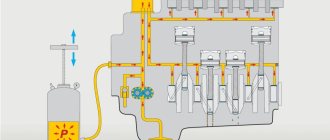
The design and principle of operation of any centrifugal pumps are simple. So, the principle of operation of a centrifugal pump is as follows.
- The liquid medium entering the internal working chamber is captured by the impeller blades and begins to move with them.
- Under the influence of centrifugal force, the liquid medium is thrown towards the walls of the working chamber, where excess pressure is created.
- Being under excess pressure, the liquid medium is pushed out through the pressure pipe.
- At the moment when the liquid medium from the central part of the working chamber is thrown towards the walls, an air vacuum is created, which ensures the suction of a new portion of liquid through the inlet pipe.
Operating principle of a centrifugal pump
The principle of operation of the centrifugal pump described above applies to both surface and submersible models. The main function of centrifugal pumping equipment is performed by an impeller with blades. In accordance with the principle of operation of centrifugal pumps described above, such devices ensure the suction of the pumped liquid medium and its expulsion into the pressure line in a constant mode, which guarantees the stability of the parameters of the created flow.
Double acting pumps
The main reason why the double-acting piston pump was developed and began to be actively used is the desire of manufacturers to reduce the level of pulsation in the flow of liquid pumped into the pipeline system. In order to understand the advantages of using a double-action pumping device, it is enough to understand how this type of piston liquid pump works.
A special feature of the double-action liquid piston pump design is that the rod and piston cavities of this machine are equipped with individual valve systems. This design of a double-action piston pump, the uniqueness of which can be seen even from the photo, allows not only to eliminate flow pulsations in the pipeline system, but also to significantly increase the efficiency of using the machine itself. Meanwhile, single-acting piston pumps, when compared with double-acting models, due to their simple design, are more reliable and durable.
Operating principle of a double-sided piston pump
There is another design scheme for a piston pump, which can be used to eliminate pulsation processes in pipeline systems. Pumping equipment made according to this scheme involves the use of a special hydraulic accumulator. The main purpose of such hydraulic accumulators used to equip pumping stations is to accumulate the energy of the fluid flow at moments of peak pressure in the pipeline and release it when such pressure is not enough for normal operation of the system.
However, no matter what types of piston pumps are used and no matter what additional technical devices the pumping stations are equipped with, it is not always possible to eliminate pulsation processes in pipelines. In such situations, additional equipment is often used to ensure effective removal of excess liquid outside the pumping station.
Fighting pulsation
One of the disadvantages of piston pumps, like other positive displacement pumps, is the pulsation of flow and pressure. Pulsations can be reduced by arranging several pistons in a row and connecting them to one shaft so that their operating cycles are shifted in phase relative to each other at equal angles. Another way to combat pulsation is to use a differential pump activation circuit (Fig. 2), in which liquid is pumped not only during the forward stroke of the piston, but also during the reverse stroke.
Double-acting pumps are also widely used, in which both the piston and rod chambers have (in contrast to the differential switching circuit) their own valve distribution system. Such pumps have a lower pulsation coefficient and higher efficiency than single-acting pumps (Fig. 1).
To combat pulsation, hydraulic accumulators are also used, which store energy at the moment of greatest pressure, and release it at the moment of pressure drop.
Areas of application
The scope of application of piston-type liquid pumps is quite wide, which is explained by their high versatility. Meanwhile, the design of such machines does not allow their use in cases where it is necessary to pump significant volumes of water or other liquid. One of the main advantages of these hydraulic machines is that their pistons, displacing liquid through the discharge line, simultaneously suck in a new portion of it through the supply channel, which is very important in dry cylinder conditions. This quality determines the purpose of piston liquid pumps as the most efficient devices used in chemical industry enterprises.
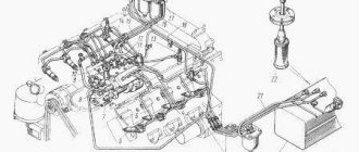
Hydraulic piston pump for truck crane
The scope of application of piston-type liquid pumps is also expanding due to the fact that such equipment can be successfully used to work with chemically aggressive media, certain types of fuel and explosive mixtures. Pumps of this type are also widely used for domestic purposes; with their help, it is possible to create pipeline systems for autonomous water supply to private buildings and for irrigation. Meanwhile, if you decide to use such a device, do not forget that it is not intended for pumping large volumes of liquid.
Another area in which piston-type liquid pumps are actively used is the food industry. This is explained by the fact that such devices are distinguished by a very delicate attitude towards the liquid pumped through them.
Piston pumps, High pressure pumps
General description:
High pressure water jet cutting systems are characterized by high quality and dynamics. All design elements used are selected based on years of experience in waterjet cutting technology and are optimized for use in harsh environmental conditions.
The tool is controlled in a Cartesian coordinate system.
All necessary coordinate transformations are calculated online using CNC.
All high-pressure water jet cutting systems we supply comply with safety regulations in accordance with European Union standards.
The recovery tank, designed specifically for the needs of water jet cutting, absorbs the residual energy of the abrasive jet that remains after cutting the workpiece and converts it into heat.
Installation design:
The installation frame is made of welded, heat-treated steel and is designed in the form of a “mobile bridge (portal)” with a fixed table. The mobile bridge moves longitudinally (Y-axis), while the X-axis crosses the Y-axis (transverse movement). The Z axis for vertical movements, controlled by CNC, is mounted on the X axis (bridge). The longitudinal axes (y1 and y2) are designed as a connection/coupling of the frames. CNC guarantees high-precision synchronized movement of the longitudinal axes. This setting provides higher accelerations and straightness control along the entire length of the bridge. The design of the installation provides ease of access. The movements of the machine axes are complemented by appropriate guards and protected by waterproof bellows, which prevent the penetration of water, fine dust and, if necessary, foreign bodies between the moving elements. The automatic lubrication unit, controlled by CNC, guarantees a very long service life and precision of the drive and guide elements.
Installation Specification
Travel range: X-axis: 3,000mm Y-axis: 9,000mm Z-axis: 200mm Feed speed: 0 - 30m/min Max. working area: 3000mm x 9000mm
Cutting table
The bathtub is made of steel and equipped with gaskets made of sheet material. The gaskets are removed individually so that only parts worn by the jet can be replaced. A workpiece table that is stationary during processing offers significant advantages: easy loading and unloading of workpieces (since the work area is completely free and stationary), simple use of clamping systems and accessories. The water contained in the bath minimizes the noise produced by the water jet and ensures an acceptable noise level (from 75 to 80 dBA). The water level in the bath is regulated using a drain located on the outside.
Abrasive water jet cutting head
The cutting head consists of a nozzle and a cutting pipe, which focuses water and abrasive. The cutting head is mounted on the Z axis. Due to the special design concept of this head, there is no need to center the water jet using focusing nozzles. The cutting head is designed in such a way that it can be replaced without the use of special tools. This serves to optimally minimize downtime. Further, the use of focusing durable nozzles ensures a longer service life. The pneumatic changeover valve is an N/C (normally closed) type valve. The cutting head consists of only three wearing parts: water nozzle, mixing chamber and cutting pipe. These parts are made from highly wear-resistant materials to ensure the highest production efficiency. For safety reasons, the cutting head is usually closed. The opening and closing of the head is controlled by CNC.
Safety device
The installation is standard and protected from interference during operation. This solution ensures that the installation complies with safety regulations.
Abrasive supply and dosage device
The installation consists of a main tank and a system for supplying abrasive to the jet using an electronically controlled dispenser for precise adjustment of productivity. The sensor monitors the filling level and gives a signal when the abrasive runs out. The abrasive is supplied by compressed air to the abrasive dispenser mounted on the X-axis. The amount of abrasive entering the cutting head is programmable.
High-pressure pump Capacity: 37 kW Voltage: 400V/3/50Hz Max. operating pressure: 4,130bar Minimum pressure: 520bar
Computer-aided design and programming software
CNC installation
The CNC installation contains the following components:
- Control Panel
- CPU
- Control card with axes
Control and programming of water jet cutting installation
Main functions of CNC:
- Simultaneous control of up to 4 axes with linear, circular and helical interpolation.
- Simultaneous programming during processing.
- Rechecking the programmed profile and tool using a graphical display on the monitor.
- Alignment of the radius and length of the workpiece.
- Cyclic shift of the cutting program
- Automatic speed matching via acceleration and/or deceleration ramps.
- Reflection function
- Performing a program while passing a tool without cutting - to simulate the execution of a cutting program in order to double-check the correctness of execution.
- Communication via serial interface for data transfer between PC and CNC
- USB interface for entering and reading cutting program data
- Ethernet communication provides a connection between the plant CNC and the local network or production
Advantages and disadvantages
If we talk about the advantages of piston-type pumps used for pumping liquid media, the most significant include:
- simplicity of design, which is demonstrated even by pictures and schematic representations of such devices;
- high reliability, which is determined not only by the use of high-strength materials for the production of such machines, but also by the operating principle of the piston pump;
- the ability to work with media, the use of which imposes special requirements on the start-up conditions of pumping equipment.
The main disadvantage of the pumping equipment in question, mentioned above, is its low productivity. Of course, it is possible to expand the technical capabilities of such devices, but why do this if this task is solved at lower financial costs using another type of pumping equipment.
When choosing piston-type liquid pumps, first decide what the equipment will be used for. If you do not intend to pump too large volumes of liquid, then affordable and reliable piston-type liquid pumps are optimal for achieving your goals.
Types of piston installations
Piston pumping devices have different modifications. Thus, the devices come in vertical or horizontal versions, with manual and mechanical drive.
Based on the type of working element that displaces liquid, the following units are distinguished:
1. Piston, where the piston is in the form of a disk.
2. Plunger. The piston is presented in the form of a hollow long cylinder.
3. Diaphragm. The pumped product is separated from the piston by a diaphragm, and an emulsion or oil is poured into the cylindrical chamber. The devices are used for pumping aggressive substances, mortars, and products with impurities.
According to their mode of action, the devices are produced:
1. Single action.
2. Double. They have 2 working chambers, each equipped with a discharge and suction valve, which significantly reduces flow pulsation.
3. Differential piston devices. They also have 2 chambers, but one of them lacks valves. The fluid flow becomes even more uniform.
By piston size:
- with a large piston diameter (over 150 mm);
- with medium (50–150 mm);
- with small (up to 50 mm).
According to the degree of speed of the working element, they are distinguished:
- low-speed devices (make 40–80 double moves every minute);
- medium speed (50–80 moves);
- high-speed (150–350 moves).
Jet pump types
Designed to work with all types of liquids. Jet pumps can be installed vertically or horizontally. The units are designed with multiple inlets that are used to suck in a constant flow of fluid using pressure to create lift. Suction pressure and fluid velocity force the fluid from the source, transporting it to the end point.
A jet pump or injector combines the functions of a jet and a centrifugal device. Structurally, the presence of a part of a centrifugal pump as part of a jet pump is specially designed to work in combination with an injector. The injector itself increases the pressure of the centrifugal pump by approximately 60 percent, providing the required pressure. Jet pumps are superior to centrifugal pumps precisely because of their ability to increase pressure.
Depending on the depth of the well, the operating principle of the equipment is determined. Thus, for use in a shallow bottom well, a pipe is connected to the well inlet and passes down into a source of liquid. If you need to pump water from a deeper source, you need two water channels. One is used to displace water, the second is used for rinsing water. Jet pumps for deep wells are single-pipe and double-pipe.
For the operation of all jet pumps, a universal rule applies: there must be a check valve at the bottom of the suction pipe. This system prevents water from getting back into the well when the equipment is turned off. Many jet pumps are self-priming, so they can maintain a sufficient vacuum level to suck up liquid.
When choosing a jet pump, the type of liquid being pumped must be taken into account. The flow speed depends on it. For example, in wells containing solid particles, it is better to use a unit with an annular nozzle. Jet pumps can be made of high-strength types of plastic, steel, and stainless steel. If you choose materials that are susceptible to corrosion, it is imperative to provide anti-corrosion protection.
Plunger pump: operating principle, types and applications
Old pumping equipment designed for pumping water is gradually being eliminated from home and industrial environments. Now, instead of the traditional piston device, a plunger pump is used, aimed at mixing the various components of the liquid and dispensing them correctly. Often, even in everyday conditions, there is a need to create a solution from several liquid components. In such cases, the mechanism will be an excellent assistant.
Design features and principle of operation
Branded plunger pump
According to its characteristics, the device belongs to the class of hydraulic mechanisms. All these designs are divided into volumetric and non-volumetric and are a type of piston units. The only difference between the pumps is the cylindrical piston installed inside for operation, called a plunger. During operation, the metal rod has no contact with the walls of the pump housing. These dosing type instruments have plungers that meet the qualities of strength, durability and sealing.
The performance of the installation is based on the movement of a cylindrical piston (plunger). If this mechanism progressively moves to the right, the pressure in the mechanism decreases, while its performance in the suction pipe remains at the proper level. If the plunger is directed in the opposite direction, the reverse process occurs.
Important! If there is a change in the pressure levels of the plunger mechanism, pulsating movements may occur, which is unsafe for the further performance of the structure. These cases are characterized by eliminating the problem
Types of plunger pumps and their characteristics
Each water pumping equipment is divided into types, thanks to which the use of the units becomes more convenient and the operation features are practical. It has been proven that water plunger pumps act like a piston unit, so their varieties can be similar. Based on design features, water pumps are divided into:
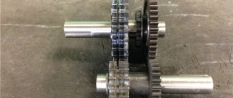
Plunger pump design drawing
- horizontal;
- vertical;
- multi-ploughed or single-ploughed;
- by type of control: automatic or manual;
- with or without heating;
- multi-cylinder and single-cylinder;
- with sealant on the cylinders.
Now let's look at the design principle of the listed varieties in order.
In horizontal plunger installations, the operating mechanism is a starting valve, which does not require special processing of the cylinder, as happens in a traditional piston-type pump. The design is sealed with an oil seal, thereby increasing the functionality of the cylinder.
In the vertical type of liquid pump, the working mechanism is an empty glass. The design is subject to long-term operation due to the installed seal. If the mechanism becomes loose, it can be easily tightened and, if necessary, the oil seal can be replaced. Its application is concentrated in blue-collar industries.
The presence of a heating jacket is necessary for the cooling effect of the system. This allows such a pump to operate continuously; in the absence of such a function, it is recommended to create an individual operating mode for the liquid unit.
Industrial plunger pump
Multi-plunger pumps differ from single-plunger pumps in the number of rotational mechanisms; if a single pump has only one rod, then the second has more than three.
The plunger liquid pump can be equipped with automatic or manual configuration. The principle of control of the installation depends on this. The device is also distinguished by the number of cylinders and the presence of a sealed layer on them.
Attention! The dosing pump must meet all the characteristics specified in relation to it in the passport. Otherwise, the installation is considered inoperative. If you find any problems with the pump, be sure to stop using it.
If you find any problems with the pump, be sure to stop using it.