The general purpose roller header is used for mowing and stacking grain and cereal crops. The industry produces specialized headers - for harvesting a certain type of plant (sunflower, corn, legumes), for example, a corn header. The most widespread are self-propelled, trailed and mounted (side, front) units. Depending on the number of formed rolls, the width of which can be adjusted, it is possible to use one-, two- and three-flow headers. By adjusting, you can select the optimal cutting height of plant stems, rotation speed and reel position, and balance the balancing mechanism to accurately follow the field profile. Modern headers have a processing width of 6 to 10 meters. Operating speed can reach 12 km/h.
Harvester ZhVN-6
The abbreviation ZhVN stands for mounted roller header, and the number 6 is the working width. It is used on domestic combine harvesters “Niva”, “Sibiryak”, “Yenisei”. Since it is not always advisable to use a grain harvester only for mowing crops to form a windrow, it is possible to install ZhVN-6 on mower-conditioners of the KPS-5G, E-302, E-303 types.
The header ZhVN-6 is produced by PJSC "Berdyansk Reapers" - a manufacturing plant specializing in the production of equipment aimed at harvesting grain and leguminous crops.
After turning the combine, the next windrow is placed next to the previously formed one, which ensures a simpler procedure for subsequent threshing. At the same time, the outlet window has an adjustable hole, which ensures the use of the header on crops with different yields.
See also:
Trailed roller header ZhVP-4.9
Price: 429,400
rub.
More details
Trailed roller header ZhVN-6.4 “Berdyansk reapers”
Price: 863,253
rub.
More details
Trailed roller header ZhVP-6.4 Schumacher “Berdyansk Reapers”
Price: 1,026,608
rub.
More details
Trailed roller header ZhVP-6.4 with MPN
Price: 863,253
rub.
More details
Trailed roller header ZhVP-4.9 “Berdyansk reapers”
Price: On request
Read more
Trailed roller header ZhVP-4.9 Schumacher “Berdyansk Reapers”
Price: On request
Read more
Trailed roller header ZhVP-4.9 with MPN “Berdyansk reapers”
Price: On request
Read more
Trailed roller header ZhVP-9.1 with MPN “Berdyansk reapers”
Price:
RUB
1,028,948 More details
Trailed roller header ZhVP-9.1 Schumacher “Berdyansk Reapers”
Price:
RUB
1,199,540 More details
Device
The design of the ZhVN-6 header is, in principle, standard. There is a body with a tow hitch. On the sides of the header under the protective shields there is a drive mechanism. The crop is mowed using a finger segmental scythe. The scythe is driven by an angular gearbox.
The angular gearbox is planetary, made according to the Schumacher type. Therefore, this header is often called “Schumacher”.
In the upper part there is a 5-blade reel with rakes, which tilts the stem in the desired direction before cutting. Behind the scythe there are three narrow belts, with installed wooden slats, which ensure that the beveled stems are captured and fed into the exit window. Schumacher header diagram
1 — cutting device, 2 — reel; 3 — side panels; 4 — hydraulic cylinder rods; 5 — connecting rod; 6 — variator; 7 — support; 10 — wind shield; 11 — shield; 12 - reel; 13 - rakes; 14 — dividing capes; 15 - window.
Purpose, structure of the windrower (page 1 of 4)
Test question number
Correct answer number
Question 1: Describe the purpose and structure of the windrower and diagram it.
Windrow harvesters are designed for cutting stems during separate harvesting and placing them in windrows for ripening and drying. Windrow harvesters can be trailed or mounted on a combine, tractor or self-propelled chassis. According to the location of the cutting apparatus, they are divided into frontal and lateral. According to their purpose, reapers can be general-purpose or special for harvesting certain crops.
According to the method of forming the windrow, the headers are distinguished as single-, double- and triple-flow. Single-flow machines place windrows outside the design working width. Double-flow machines form a windrow in the ejection window located at the end of the header platform. In this case, one stream of mown mass is formed by the header conveyor, and the second is placed directly through the header ejection window behind the cutterbar. Three-flow headers form a swath in the central window, on both sides of which there are conveyors that create two counter flows, the third flow is formed in the ejection window.
For mowing grain into windrows, windrowers ZHRS-5, ZhVN-6A, ZhVR-10, ZHRB-4.2A, ZHRK-5, ZHRS-5 are used. Mounted front-mounted headers mow and mow fields in preparation for separate harvesting.
Rice. 1. Scheme of the working process of windrowers: a - ZhVN-6A; b — ZhRS-5; c and d — ZhVR-10; d—wide-section modular; 1 - reel; 2 - rake; 3 — cutting apparatus; 4, 8, 9, 12. 19 — conveyors; 5 — shoes; 6 - roll; 7 - window; 10 and 20 - energy agent; 11 - grain harvester.
The ZhVN-6A mounted header (Fig. 2) includes a cutting device 1, a reel 12, a belt-slat conveyor 2, and a drive mechanism mounted on a platform. The platform is a welded frame covered with steel sheet. Wind shield 10 prevents the mown mass from falling from the conveyor. On the sides of the hull there are side shields 3, which turn into cape dividers 14. When harvesting long-straw grains, the capes 14 are removed and torpedo dividers are installed, intended for supplying stems located to the left and right of the edge of the apparatus to the cutting apparatus.
The cutting apparatus consists of a finger bar, a segment knife and a crank drive mechanism. Reel 12 consists of a shaft with crosses, to the arms of which are attached rakes 13. Spring fingers are attached to the rakes, which comb the tangled and laid grains well and bring them to the cutting apparatus. When harvesting upright grain, slats are attached to the tines of the rake. The reel shaft bearings are mounted on sliders that can be moved along supports 7, resting on the rods of hydraulic cylinders 4. The reel shaft, equipped with a safety clutch, rotates from the variator 6, with the help of which the reel rotation speed is changed from 22 to 58 min -1.
Rice. 2. Windrow harvester ZhVN-6A: 1 — cutting device; 2 - conveyor; 3 — side shield; 4 - hydraulic cylinder; 5 connecting rod; c — variator; 7 — reel support; 8 — spring block; 9 — inclined chamber of the combine; 10 — wind shield; 11 — guide plate; 12 - reel; 13 rake; 14 — cape-divider; 15 - window. The combine operator raises and lowers the reel and adjusts its rotation speed while the machine is moving. Conveyor 2 is made up of six belt-slat belts that move in streams stamped into the header flooring. The tapes are tensioned on the drive and driven (tension) rollers. The length of the conveyor 2 is less than the length of the cutting device. Therefore, window 15 is located to the left of the conveyor.
Trailed header,
includes cutting apparatus 1, reel 12, belt-slat conveyor 2, drive mechanism, mounted on the platform. The platform is a welded frame covered with steel sheet.
Self-propelled reaper ZH.RS-5 (Fig. 1, b), designed for mowing rice, consists of a counter-flow reaper and energy means 10. The cutting apparatus, reel and conveyors 8 and 9 are mounted on the reaper platform. The cutting apparatus cuts the plants, and the reel places them on conveyor belts 8 and 9, moving towards one another. Conveyors throw the stems into window 7, located in the center of the platform. Therefore, a windrow formed from two counter flows of grain mass is characterized by good connectivity of stems and a fan-shaped arrangement of ears. The working width of the header is 5 m. For harvesting rice, the ZHRK-5 header is also used, mounted on the Yenisei-1200R combine harvester. The ZhVR-10 doubling header (Fig. 1, c and d) is equipped with two belt-slat conveyors 8 and 9, mounted on movable frames. The latter can be moved relative to the header body to the left and right, adjusting the position of the ejection window. When the conveyors are displaced, the reversible gearbox changes the direction of their movement relative to the resulting ejection window. When mowing high-yielding grains, the conveyors are moved apart, and a window 7 is formed between them (Fig. 1, c), into which the cut stems are thrown. When mowing low-growing and sparse grains, the frame of the small conveyor 9 is fastened to the frame of the main conveyor 8 and they are simultaneously shifted to the left or right (Fig. 1, d). In this case, the unloading window is located alternately on the left or right, and in two passes it is possible to form a double windrow from a strip of 20 m. For better transverse copying, the header body is made of two sections, hingedly connected to each other. The sections are equipped with a lever-spring balancing mechanism, which, together with the support shoes of the main and support wheels of the additional sections, ensures that the header follows the field topography in the longitudinal and transverse directions. The cutting height is adjusted by moving the support shoes and wheels vertically. The rotation speed of the reel is changed by a hydraulic variator, and the height position of the reel is changed by hydraulic cylinders. Shift the reel forward and backward along the supports and change the inclination of the rake fingers manually when the gear is off. The ZhVR-10 header is mounted on all grain harvesters and the energy means of the KPS-5G mower. The working width of the header is 10 m. To transport the header on roads, a special trolley and tow hitch are used, which are mounted on the combine.
The wide-cut modular header (Fig. 1, e) is designed for mowing grain crops in areas with relatively low yields. The reaper consists of a front and two side reaping modules mounted on a universal energy device 20. Four mobile conveyors 14, 15, 16 and 17 are mounted on the platform of the front module 1. The main 12 and 19 and removable conveyors 13 and 18 are installed on the platforms of the side modules. In this configuration, the header can form a windrow from a strip whose width is equal to the sum of the working grips of three modules. If necessary, such a header can form two windrows. To do this, conveyors 15 and 16 are shifted to the center and the direction of their movement is reversed, and conveyors 13 and 18 of the side modules are dismantled. In this case, the windrows will be laid on both sides of the running wheels of the energy vehicle along lines A and B. The self-propelled harvesting complex USK-17A “Steppe” operates according to this scheme, the total working width of the reaping modules is 17 m.
Modifications
Features of the operation of the ZhVN-6 header include periodic checking and lubrication of drive mechanisms, checking the condition of fasteners and the condition of the scythe segments.
In general, ZhVN-6 is a general designation for headers, since there are several modifications of them that differ in certain design features. So, the basic one is the ZhVN-6B header. It uses a certain type of drive, and the scythe is driven by a crank gearbox.
There are other headers, for example, ZhVN-6A, but the main differences between them come down to the type of drive and gearbox. Also, some of them have wider applicability on equipment. But the main characteristics of these headers are the same.
Windrow harvester ZhVN-6: characteristics and design
SECTION 14 ROLLER HEADERS
Mounted windrower ZhVN-6
The header is designed for mowing and windrowing grain mass of grain crops using a separate (two-phase) harvesting method.
Technical characteristics of windrower headers are given in Table 9.
The header is mounted on self-propelled combines SK-4, SKD-5 "Sibiryak", SK-5 "Niva". The header is balanced and copies the field topography in the longitudinal and transverse directions at a given cutting height.
When harvesting dead grain, 26 stem lifters are installed on it, the same as on a conventional auger harvester. After installing the crop lifters on the header, the reel rakes are bent at the points where the rakes touch the stem lifter feather.
The header consists of the following main assembly units and mechanisms: an inclined body, a platform, a cutting apparatus, a reel, a belt-slat conveyor, drive mechanisms for working parts, a hydraulic system, follower shoes, supports, a header, and drive guards.
When attaching the header to a combine, the inclined body is hinged in two cages located on the front struts of the thresher, and rests it on two hydraulic cylinders for lifting the header, installed on the axle housing of the drive wheels of the combine.
A belt-slat conveyor, a reel, and a cutting apparatus are mounted on the header platform. The ejection window is located on the left side.
Lightweight mowing cutter of normal cutting type, with anti-rust plates and clamps.
The header reel is eccentric or slatted with a safety clutch. The reel rotation speed is varied by a V-belt variator, controlled hydraulically from the combine operator’s workplace.
The belt-slat conveyor consists of rubberized belts 125 mm wide with wooden slats riveted onto them. Depending on the height of the grain stand and the yield, four or five conveyor belts are installed on the header.
The drive mechanism of the working parts of the header includes a telescopic cardan shaft, transmission shaft and gearbox. Copying shoes are designed to copy the field topography at the established cutting height.
The header is prepared for work in the following sequence: the header supports are placed in the working position; the reel beam is installed on wooden bearings on the brackets of the upper belt of the wind shield, having previously placed dimensional reflectors under the outer bearings; insert the rods of the reel lifting hydraulic cylinders between the reel support sectors and fix them with fingers on the central holes of the support sectors.
If the rakes or reel bars touch the cutting apparatus, then the hydraulic cylinder rods are secured to the outermost holes of the sectors.
A drive V-belt is put on the reel variator pulleys. If the pulleys are not in the same plane, then special adjusting washers are placed between the lower pulley bracket and the header side plate.
Connection of the inclined body to the header platform. The inclined body is connected to the header platform like this. Install pins 3 (Fig. 118) with rollers 4 on it, remove the spherical ring, bolt and castle nut from the central bracket, move the layers and balancing springs on both sides of the inclined body from the position set when shipping the header to the working one, for which they unpin and remove lever 2 from pipe 1, set it in the position shown in the figure, and secure it with a cotter pin. Bring the inclined body to the header so that the cage of the Central hinge with the spherical ring fits into the bracket on the rear beam of the header, and connect them with a bolt, tightening the nut until it stops, which is then secured with a cotter pin. Before assembly, the holder and spherical ring of the hinge are generously lubricated with universal grease. The hinged suspension 5 blocks of balancing springs are inserted into the ears 6 on the main beam 8, connected with fingers 7, which are secured with cotter pins.
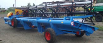
Trailed roller header ZhVP - 6.4
The trailed roller header ZhVP-6.4 is used for mowing grain and cereal crops with placing the mown mass in a single counter-flow windrow in all zones where a separate harvesting method is used.
Photo of windrower ZhVP-6.4
The ZhVP header provides:
- laying windrows of good quality and optimal power;
- high productivity of mowing and picking;
- facilitating the working conditions of the machine operator.
The use of the trailed header ZhVP - 6.4 allows you to:
- reduce costs for separate cleaning;
- free some combines from working with windrower headers;
- load the transport fleet more optimally.
Features of the windrower
- belt-slat conveyors;
- MKSh swing washer mechanism;
- has a device for quick and convenient transition to the working and transport position;
- an improved aggregation system ensures smooth running and accurate copying of the field topography;
Other machines, such as a grain thrower, are also successfully used on the farm.
Technical characteristics of ZhVP headers
| Model | ZhVP-4.9(A) | ZhVP-6.4(A) | ZhVP-9.1A |
| Working width, m | 4,9 | 6,4 | 9,1 |
| Operating speed, no more, km/h | 10 | 9 | 9 |
| Productivity, ha/h, up to | 4,9 | 5,76 | 8,19 |
| Cutting height, mm | 80-250 | 80-250 | 80-250 |
| type of drive | KShP (MPN) | MKS (MPN) | MPN |
| Header weight, kg | 1545 (1564) | 2000 | 2200 |
| Aggregation, because | 1,4 | 1,4-2,0 | 1,4-2,0 |
KShP – crank drive; MKSh – swing washer mechanism; MPN is a Schumacher-type planetary mechanism with a vertical pulley arrangement.
Video review of the testing of the ZhVP-6.4 header
Windrow harvester ZhVN-6: characteristics and design
Question 1: Describe the purpose and structure of the windrower and diagram it.
Windrow harvesters are designed for cutting stems during separate harvesting and placing them in windrows for ripening and drying. Windrow harvesters can be trailed or mounted on a combine, tractor or self-propelled chassis. According to the location of the cutting apparatus, they are divided into frontal and lateral. According to their purpose, reapers can be general-purpose or special for harvesting certain crops.
According to the method of forming the windrow, the headers are distinguished as single-, double- and triple-flow. Single-flow machines place windrows outside the design working width. Double-flow machines form a windrow in the ejection window located at the end of the header platform. In this case, one stream of mown mass is formed by the header conveyor, and the second is placed directly through the header ejection window behind the cutterbar. Three-flow headers form a swath in the central window, on both sides of which there are conveyors that create two counter flows, the third flow is formed in the ejection window. For mowing grain into windrows, windrowers ZHRS-5, ZhVN-6A, ZhVR-10, ZHRB-4.2A, ZHRK-5, ZHRS-5 are used. Mounted front-mounted headers mow and mow fields in preparation for separate harvesting. Rice. 1. Scheme of the working process of windrower headers:
a — ZhVN-6A; b — ZhRS-5; c and d — ZhVR-10; d—wide-section modular; 1 - reel; 2 - rake; 3 — cutting apparatus; 4, 8, 9, 12…19 — conveyors; 5 — shoes; 6 - roll; 7 - window; 10 and 20 - energy agent; 11 - grain harvester.
The ZhVN-6A mounted header (Fig. 2) includes a cutting device 1, a reel 12, a belt-slat conveyor 2, and a drive mechanism mounted on a platform. The platform is a welded frame covered with steel sheet.
Wind shield 10 prevents the mown mass from falling from the conveyor. On the sides of the hull there are side shields 3, which turn into cape-dividers 14.
When harvesting long-straw grains, the capes 14 are removed and torpedo dividers are installed, designed to supply stems located to the left and right of the edge of the apparatus to the cutting apparatus.
Reel 12 consists of a shaft with crosses, to the arms of which are attached rakes 13. Spring fingers are attached to the rakes, which comb the tangled and laid grains well and bring them to the cutting apparatus. When harvesting upright grain, slats are attached to the tines of the rake.
The reel shaft bearings are mounted on sliders, which can be moved along supports 7, resting on the rods of hydraulic cylinders 4. The reel shaft, equipped with a safety clutch, rotates from the variator 6, with the help of which the reel rotation speed is changed from 22 to 58 rpm.
Rice. 2. Windrow harvester ZhVN-6A: 1 — cutting device; 2 - conveyor; 3 — side shield; 4 - hydraulic cylinder; 5 connecting rod; c — variator; 7 — reel support; 8 — spring block; 9 — inclined chamber of the combine; 10 — wind shield; 11 — guide plate; 12 - reel; 13 rake; 14 — cape-divider; 15 - window. The combine operator raises and lowers the reel and adjusts its rotation speed while the machine is moving. Conveyor 2 is made up of six belt-slat belts that move in streams stamped into the header flooring. The tapes are tensioned on the drive and driven (tension) rollers. The length of the conveyor 2 is less than the length of the cutting device. Therefore, window 15 is located to the left of the conveyor.
The header is hung on the inclined chamber of the SK-5A Niva combine harvester, which in this case performs the function of an energy source. During operation, the header body rests on two shoes 5 (Fig. 1, a), installed under the bottom of the header. The shoes slide along the stubble, follow the field topography and support the cutting device at a given height. The rakes 2 of the reel 1 capture a portion of the stems, bring them to the cutting device 3 and, after cutting, place the stems on the conveyor 4. The latter moves the stems to the left to the window 7 and throws them onto the stubble in the form of a continuous windrow 6. The width of the windrow is adjusted by rearranging the shield 11 (see. Fig. 2), and the cutting height - by rearranging the copying shoes. The tension of the spring block of the combine feeder chamber is adjusted so that the pressure of the shoes on the soil does not exceed 250...300 N.
Disassembly, assembly and adjustment of the working parts of the ZhVN-6A header
Disassemble, assemble and adjust the belt-slat conveyor:
- Remove the reel and place it on stands.
- Turning the pulley 10 of the upper shaft of the hinge body 8, install the fifth conveyor belt with its ends connected from above at the ejection window 45 (see Fig. 22).
- Pull the end of the belt 3 (Fig. 23), release the clamp 2 and remove the clamp 1.
- Pull out the conveyor belt. Remove the remaining tapes in the same way.
- Install the tapes in the reverse order: turn the end of the tape with one pair of holes with the slats down and insert it from the side of the ejection window between the upper and lower decking and push it until the end goes beyond the lower decking.
- Pass each tape from below between the drive roller of the Conveyor and the right side of the header and pull it manually along the stream of the upper deck towards the ejection window, not reaching it 300-400 mm. Pull the tapes with tension belts 3 and tighten with clamps 2.
- Check the tension of the tape by pulling it from the middle with a dynamometer with a force of 10 kgf (98.07 N). The lifting height of the tape should be 200-250 mm. Measure the lifting height of the tape with a ruler. If necessary, tighten or loosen the conveyor belt with belt 3 (Fig. 23), threaded through gripper 1, and clamp it with a clamp.
Disassemble the lower shaft of the inclined housing of the ZhVN-6A header:
- Loosen the locknut and unscrew the locking bolt 4 (Fig. 24). Remove pulley 2 from shaft 1.
- Remove the housing cover 13 of the right bearing by unscrewing the nuts and removing bolts 7. Press o-ring 14 out of the cover. Unscrew the nut from the bearing sleeve.
- Loosen the locknut and unscrew bolt 9. Remove crosspiece 11 from shaft 1.
- Unscrew the nut and locknut. Remove the bolts and bearing housing 13 from the sidewall of the header inclined housing.
- Press ball bearing 8 and sealing ring 14 out of housing 13.
- Repeat steps 4 and 5 and disassemble the right bearing.
- Remove the shaft from the inclined housing and knock out the key.
Assemble the lower shaft of the header inclined housing:
- Press sealing rings into bearing caps 8 and into their housings. Check the installation of the springs inside the rings. Press the bearings into the housings until they touch the shoulder.
- Insert the shaft into the inclined housing and slide the bearing housings 6 and 13 assemblies onto the shaft. Align the holes in the right bearing housing with the holes in the inclined housing. Place three bolts in the holes and secure them with nuts and locknuts.
- Secure the bearing to the shaft by tightening the split sleeve nut. Secure the nut with a washer. Place the cover on the bearing housing.
- Assemble and install the left bearing by repeating steps 2 and 3.
- Fit key 3 along the groove of the shaft and pulley. Place the pulley on the shaft and secure it to the key by screwing in the locking bolt and locknut.
Disassemble the gearbox with the drive shaft of the ZhVN-6A header conveyor:
- Unscrew the bolts securing the upper gearbox cover and remove it.
- Remove the ball bearing cover 3 and press out the sealing ring 2. Unscrew the nut 1, bending the washer's antennae (Fig. 25).
- Press ball bearing 4 off the shaft. Remove shaft 14 and gear 9 from gearbox housing 6. Unscrew bolt 16 and remove its lock washer.
- Remove gear 8 and shims 17 from the shaft and knock out keys 10 and 15 from the shafts.
- Unscrew the two bolts of cover 21 and remove the drive shaft 19 of the conveyor from the gearbox housing 6.
- Press ball bearing 18 off shaft 19 and then remove cover 21 from the shaft.
Assemble the gearbox:
- Press the O-rings into the gearbox covers. Press ball bearing 11 onto shaft 14 until it stops.
- Place cover 21 on the pin of the drive shaft of the conveyor 19.
- Insert gear 8 into the gearbox housing. Place a package of adjusting shims 17 about 2 mm thick on the shaft journal 19. Insert key 15 into the keyway of the shaft and place bevel gear 8 on the shaft. Push shaft 19 until the ball bearing 18 stops in the gearbox housing. Screw bolt 16 into the end of drive shaft 19, installing a lock washer under the bolt.
- Insert shaft 14 into the gearbox housing. Place the key in the groove on the shaft and put on bevel gear 9. Press bearing 11 onto the shaft and place it in the hole in the gearbox housing.
- Install gasket 12 on the cover, put the cover on the shaft, secure with bolts, placing washers under them.
- Place spacer pipe 7 on the gearbox shaft and slide it along the shaft until it stops against gear 9. Insert the dummy ball bearing 4 into the hole in the gearbox housing and move pipe 7 all the way into the dummy.
- Measure the gap between the ends of gear 9 and pipe 7 with a feeler gauge to determine the thickness of the adjusting shims 5. Knock out the dummy ball bearing 4 from the housing hole.
- Place the gaskets 5 onto the gearbox shaft until it stops at the end of the tube 7. Press the ball bearing 4 onto the gearbox shaft and place it in the housing hole until it stops.
- Place the washer on the shaft 14, screw on the nut 1. Lock the nut by unscrewing the washer tab into the groove of the nut. Place cover 3 with a gasket on the shaft and secure it to the body with two bolts.
- Check the size of the lateral clearance between the gear teeth by rolling a lead plate 0.5-0.4 mm thick between them. The permissible side clearance for new gears is 0.1-0.16 mm, for a run-in pair - 0.2 mm. The gap is adjusted by installing gaskets 5 and 17.
- Install a dial indicator and measure the axial movements of the shafts. They should be no more than 0.05-0.1 mm. If they move more, replace the bearings.
- Install the gasket on the gear housing. Place the top cover and secure it with five bolts.
Perform adjustments to the working parts of mounted windrow headers:
- Set the header cutting apparatus to the minimum cutting height: align one of the holes in the shoe lever with the hole in the gusset of the header main beam with the platform hanging on stands.
- Determine the set cutting height by measuring with a ruler the distance from the middle of the knife segment to the surface of the floor or platform, and from the reference plane of the shoe to the same surface. Subtract the second from the first value to determine the cutting height.
By rearranging the tracking shoes, the installation cutting height of the ZhVN-6A, ZhShN-6 and ZhNS-6-12 headers is adjusted. Typically, the minimum cutting height varies between 50-100 mm.
By rearranging the support wheels of the ZhBA-3.5A header, you can obtain a cutting height of 60 mm.
The cutting height is adjusted by the support wheels of the ZhShN-6 and ZhBA-3.5A headers when working on wet soil, when the shoes stick. When working in fields littered with stones, the cutting height can be set by hydraulic cylinders for lifting the headers.
Adjust the tension of the springs of the header balancing mechanism with the movable conveyor frame (ZhNS-6-12):
- Place the movable frame in the middle position.
- Tension the left and right spring blocks so that the effort to lift the finger beam with a dynamometer by the right and left ends is 25-30 kgf (245.19-294.2 N) for hard dry soils and 15-20 kgf (147.09-196 .13 N) for loose wet fields.
- Move the conveyor frame to the right extreme position and adjust the tension of the left spring of the balancing mechanism.
- Move the frame to the left extreme position and adjust the pressure on the left shoe by tensioning the right spring of the balancing mechanism.
- Move the frame to the extreme right position, check the efforts to lift the pin beam and, if necessary, repeat the indicated adjustments.
The pressure of the support wheels and shoes of the ZhBA-3.5A and ZhVN-6A headers is regulated by changing the tension of the springs of the balancing mechanism. The procedure for making this adjustment is described in. work 2.
Adjust the cutting apparatus of the headers:
- Install a pick-up shield on the finger beam of the ZhVN-6A and ZhNS-6-12 headers to reduce the working width from 6 to 5 m, as when harvesting high-yield crops.
- Check the coincidence of the center lines of the segments with the center lines of the fingers by moving the knife through the drive mechanism from one extreme position to another. For ZHNS-6-12 headers, the discrepancy between the axes of the segments with every second finger is allowed up to 6 mm. Centering of the knife is carried out by changing the length of the connecting rod. Mismatch between the axes of the fingers and the axes of the segments on the ZhVN-6A headers. ZhShN-6, ZHBA-3.5 is allowed up to 5 mm. For the ZhBA-3.5A header, the knife stroke is adjusted by changing the length of suspension 1 (Fig. 26); for other headers, the length of the connecting rod is changed.
- Adjust the pressure of the four skids of the ZhBA-3.5A cutting apparatus on the ground, moving the clamps 4 along the springs 13 until the suspension chains 9 are loosened (see Fig. 26).
- Straighten the fingers and presser feet of the ZhNS-6-12 header so that the knife segments and liners (no more than 1/3 of their number) have a gap in the front part of up to 0.8 mm, and in the rear part - no more than 1.5 mm .
On the ZhVN-6A and ZhShN-6 headers, adjust the gap in the manner described in work 1, since the cutting devices of these headers are interchangeable with the headers of self-propelled combines.
Adjust the position of the moving frame of the conveyor of the ZhNS-6-12 header: 1. Move the moving frame of the ZHNS-6-12 conveyor to the right until it stops and measure the distance between the axes of the hydraulic cylinder attachment to the double-arm lever and to the header frame. This size should be 525 mm. The hole in the horizontal flooring of the frame must coincide with the axis of the center of rotation of the double-arm lever with an accuracy of ±10 mm. In case of deviations exceeding the permissible ones, shorten or lengthen the hydraulic cylinder rod using a threaded fork.
Adjust the reel of the ZhBA-3.5A header:
- Change the height of the reel by shortening or lengthening the screw ties at the reel supports so that the reel bars sink to 1/3 of the height of the stem stand.
- Reduce the reel shaft offset by manually moving the reel bearings along the supports. Secure the position of the bearing slides with locking bolts.
- Change the rotation speed of the reel by moving the drive belt to a different pulley track or replacing the pulley itself.
The adjustments for the reels of the ZhVN-6A, ZhShN-6 and ZhNS-6-12 headers are the same as for the eccentric reels of combine harvester headers. The procedure for making these adjustments is described in work 1.
Adjust the tension of the canvas-slat conveyors of the ZhBA-3.5A and ZhNT-2.1A headers:
- Tension the conveyor belt of the ZhBA-3.5A header by moving the driven shaft with tension bolts.
- Use a pry bar to turn the driveshaft of the header drive and make sure that the ends of the bars appear on both sides at the same time when lifting them onto the driven shaft. This will mean that the canvas is tensioned without distortion.
- Pull the conveyor belt of the ZhNT-2.1A header by turning the driven roller axle axle ratchet by the square head. Secure the position of the ratchets with pawls.
Install and adjust the tension of the conveyor belt of the ZhNS-6-12 header:
- Turn the end of the tape with one pair of holes with the slats down and insert it from the right side of the header between the shaft guide discs.
- Stretch the tape until its end extends 400-500 mm beyond the drive roller. Lay the free branch of the tape in the groove of the flooring.
- Install on the end of the tape, which has one pair of connecting holes, grip 4 (see Fig. 23) with belt 3. Attach the second grip 1 with lock 2 to the other end of the tape.
- Tension the conveyor belt using a belt passed through the gripper and clamp it with a clamp. The tension of the belt should be such that when lifting its middle part with a force of 10 kgf (98.07 N), the height of the belt lifting above the flooring is within 200-250 mm.
- Place the end of the tape with one pair of holes under the second end of the tape. Align the holes of the tape and connect the ends of the tape using two bolts with nuts and a metal strip.
- Cut off the upper end of the tape at a distance of 20 mm from the connecting bolts.
The conveyor belts of the ZhVN-6A, ZhShN-6 and ZhRS-4.9A headers are installed and adjusted in the same way.
Adjust the gap between the shift stop and the reversing gear lever:
- Install the moving frame of the conveyor so that the switching stop of the windshield and the catcher fork are located on the same straight line (the position of the catcher fork is adjusted manually).
- By rotating the screw of the switching stop, set a gap of 2-3 mm between the stop and the catcher fork. Lock the switch stop screw.
Buy a mounted roller header ZhVN 6
This type of agricultural machinery is produced in several modifications: ZhVN - 6B, ZhVN - 6B - 01, ZhVN - 6B - 04 and ZhVN - 6V "Queen", ZhVN - 6V - 01, ZhVN - 6B - 04.
They all have several characteristics in common:
- designed for mowing the stems of grain crops and then placing them in windrows;
- it is permissible to use it as a weeder;
- used for separate harvesting;
- shows high productivity - about 5 hectares per hour (4.8 hectares);
- high quality windrow laying;
- simplified highway maintenance system;
- reliable technological processes;
- increased strength of the unit mechanisms;
- working width – 6 meters;
- high header speed – 12 kilometers per hour;
- develop transport speeds of up to 18 kilometers per hour;
- can work with self-propelled chassis of mower-conditioners KPS (5B, 5G), E (301-304);
- Variability of cutting height - from 70 millimeters to 200 millimeters.
There are some differences, which for convenience we will place in the form of a comparative table:
Description
Designed for mowing and laying the stems of grain crops in windrows using a separate harvesting method. Can be used as a weeder.
Can be mounted on combine harvesters “Niva”, “Yenisei”, “Yenisei-1200”, “Sibiryak”. The presence of a platform that expands towards the ejection window, a springless reel with high-strength rakes, guarantees high reliability of the technological process and the quality of windrow formation.
The mounted roller header ZhVN-6B 01, ZhVN-6B 04 is a modification of the serial header ZhVN-6B and is fully prepared for assembly with the self-propelled chassis of the mower-conditioner KPS-5G, E-302, 303. It differs from the base model only in the linkage system and the drive of the workers organs.
- The header provides:
- laying windrows of good quality and optimal power;
- high productivity of mowing and picking;
- facilitating the working conditions of the machine operator;
- The main structural differences between the ZhVN-6V header and the ZhVN-6B:
- Due to the fact that the connecting rod and crank group during operation imparts vibration to the header body along various coordinate axes, which can lead to fatigue of the welds with subsequent destruction, the connecting rod and crank group is replaced by a knife drive mechanism. The knife drive mechanism removes most of the vibration loads. Only vibration from the inertial masses of the knife remains on the header, directed along the direction of movement of the cutting apparatus.
- The design of the cutting apparatus includes stamped and welded fingers. The double fingers are made of 65G steel, solid-hardened to a hardness of HRC 48-57, and have 8 cutting edges. Only 4 cutting edges are constantly involved in the work, so to extend their service life, adjacent fingers are swapped. At the same time, the other 4 cutting edges are included in the work. In addition, regrinding of dull cutting edges is provided. The use of stamped-welded fingers makes it possible to mow not only grain crops with a header, but also to high-quality mow both seeded and natural grass, which is confirmed by test report No. 01-2005 in the agricultural Berdyansk district of Zaporozhye region and the progress of testing the header in Test in 2006.
- In order to improve the repairability of the header, the drive shaft of the conveyor is separated from the gearbox and connected to it through a chain coupling.
- Due to the fact that the upper shaft of the variator operates on the principle of a sliding bearing, the mounting hole of the variator shaft often loses its geometric shape by the end of the warranty period, which in turn leads to failure of the upper shaft of the variator. The new design of the variator shaft, based on the use of rolling bearings, increases the reliability of the variator and increases its service life by more than 3 times.
- In order to obtain an equal-strength frame structure, the curved central frame pipe and the top chord pipe were replaced with straight ones, the design of the sidewalls was changed and strengthened, and a strut was introduced in the window area on the top chord.
- The geometrically complex design of the front beam welded from 3 parts was replaced by a new design consisting of a 60x60x4 pipe, reinforcement and an angle for attaching the cutting apparatus. The new design of the front beam, tested on the ZhVP-6.4 header, showed that when using this design, the straightness of the front beam in the horizontal and vertical plane is maintained.
Design of the ZhVN-6 header
Before we look in more detail at the structure and features of the ZhVN 6a windrower, it is necessary to study this unit. It is a special type of attachment that is mounted on popular domestic combines, “Yenisei” or “Sibiryak”.
Often this device is installed on specialized mowers and other types of equipment. An example would be cases when a mounted windrower for MTZ is mounted on tractor equipment. The abbreviation ZhVN stands for “mounted roller header,” and the number following the abbreviation reflects the working width of the unit.
The ZhVN 6 12 device is standard, and its diagram assumes the presence of the following key elements:
- body equipped with a towing device;
- drive mechanism;
- segment braid, which is the main beveling element;
- bevel gear;
- reel with 5 blades.
The angular gearbox, designed according to the Schumacher type, deserves special consideration. This unit is often called ZhVN 6 Schumacher. However, despite the similarities with numerous analogues, the unit has several characteristic differences. The output window is located on the side, and the feed belts can only work in one direction.
The working process of the product assumes that after successful mowing of grain crops, they are formed into a windrow, which the ZhVN-6 belt then feeds into the output window.
Windrow header
The general purpose roller header is used for mowing and stacking grain and cereal crops. The industry produces specialized headers - for harvesting a certain type of plant (sunflower, corn, legumes), for example, a corn header. The most widespread are self-propelled, trailed and mounted (side, front) units. Depending on the number of formed rolls, the width of which can be adjusted, it is possible to use single-, double- and triple-flow headers. By adjusting, you can select the optimal cutting height of plant stems, rotation speed and reel position, and balance the balancing mechanism to accurately follow the field profile. Modern headers have a processing width of 6 to 10 meters. Operating speed can reach 12 km/h.
Technical characteristics of ZhVN-6
Having studied the structure of the unit and the main elements of its design, it is advisable to find out its technical characteristics, which made the model one of the most popular solutions for harvesting. The ZhVN-6 header, which weighs 969 kg for the base model, appears to be a universal unit.
The weight of its improved B-version reaches 1065 kg, despite the same performance indicators, which is due to differences in design.
Among the key operating parameters of the product it is worth mentioning:
- working width - 6 m;
- speed when working/moving - 12/18 km/h;
- productivity - 4.8 ha/h;
- drive type - crank or MPN according to the Schumacher type;
- reel rotation speed - 24-64 revolutions per minute.
Thanks to its simple design and excellent technical parameters, the equipment has become widespread among large farms.
Adjustment before work
To achieve excellent results with such equipment, the user will need to configure it accordingly. Adjusting the unit includes one-by-one inspection of the cutting device, reel and conveyors.
It is important to remember that in extreme positions of the cutting element of the product, the mismatch of the center lines is allowed no more than 5 mm. In this case, you should center the knife by adjusting the length of the connecting rod mechanism. Reel adjustment depends on what type of grain crops you plan to harvest.
For upright plants, the height of which is about 1 meter, you will need to extend the shaft of the element beyond the line of the knife no more than 7 cm. The height is set so that the slats of the product are located below the spikelets of the plants, but above their middle. When setting up conveyors, it is important to avoid slipping and excessive tension.
Price
The price for this type of special equipment is determined by its modification, year of manufacture, and condition. Since the production of headers of this model has not yet been stopped, everyone has the opportunity to purchase both new and used products. When planning to buy new equipment, you should take into account that its cost is about 320 thousand rubles.
If you study the catalog of spare parts for this model, you can conclude that its maintenance will not require serious financial investments from the owner. The cost of a used header can vary and depends on many factors. Average prices are 70-130 thousand rubles.