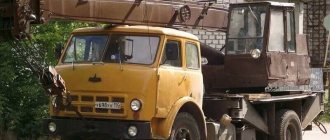
In the early 80s of the last century, on construction sites and in production, where it was necessary to move heavy weights and large-sized products, transport crane devices with a three-axis and four-axis design began to appear, in which the manufacturing principles of foreign manufacturers of technical equipment were visible, but on the boom device there were Russians the inscriptions are “January” and “Dnepr”. This is how the KS 5473 truck crane, developed in the late seventies, appeared on the transport market.
From the history of Dnepr truck cranes...
The transport had a lifting capacity of twenty-five tons and was equipped on a special three-axle chassis, which had high speed properties and good maneuverability. These cranes began to be produced en masse by the Odessa crane plant, together with the Polish transport workers Bumar-Fablok. In Poland, such a crane mechanism was given the name DS-0253T. After some time, the production of this equipment moved from the Odessa district to the Nikopol plant for the production of special equipment.
The first batches of cranes were equipped with Polish diesel engines, but as it turned out, after the service life was exhausted, engine repairs were associated with the supply of spare parts from Poland. However, this operation was carried out with long delays, which led to long downtime of the crane mechanisms. Therefore, many enterprises that had such crane units at their disposal began to replace Polish diesel with the domestic YaMZ brand. Over the past period, the KS-5473 device, also called the Dnepr truck crane, has undergone repeated modernization, new models have appeared - KS-5473B and KS-5473V, as a result of these works - the lifting capabilities of such technical transport have increased to 28 tons.
By design, the Dnepr truck crane is a hydraulic technique. The transport is equipped with a telescopic boom device. The drive force for all mechanical connections is provided by the diesel chassis. The crane mechanism has hydraulic support legs, but the device is endowed with the ability to perform all cargo operations without support, with a limited tonnage of lifting operations (eight tons). The design of this lifting mechanism includes two coupling hook elements with a strength of up to twenty-five tons of impact. Such elements are used in the operation of the main or additional lifting connection.
MANIPULATING CRANES, CMU UNITS, TRUCK CRANES
_____________________________________________________________________________________________
Review of the KS-5473 Dnepr truck crane
The KS-5473 Dnepr truck crane with a lifting capacity of 25 tons is hydraulic with a telescopic boom driven by a diesel chassis. The crane is equipped with hydraulic supports, but can work without them with a lifting capacity of 8 tons. The truck crane is equipped with 25 and 5-ton hooks for the main and auxiliary lifting mechanisms. The KS-5473 Dnepr truck crane has a three-section telescopic boom that changes its length under load in accordance with the crane’s passport characteristics. An unsteered jib can be installed at the end of the third section. The truck crane is equipped with tower-boom equipment: the boom is brought into a vertical position and a 15-meter controlled jib is attached to its end. To change its reach, an additional winch is provided. Winches, a turning mechanism, a control cabin and a counterweight are mounted on the turntable. The crane mechanisms are controlled from the platform cabin, and movement is controlled from the chassis cabin. The running device is based on a three-axle special chassis PS-253 with two rear driven axles and one steered front axle, equipped with 14.00-20 tires. The chassis and hydraulic motors of the crane mechanisms are driven by a YaMZ-236 diesel engine.
Characteristics of the KS-5473 Dnepr truck crane Load capacity, t - with the smallest hook reach - 25 - with the greatest hook reach - 7 - when moving with a load - 8 Boom length, m: - with the telescope retracted - 10 - extended - 22.6 Hook reach, m - smallest - 3.2 - largest - 8 Speed of lifting and lowering the hook, m/min - 0.33...19.3 Weight of the KS-5473 truck crane in working condition, t - 27.8 Maximum lifting capacity, t: - on remote supports - 25 - without outriggers - 5 Minimum reach, m - 3.2 Maximum hook lifting height, m: - on the main boom - 10 - on an extended boom - 22.6 - with additional equipment (extension and jib) - 36 Number boom sections, m - 8 Length of boom extension KS-5473, m - 8 Jib length, m - 7 Highest speed of lifting (lowering) load, m/min - 11.6/36 Highest rotation speed of the crane platform, per minute - 1, 0 Time of full extension of the boom, s — 70 Time of change in hook extension, s — 48 Overcome slope of the track, degrees — 15 Highest speed of movement, km/h: — transport — 60 — working — 2.5 Dimensions of the support contour of the outriggers, m — 4.8×5.2 Smallest turning radius, m — 11.5 Engine power, kW — 149 Overall dimensions in transport position, m: — length — 12.0 — width — 2.5 — height — 3.6 Truck crane weight with the main boom, t - 28 Operations with replaceable equipment of the KS-5473 Dnepr truck crane Transferring the jib of the KS-5473 truck crane from the transport position to the working position To transfer the jib from the transport position to the working position, it is necessary to unfold the jib from the fixed position along the boom and dock it with its base to the boom head. Perform the transfer in the following sequence: — install the crane on outriggers; — release the main hook suspension from engagement; — retract all sections and install the boom of the KS-5473 truck crane in a horizontal position; — place it on the working platform with the main hook suspension; — remove the wedge clip with the cargo rope from the boom head; — disassemble the clamp on the wedge clip and remove the cargo rope from it; — knock out the wedge from the wedge holder; — remove the cargo rope from the wedge holder; — unfasten the cargo rope and dismantle the hook suspension; — remove the six fingers with clamps from the forks at the base of the jib; — unlock the block in the jib head of the KS-5473 Dnepr crane and install it in the “upper” working position, then fix it in this position using a pin with a lock; — remove the lock and remove the pin from the bracket on the boom; — using a mounting strap tied to the jib head, remove the jib from the bracket on the boom and move the jib head away from the base of the boom; — ensure alignment of the holes on two axes in the boom head (on the right side in the direction of travel of the crane) with two corresponding holes in the forks of the jib base; — insert fingers into the aligned holes and secure them with clamps; — remove the pin connecting the bracket in the jib head and the boom bracket; — using a mounting strap tied to the jib head, remove the jib from the boom bracket and slowly rotate the jib 180°; — align the holes in the axes of the KS-5473 boom head (on the left side in the direction of travel of the crane) with the corresponding holes in the forks installed on the jib base brackets; — insert fingers into the aligned holes and secure them with clamps; — next to the already fixed fingers (on the right side in the direction of movement of the crane), also install fingers with clamps in adjacent aligned holes; — check the straightness of the installation of the jib on the boom (the flanges of the block in the head of the jib should not extend beyond the lateral visual lines, which are a continuation of the width of the base of the boom); — insert the cargo rope into the jib base block (already in the “upper” working position) and install an axle with a lock on the block; — insert the cargo rope into the block on the jib head of the KS-5473 Dnepr truck crane and install the axles with clamps on the block; — move the lift height limiter from the boom head to the jib head, having first disconnected the plug connector on the boom head (put the load rope into the lift height limiter bracket); — connect the electrical cable installed on the jib through the plug connectors to the cable on the boom head and to the lift limiter on the jib; — secure the end of the cargo rope in the wedge cage; — connect the wedge cage with the auxiliary hook suspension; — raise the boom and fully extend the boom sections, ensuring that the auxiliary hook suspension is located in the working area; — set the appropriate operating configuration of the load limiter; - turn on the lifting mechanism from the crane operator’s cabin to the “lifting” operation and slowly raise the auxiliary hook suspension 1-1.5 m from the surface, then leave it in this position and wait until the load rope is completely untwisted; — wrap the rope with a working load; Changing the inclination angle of the jib of the KS-5473 Dnepr truck crane. Changing the inclination angle of the KS-5473 jib to the 30° position is performed in the following sequence: - install the crane on outriggers; — rotate the working equipment to a position of 180° from the chassis cab; — lower the boom with the jib to a position that provides access to the boom head from the working platform, but without allowing the jib head to touch the surface of the working platform; — lower the auxiliary hook suspension onto the working platform; — disconnect the plug connector on the boom head and remove the lift height limiter installed on the jib head; — remove the auxiliary hook suspension from the cargo rope; — remove the axles from the jib blocks, which secure the cargo rope from possible falling out of the block stream; — remove the cargo rope from the jib blocks; — secure the wedge clip to the head of the jib and, using the lifting mechanism, pull the cargo rope; — remove the fixing pin from the junction of the rod with the jib; — lower the jib using the lifting mechanism of the KS-5473 crane to a position at which it is possible to connect the rod with the jib; — install a finger to fix the jib in a tilt position relative to the boom axis at an angle of 30°; — remove the wedge clip from the jib head; — insert the cargo rope into the jib blocks and install the axles with clamps; — install the lift height limiter and connect the plug connector on the head; — connect the cargo rope to the auxiliary hook suspension; — set the load limiter to the appropriate operating configuration; — lift the boom of the KS-5473 truck crane with a jib to a height of 1-1.5 m and make sure of the strength of the assembled structure; — working with the appropriate joysticks in the crane operator’s cabin, slowly raise the boom with the jib at an angle of 45-60°; — using the lifting mechanism, slowly raise the auxiliary hook suspension to a height of 0.5-1.0 m from the surface and wait until the cargo rope is completely untwisted; — pull up the auxiliary hook suspension to the jib head; — check the correct operation of the lift height limiter. After completing the above operations, the Dnepr truck crane is ready to work with the jib set to the 30° position. Changing the angle of inclination of the jib of the KS-5473 Dnepr crane from a position of 30° to 0° should be done in the following sequence: - install the crane on outriggers; — rotate the working equipment to a position of 180° from the chassis cab; — lower the boom with the jib to a position that provides access to the boom head from the working platform, but without allowing the jib head to touch the surface of the working platform; — lower the auxiliary hook suspension onto the working platform; — disconnect the plug connector on the boom head of the KS-5473 Dnepr and remove the lift height limiter installed on the jib head; — remove the auxiliary hook suspension from the cargo rope; — remove the axles from the jib blocks, which secure the cargo rope from possible falling out of the block stream; — remove the cargo rope from the blocks; — secure the wedge clip to the head of the KS-5473 jib and pull the cargo rope using the lifting mechanism; — remove the fixing pin from the junction of the rod with the jib; — use the lifting mechanism to raise the jib to the 0° position, at which it is possible to connect the rod with the jib; — set the finger to fix the jib in the tilt position relative to the boom axis at an angle of 0°; — remove the wedge clip from the jib head; — insert the cargo rope into the jib blocks and install the axles with clamps; — install the lift height limiter and connect the plug connector on the head of the KS-5473 truck crane; — connect the cargo rope to the auxiliary hook suspension; — set the load limiter to the appropriate operating configuration; — lift the boom with the jib to a height of 1-1.5 m and make sure the strength of the assembled structure; — working with the appropriate joysticks in the crane operator’s cabin, slowly raise the boom with the jib at an angle of 45-60°; - using the lifting mechanism, slowly raise the auxiliary hook suspension to a height of 0.5-1.0 m from the surface and wait until the cargo rope is completely untwisted. Transferring the jib of the KS-5473 Dnepr crane from the working position to the transport position To transfer the jib of the KS-5473 truck crane from the transport position to the working position, you must do the following: - install the crane on outriggers; — rotate the working equipment to a position of 180° from the chassis cab; — lower the boom with the jib to a position that provides access to the boom head from the working platform, but without allowing the jib head to touch the surface of the working platform; — lower the auxiliary hook suspension onto the working platform; — disconnect the plug connector on the boom head of the KS-5473 Dnepr and remove the lift height limiter installed on the jib head; — remove the auxiliary hook suspension from the cargo rope; — remove the axles from the jib blocks, which secure the cargo rope from possible falling out of the block stream; — remove the cargo rope from the blocks, after which the axles on the blocks are put in place; — remove from the holes in the axles on the boom head (on the right side in the direction of travel of the crane) the pins with clamps connecting the boom brackets to the forks of the jib base; — remove from the holes in the axles on the boom head (on the left side in the direction of travel of the crane) the pins and clamps connecting the boom brackets to the forks of the jib base; — using a mounting strap tied to the head of the jib, rotate the jib 180°; — ensure that the holes in the jib bracket and the boom bracket are aligned, and then install the pin in the aligned holes; — install the jib on the boom base bracket KS-5473; — remove the pins with clamps from the holes in the axes of the boom head (on the right side in the direction of travel of the crane); — using a mounting strap tied to the jib head, bring the jib head close to the base of the boom; — install the finger in the bracket on the boom (at the junction of the boom with the jib head) and fix it; — unlock the block in the jib head and set it to the “lower” non-working position, and then fix it in this position; — insert the fingers with locks into the forks at the base of the jib; — place the auxiliary hook suspension in the basket on the boom support stand; — install the lift height limiter on the boom head KS-5473 and connect its cable to the plug connector block on the boom head; — store a cargo rope using the main hook suspension and blocks in the boom head (put the last two branches of the pulley into the lifting height limiter load brackets); — secure the end of the cargo rope in the wedge clip, and install the wedge clip on the boom head; — wrap the cargo rope with the working load; — check the correct operation of the lift height limiter.
_____________________________________________________________________________________________
_____________________________________________________________________________________________
- Main equipment and parameters of Unic CMU
- Operation of the Unic crane installation
- Palfinger CMU design
- Palfinger manipulator overload protection system
- CMU Hiab 190
- Hiab XS 320 loader crane
- Hiab 100/120 hydraulic manipulator
- CMU Tadano
- CMU Amco Veba
- KMU Fassi
- CMU Dongyang SS1506
_____________________________________________________________________________________________
- Equipment KS-35714
- Hydraulic system KS-35714, KS-35715
- Equipment and mechanisms KS-3577-4
- Recommendations for repairing KS-3574
- Hydraulic equipment KS-55713
- Repair of telescopic boom KS-55713-1K-3
- Parts and mechanisms of the rotating part KS-45717-1
- Design and controls KS-4572, KS-45719
- Operation of hydraulic equipment KS-45721, KS-45715
- Device KS-55727
- Review of the KS-6476 design
- Maintenance of KS-3579
- Adjustments KS-35719
- Truck crane KS-3575
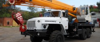
- Crane KS-5576 Ivanovets
- Truck crane KS-5473 Dnepr
- XCMG QY25K5S truck crane
- Crawler crane MKG-25 BR
- Repair of chassis DEK-251
- Crane RDK-250
What is a crane boom?
The construction of the boom of a truck crane has its own characteristics. It is a three-section telescopic mechanism capable of changing its size under the influence of the mass of the load, which is specifically stipulated in the certificates on the characteristic properties of transport. The design of the boom device provides for the possibility of installing a jib, without further direct control.
If the technical device of the truck crane is equipped with tower boom components, the boom device can be pulled out vertically, while a controlled jib of fifteen meters in size is attached to the end of the boom. Its extension is changed using an additional winch. The base and retractable sections of the boom are made in the form of welded steel structures. The boom extension mechanism comes in two types: either one long-stroke hydraulic cylinder and two rope pulleys, or a second hydraulic cylinder is installed instead of a rope pulley.
The boom is installed on a movable platform base; winch elements, a rotary gearbox of the truck crane, counterweight components and a control compartment are also mounted here. Crane equipment is controlled only from the operator sector located on the main platform; the movement of the device can be controlled by the operator sector of the chassis.
The Dnepr truck crane received a solution for running moments in the form of a three-axle special chassis PS-253, which has two rear drive axles and one steered front axle. The chassis and hydraulic motors of the crane mechanisms are driven by a YaMZ-236 diesel engine. The native Polish engine has long been forgotten.
| Crane KS-5473 on a special automobile-type chassis description and technical characteristics |
The KS-5473 crane with a lifting capacity of 25 tons is hydraulic with a telescopic boom driven by a diesel chassis. The crane is equipped with hydraulic supports, but can operate without them with a lifting capacity of 8 tons. The crane is equipped with 25- and 5-ton hooks for the main and auxiliary lifting mechanisms.
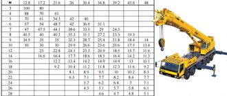
| Crane KS-5473 with replaceable boom equipment and its cargo (solid lines - on outriggers, dotted line - without outriggers) and height (dash-dotted line) characteristics: a - crane with a boom 24 m long, b - the same, with an 8 m extension , c - the same, with an uncontrolled jib, d - the same, with an extension of 8 m and an uncontrolled jib of 7 m, 1 - 4 - with a boom length of 10, 15, 20, 24 m, respectively; 5 - the same, 24 m with an extension or uncontrolled jib 8 m, main lift; 6 — the same, auxiliary lift; 7 - with a boom 24 m long with an uncontrolled jib 8 m, auxiliary lift; 8 - with a boom 24 m long with an extension of 8 m and an uncontrolled jib of 7 m, main lift; 9 - the same, auxiliary lift. |
The crane has a three-section telescopic boom that changes its length under load in accordance with the crane's passport characteristics. An unsteered jib can be installed at the end of the third section. The crane is equipped with tower-boom equipment: the boom is raised to a vertical position and a 15-meter controlled jib is attached to its end. To change its reach, an additional winch is provided. Winches, a turning mechanism, a control cabin and a counterweight are mounted on the turntable. The crane mechanisms are controlled from the platform cabin, and movement is controlled from the chassis cabin. The running gear is designed in the form of a three-axle special chassis PS-253 with two rear drive axles and one steered front axle, equipped with 14.00 - 20 tires. The chassis and hydraulic motors of the crane mechanisms are driven by a YaMZ-236 diesel engine.
Technical characteristics of the KS-5473 crane
| Loading capacity, t, of the main hook: | |
| .on supports: | |
| ..at the smallest hook reach | 25 |
| ..at maximum hook reach | 9 |
| ..when telescoping (largest) | 9 |
| .without supports: | |
| ..at the smallest hook reach | 8 |
| ..at the smallest hook reach when moving | 8 |
| Loading capacity of auxiliary hook, t | 5 |
| Hook reach, m: | |
| ..least | 3,5 |
| ..greatest | 9 |
| Hook lifting height, m: | |
| ..at the smallest offset | 10 |
| ..at maximum reach | 4 |
| Speeds: | |
| ..lifting the main hook, m/min | 8,5 |
| ..lowering, m/min | 0,25 |
| ..platform rotation speed, rpm | 0,1 — 1,5 |
| ..crane movement, km/h | 2,5; 60 |
| Power, hp, of the running gear engine | 205 |
| Wheel track, m: | |
| ..front | 2.25 |
| ..rear | 1,95 |
| Crane weight, t | 28 |
| Photo gallery of cranes on a special chassis KS-5473 |
| Back to the page “Cranes. Descriptions and technical specifications" |
| The author of the site would be grateful for any information and photographs. Email |
| Copyright © 2002-2016 TechStory.ru |
home
Truck crane Dnepr technical characteristics of the model KS 5473
In the early 80s of the last century, on construction sites and in production, where it was necessary to move heavy weights and large-sized products, transport crane devices with a three-axis and four-axis design began to appear, in which the manufacturing principles of foreign manufacturers of technical equipment were visible, but on the boom device there were Russians inscriptions – “January” and “Dnieper”. This is how the KS 5473 truck crane, developed in the late seventies, appeared on the transport market.