Renault engines for the Russian auto industry
The Russian auto industry has long demanded a modern 6-cylinder in-line diesel engine.
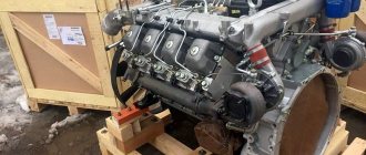
And very soon he will appear. On June 19, 2006, an event occurred in Yaroslavl that put an end to the negotiations between GAZ Group and Renault Trucks that had lasted for almost a year. Igor Kulgan, Director of the Engines Division, and Stefan Shmilevsky, President of Renault Trucks, signed a contract under which GAZ Group acquires a license for the Renault dCi11 engine and its production line, which will be moved from Lyon to Yaroslavl to the Avtodiesel production site "(Yaroslavl Motor Plant). The dCi11-11-liter in-line six diesel engine with a common rail injection system complies with Euro 3 standards, which are introduced in Russia from January 1, 2008. Its maximum power is 303 kW (412 hp). Renault Trucks installed the dCi11 on its medium and heavy trucks and produced approximately 1 million vehicles with it, which demonstrates the merits of a proven, reliable and technologically advanced engine design. Bringing a diesel engine to Euro 4 level does not present any technical or financial difficulties. Currently, the dCi11 has been discontinued and replaced by the latest generation diesel engine, the dXi11, with characteristics that exceed current European emissions standards. Production of dXi11 is launched at a state-of-the-art plant near Lyon.
The acquisition of a license for the production and modernization of dCi11, and GAZ Group intends to bring it to Euro 4 level, is in line with the group’s strategy until 2011 and involves the creation of a line of Euro 3 and Euro 4 in-line engines. Production and development of the existing line of engines will continue. In the future, Avtodiesel intends to produce a full range of engines from medium and even light to super-heavy.
According to the contract, by the fall of this year the production equipment will be dismantled and moved to Yaroslavl, and this work has already begun. GAZ Group has refused some of the equipment and intends to purchase new, more modern and productive ones, taking into account its use in other projects. In the second half of 2007, it is planned to produce several dozen or hundreds of engines, depending on the readiness of production for their certification and testing on cars of the main consumers - cars that are part of the GAZ Group, the Kremenchug Automobile Plant and the main customer of YaMZ engines - the Minsk Automobile Plant. Starting from the summer of 2008, it is planned to begin mass production of at least 18 thousand engines per year, which will ensure the economic efficiency of the project.
Renault Trucks will conduct training for our specialists - engineers, mechanics, technicians who will install and work on this equipment. Training will begin on September 1. Together with Avtodiesel specialists, representatives of Renault Trucks will begin to control the quality of manufactured engines.
The deal seems interesting for both parties. The French side sold the rights to intellectual property and added the freed-up assets - the production line. In addition, Renault Trucks has acquired a long-term partner with influence over a vast territory.
The benefits for the Russian side are more complex and multifaceted. GAZ Group acquired a full package of rights to the engine, including its modernization. The possibility of fine-tuning the existing family of Yaroslavl diesel engines to comply with Euro 4 standards seems doubtful, and there is no time to develop our own dCi11 level unit from scratch; it has long been hopelessly lost. In such cases, purchasing a license is a civilized and common way to overcome the backlog, especially since Yaroslavl already has experience in licensed assembly of GMC engines (1946). The license gives GAZ Group not only a gain in time, modern designs and technologies, but also a powerful impetus for development, which will ensure the competitiveness of the group until 2014.
| The President of Renault Trucks was interested in Avtodiesel products |
The contract amount - 57 million euros - was described by the parties to the transaction as a “good price”, and all the “advantages” of this price are more visible in the price of the engine for sales in Russia, which is planned at 8.5 thousand euros - 1.5. 2 times cheaper than analogues. By the way, this was one of the reasons why GAZ Group chose Renault Trucks as a partner.
This project initiates related and significantly larger projects related primarily to the localization of production - new opportunities for growth in the domestic mechanical engineering industry. The project provides for the production and machining of the block head and connecting rod group. The remaining components, including castings, will be supplied by partners Renault Trucks. The problem of locating a foundry both for engine production and for the needs of the entire GAZ Group within the country is being studied, but so far there is no reason for optimism - there is no ready-made production that provides the required level of quality. As these types of problems are solved, the degree of localization will increase. It is possible that GAZ Group itself will become a supplier to Renault if it achieves a better price/quality ratio than its competitors. Thus, the GAZ Group will become part of the global economy, part of the global automotive industry.
The implementation of the project will allow us to gain experience working with the Common Rail injection system, which is not yet used in Yaroslavl. The GAZ Group has already clearly determined that the future of its engines is Common Rail, but has not yet decided which path it will take - whether it will deal with the injection system independently or in partnership with any world-class company. Further developments will depend on this decision.
| “Will the city be founded here?” |
In a fairly short time, it is necessary to decide on transmission units - buy them, develop your own, buy a license, etc. It is known that negotiations are underway with Renault Trucks, but neither side has made official statements. There was also no information about the number of personnel that will be involved in the project, but GAZ Group assured the regional administration that it will certainly create new jobs. Related projects will also require additional labor.
In addition, GAZ Group must create an extensive infrastructure for service and repair of dCi11 engines and subsequent models.
RENAULT ENGINES
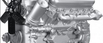
To put it mildly, this statement is not entirely correct. Suffice it to say that engines for both Renault Trucks and Volvo Trucks are currently produced at a plant in France. The previous generation power unit, DCI, was also produced there. During its existence on the assembly line in France, this engine has evolved from a motor with a mechanical fuel injection pump to an electronically controlled unit that complies with Euro-3 standards. This motor was produced from 1997 to 2007, but the veteran’s biography did not end there. Its production line is currently operating in Russia at the Yaroslavl Motor Plant.
And at the plant in France it was replaced by a new power unit of the DXI 11 series, which indeed, with minor changes, is installed on both Renault and Volvo trucks.
Dump trucks and truck tractors equipped with both power units are found on Russian roads in large quantities. A worthy reason to get to know these engines in more detail!
WHAT'S IN YOUR NAME?
The full name of the previous generation engine looks something like this:
DCI 11 C+J01 Where “DCI” stands for diesel engine with COMMON RAIL accumulator injection system;
“11” - engine displacement in liters;
“C” means, firstly, that the engine has several versions with different power. Secondly, the power of this particular engine is 420 horsepower. Accordingly, the letters “E”, “G”, “I” mean power equal to 370, 320 and 270 horsepower;
“J01” is a designation for environmental regulations. More precisely, not the norms themselves, but the month and year when they came into force.
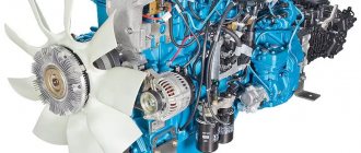
The engine itself is a six-cylinder, in-line, with a solid cylinder head, inside of which there is a “return”, and four valves per cylinder. And since its design dates back to the end of the 20th century, the valves are driven through pushers and rocker arms. This circumstance did not prevent many engines from being equipped with a motor decompression brake. The timing gears and fuel pump are traditionally located in the front of the engine.
The fuel pump, which creates high fuel pressure in the rail, is located in place of the old injection pump. Two high-pressure tubes extend from its two sections into the ramp. From the ramp, fuel is distributed to the injectors. The fuel supply circuit to the engine is as follows: a fuel tank, an optional separator filter, a cooling circuit of the electronic control unit, a fuel priming pump with a small coarse fuel filter, a low pressure section in the injection pump, fine filters and the injection pump itself.
Two fine fuel filters are located closer to the flywheel. After replacing them, it doesn’t hurt to bleed the system. To do this, unscrew the plug and screw the bleeder fitting onto one of the filters as shown in the photo. Otherwise, the mixture of air and fuel will simply circulate through the system. To bleed, you need to use the handle on the body of the fuel priming pump. It is located closer to the high pressure pump. You don't need to touch anything else.
In conventional high-pressure fuel pumps, if anyone remembers, there was a pressure-limiting valve in the discharge cavity. And since there was little pressure there, it had a rather weak spring and could open and close an infinite number of times, releasing excess fuel into the return line. The high pressure rail also has a similar valve, but it works differently. The pressure in the ramp is not low, but high. And in the case of “normal” operation of all components of the fuel system, the pressure in it will not exceed the norm. This is monitored by an electric pressure sensor. As a last resort, this valve opens, relieves pressure and closes. After this, it requires replacement, since it may not close completely. This is not a “disease” of the machine, it was designed from the very beginning. We can recognize that the “check” valve is not completely closed by the hot drain pipe coming from it.
Concluding a short tour of the fuel system, I convey a reminder to the technical staff of Renault Trucks. The voltage in the engine control system can be around 80 Volts. For example, it comes to the injector coils from the capacitor. This is one of the reasons why it is not recommended to try to disconnect or connect something while the engine is running. The pressure in the fuel system is an order of magnitude greater than in systems with a mechanical injection pump. Even a thin stream of high-pressure fuel penetrates the skin and causes severe inflammation - that's the minimum. If you get it in the eye, everything is much more fun.
Why do we write about such basic things? They seem elementary to “experienced” drivers. But quite often you come across either “riders” who are confident that “the car pumps itself, you need to crank the starter longer,” or maniacs who unscrew all the pipes, including the high pressure ones, in order to bleed the air from the ramp.
THE MAIN THING IS CULTURE
There are many examples of unskilled actions when servicing an engine.
It seems that the engine has a purely “mechanical” background; it does not have many complex bells and whistles such as recirculation, urea and an adjustable turbine. Therefore, many users of Renault Trucks manufactured before 2007 and MAZ trucks equipped with almost the same engine seem to be able to handle it easier than with the latest “foreign” engines. This is wrong. Let's take the oil system. Few people think that in addition to the traditional lubrication points for Soviet engines, oil is also supplied to the nozzles that direct it to the bottom of the piston. The oil channels run through the ribs of the engine block and in the head, and they are not very wide.
Just 2 days ago, one of my friends, who operates a foreign cargo truck, proudly announced that he had bought a friction modifier and intended to add it to the oil. And where did he get it? After all, the time for such products passed 10 years ago. It was with difficulty that I persuaded him to consult the servicemen about this. I wonder how long it would take before the miracle drug clogged the oil channels? When would a turbocharger fail, when would the pistons burn out?
The fuel system is the same. Any particle that a conventional fuel injection pump could digest without problems could prove fatal to the COMMON RAIL system. Therefore, special attention is paid to the quality of fine filters. And the left coarse fuel filter may not allow a sufficient amount of fuel to pass into the low-pressure section of the injection pump, which will result in abnormal engine operation under heavy loads and subsequent damage to the high-pressure equipment.
And, of course, since the entire engine is under the control of an electronic control unit, a lot depends on the operation of numerous sensors. The failure of some of them does not lead to the engine stopping; without others, work is impossible. With some malfunctions, it is simply impossible to increase the speed. For example, without the much-loved tachograph, you won’t be able to have a great ride. Having received a signal about its malfunction (or if the speed sensor on the gearbox is faulty), the engine control unit does not allow the engine to develop revolutions above 1200. If the gas pedal (and it is also electronic) breaks down, the revolutions are set to 900. When the engine brake is applied, the engine will not leave idle speed . It will also be impossible to start the engine if the stop button in the engine compartment is damaged or accidentally activated.
A malfunction of the coolant temperature sensor will cause the control unit to focus on the oil temperature. If the charge air temperature sensor malfunctions, the system will assume its temperature is 60 degrees. If the crankshaft speed sensor is damaged, the cyclic flow will be reduced by 20 percent, and if there is no signal from the fuel injection pump sensor, the engine will continue to operate, but starting it will be difficult. As with any other electronically controlled motors with DCI-11, you should be careful when performing repair work and monitor the integrity of the electrical connections during operation.
In general, the engine is very reliable and perfect.
For example, it does not have any coolant hoses, the thermostat and water pump are combined, and normal belts and automatic tensioners are used in the generator and power steering drives. It seems that this engine will last for many years to come on vehicles in use on Russian roads. Share
Tightening torques dxi 11
Replace the cylinder head mounting screws.
Do not wash off the bolt coating.
There must be no coolant, water or oil in the blind holes (risk of corrosion and cracking).
- Drain the coolant.
- Drain the engine oil.
- Remove the catalyst.
- Remove the intake manifold.
- Disconnect all plug connections from the cylinder head.
- Remove the cylinder head cover.
- Remove the control units on the intake side and exhaust side.
- Remove the right solenoid valve.
Remove the ground jumper on the screw (1).
Release screw (1).
Unlock the engine crankcase ventilation system (3) in the direction of the arrow and remove it towards the front.
- Release metal clamps using special tool 17 2 050.
The coolant temperature sensor is installed at the rear of the cylinder head in the outlet flange of the cooling system.
Unlock and disconnect connector (1).
Squeeze the locking tabs on the coolant temperature sensor (2). Pull it back out of the cooling system flange and remove the coolant temperature sensor (2).
Release screw (1).
Unscrew the nut (1).
Remove the heat shield (2) upwards.
Remove screws (1).
Remove screw (2).
Release screw (1).
Remove the support (2) with the heat shield and the catalyst holder.
Release screw (1).
Disconnect the coolant pipe (2) from the exhaust turbocharger.
Replace the O-rings.
Replace the O-ring.
Release screw (1).
Disconnect the oil supply line with a suitable tool.
Replace the O-ring.
Release screw (1).
Disconnect the oil drain line (2) using a suitable tool.
Replace the O-ring.
Loosen the band clamp (1).
Disconnect the oil drain line (2).
Unscrew the hollow screw (3).
Remove the oil supply line (4).
Replace the O-ring.
Place special tool 13 0 250 (1) onto the fuel supply line (3), placing the locking lugs of the tool in the grooves of the quick release coupling.
Secure special tool 13 0 250 over the knurled screw (2).
Place a cloth over the fuel supply line and high pressure pump.
To unlock, move the fuel supply line (3) towards the high-pressure pump, then remove it in the direction indicated by the arrow.
Remove special tool 13 0 250 and a cloth.
Close the high pressure pump fuel line connection using a suitable plug.
Seal off the fuel supply line using special tool 13 5 161.
The fixing tabs must be undamaged. A fuel line with damaged retaining tabs must be replaced.
The fuel supply line should click into place with an audible click.
If the timing chain in the timing block is removed from the sprocket, the crankshaft can no longer be turned.
It is possible to clamp the drive chain using the crankshaft gears.
The drive chain can only be pulled out using the hook during assembly.
Release screw (1).
Unscrew the cylinder head bolts using special tool 11 2 250 .
Remove the cylinder head bolts from the edges to the middle (10 to 1).
Remove the spacer washers using a magnet.
Drawing without camshaft.
Lift the cylinder head using a crane or have an assistant present.
The weight of the cylinder head with exhaust turbocharger is approximately 35 kg.
Remove small sealant residues using special tool 11 4 472.
There must be no coolant, water or oil in the blind holes (risk of corrosion and cracking).
Clean all blind holes using a suitable tool.
Replace the cylinder head mounting screws.
Do not wash off the bolt coating.
Place spacer washers on the cylinder head bolts.
There is a possibility of the spacer washers falling into the engine (risk of damage!).
Tighten the bolts (1 to 10) securing the cylinder head from the middle to the edges.
It is necessary to strictly follow the sequence of actions when removing and installing the exhaust camshaft
The upper and lower support bars must be secured with a total of six fixtures 11 4 461 .
Remove the exhaust camshaft control unit.
Adjust valve timing.
| Remove the bolts securing the bearing caps from the edges to the middle. |
Remove the lower and upper support bars (1) with the camshaft upwards.
Remove the upper support bar (1).
Remove the exhaust camshaft from the lower support bar.
| Warning! |
The markings on both camshafts are different.
Installing camshafts in the wrong place will cause engine damage.
.
A Exhaust camshaft.
E Intake camshaft.
| Check rectangular rings (1) for damage and replace if necessary. |
Rings (1) of rectangular cross-section are snapped into place at the joint.
Unfold the rectangular ring (1), one end up and the other end down, and remove it forward.
The rectangular rings (1) break easily.
| Warning! |
Removal on the engine:
Set the engine to the TDC position of the 1st cylinder.
Removed cylinder head:
When using tool 11 9 000, the aluminum spacer must be removed.
| Installing the camshaft support bar: |
Pre-install special tool 11 4 462 on cylinder 2.
Insert special tool 11 4 463 into cylinder head cover mounting hole
Special tool 11 4 463 is a special screw.
Press the roller tappet lever (3) of the 2nd cylinder with the spindle nut (2) of special tool 11 4 462 .
| When installing: |
Before installing the exhaust camshaft, pay attention to the position of the valve and the roller tappet arm on the HVA element!
Refer to Removing and Installing Roller Tappet Arms.
| Place the lower support bar (1) with the exhaust camshaft (2) onto the roller tappet arms. |
Install the exhaust camshaft (2) in place.
Cylinders 2 and 4 are on overlap.
The cams (3) of the first cylinder are located obliquely upward.
The registration number (4) on the flat points upwards.
| Tighten the exhaust camshaft bolts with the lower and upper support bars (1) using a torque wrench (2) from the middle to the edges to a torque of 8 Nm . |
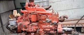
DXI 11 cylinder block from the Renault Premium model in Tyumen
Warranty terms
All used parts come with a INSPECTION AND INSTALLATION WARRANTY . That is, if after installation the spare part works properly (spins, turns, starts), the warranty obligations from the Seller are removed.
Warranty period: 3 calendar days from the date of receipt. Complex expensive components and assemblies (engine, gearbox, gearbox...) are covered by an extended warranty: 14 calendar days .
Return Policy
The buyer DOES NOT have the right to return the product or demand a replacement in the following cases:
- the product is not the cause of the vehicle malfunction;
- after 3 days from the date of purchase;
- the product is not complete in the form in which it was purchased;
- the product has been opened or repaired without authorization;
- departmental marks, seals, etc., if any were supplied by the seller, have been broken;
- the product does not correspond to the overall dimensions, color, or smell previously agreed upon with the Seller.
The malfunction of the product must be confirmed by an order from the service center describing the reason for the malfunction of the spare part or, if possible, checked by our mechanics at the warehouse.
If a defect in the product is discovered after purchase, the Buyer may be reimbursed for the cost of restoration work. The cost of repair services for defective goods, subject to reimbursement, must be agreed upon with the Seller before the repair is carried out.
In the event of returning a technically faulty product, the Buyer delivers it to the auto disassembly warehouse at its own expense or on its own, and the Buyer is not reimbursed for the cost of installation work.
In some cases, goods that do not fall under the terms of the warranty return, by agreement with the Seller, may be left for sale with a deduction of 10% of the sale price of the goods.
Pickup point in Tyumen
Russia, Tyumen, Tobolsk tract 13 km, 1k1 (parking area of the Transit Hotel)
Mon - Fri: from 09 to 18 o'clock, lunch from 13 to 14 o'clock Sat, Sun: closed.
Spare parts are sent (ordered by a forwarder to pick up the cargo) only after 100% payment on the invoice !
We will deliver spare parts for your truck to any region of Russia .
Spare parts whose weight or dimensions preclude manual loading into the vehicle are transported using a manipulator, the services of which are paid for by the buyer.
Urgent dispatch of a spare part by our company’s employees to the warehouse of a transport company or accompaniment of the manipulator with the registration of a technical specification costs 1000 rubles.
You can pay for the spare part you have chosen using the chosen method:
- Cash in the office;
- By card through the terminal to the office;
- By non-cash payment (without VAT!) as a legal entity;
- Online transfer to a card from Sberbank, Alfa-Bank, VTB.
Contents Operating instructions Renault Premium DXI 11
CONTENTS OF THE BOOK OPERATION AND MAINTENANCE MANUAL RENAULT PREMIUM DXI 11 370 / 410 / 540 / 330 / 380 / 440
PREFACE 7 General requirements 7 Pre-trip requirements 7 Driving requirements 8 Parking requirements 8 Vehicle repair and maintenance requirements 8 Warranty requirements 10 OPERATING INSTRUCTIONS 11 VEHICLE ACCESS AND SECURITY 11 Keys 11 Doors without central locking 12 Doors with central locking 13 Electric Battery Switch 15 Cab and Step Lights 15 Security Alarm 16 EXTERIOR EQUIPMENT 19 Fascia 19 Windshield Access 20 Side Skirts 20 Cab Tilting 21 External Storage Compartments 24 Fuel Tanks 25 Battery Switch 27 CAB EQUIPMENT 2 8 Seats 28 Instrument panel 33 Instrument cluster 34 Tachograph 35 Icons 37 Switches 42 Advanced and basic multi-information displays 44 Secondary menu 47 Main menu 48 Multi-information display ECO 58 Secondary menu 59 Main menu 61 Electrically operated rear view mirrors 67 Heated windshield 68 Combination light switch ov and sound signal 68 Steering wheel adjustment 70 Parking brake 71 Electric windows 72 Sunroof 73 Heating and ventilation 74 Programmable auxiliary heater 80 WEBASTO auxiliary heater 83 Bunks 84 Luggage sections 86 Cab overhead lights 92 Refrigerator 92 On-board radio 93 Compressed air bleeder 94 SECURITY 95 Seat belts 95 Fire extinguisher 96 Wheel chocks 97 ADR vehicle 97 PREPARATION FOR DRIVING 101 Run-in 101 Winter or cold climate operation 101 Summer or hot climate operation 102 Dusty operation 102 High altitude operation 102 Economy new driving 102 Driving a tractor without a trailer 102 Preheating the engine cooling system 102 Before driving 103 STARTING THE ENGINE 109 Before starting the engine 109 Starting the engine with a controlled starter 110 Engine idle speed control 111 Quick idle speed control 112 Power take-off (PTO) 113 VEHICLE ON THE MOVE 113 Hydraulic power steering 113 Engine speed 113 Cruise control 114 Electronic speed limiter 118 Accelerator pedal 118 Retarder 118 Control monitoring system (DMS) 124 Manual transmission 127 OPTIDRIVER+ transmission 128 EBS brake system 139 ESP system (program electronic stabilization) 142 Trailer brake 143 Parking brake 143 END OF MOVEMENT 146 Stopping the engine 146 Disconnecting the battery 147 DRIVING IN DIFFICULT TERRAIN 148 Locking the center differential 148 Locking the center differential 148 ASR (anti-slip system) 149 EQUIPMENT CONTROL 150 Working movable headlight (tractor) 150 Hitch 150 Rear suspension 155 PTO (power take-off) 161 Roof spoiler 164 Front view mirror 164 Monitoring/control equipment 165 MAINTENANCE 165 Vehicle identification plates 165 Daily checks 166 Replacing lamps 169 Adjusting headlights 175 Replacing fuses 179 Replacing battery remote control remote control 184 MAINTENANCE 184 Warranty conditions 184 Specification 187 Lubrication charts 190 Service intervals 193 Engine maintenance 198 Engine cooling system maintenance 203 Fuel system maintenance 207 Clutch maintenance 215 Gearbox maintenance 217 Hydraulic retarder maintenance 225 Maintenance of RTO ( Power Take-Off) 225 Transmission Maintenance 225 Front Axle Maintenance 225 Rear Axle Maintenance 227 Suspension Maintenance 229 Steering Maintenance 230 Cab Tilting Maintenance 232 Brake Maintenance 232 Wheel and Tire Maintenance 234 Heating and Air Conditioning Maintenance 239 Auxiliary Heater Maintenance 240 Battery Maintenance 240 Alternator Maintenance 244 Starter Maintenance 245 Air System Maintenance 245 Fifth Wheel Maintenance 246 Vehicle Cleaning 246 QUICK TROUBLESHOOTING 248 Jump Starting the Engine 248 Jack and Flat Kit Locations 248 Spare wheel holder 249 Jack 250 Wheel chocks 251 Tightening wheel nuts 252 Towing 253 BODY WORK 255 Body installation 255 Welding work on the vehicle 255 Soundproofing barriers 256
BUY BOOK OPERATION AND MAINTENANCE MANUAL RENAULT PREMIUM DXI 11 370 / 410 / 540 / 330 / 380 / 440
© Autoliterature 2008
All materials published on the website https://avtoliteratura.ru , photographs or texts, are subject to copyright. Trademarks and logos, as well as copyrights and related rights belong to their legal owners. Partial or complete copying of texts, slogans and photographs without the written consent of the site owners is prohibited and entails liability in accordance with current legislation
The main difference between our store and all other auto book stores is that we actually have in stock the automotive literature that is presented on the website