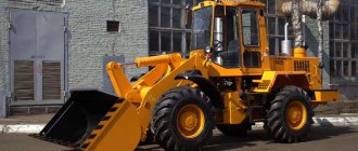
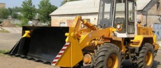
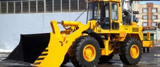
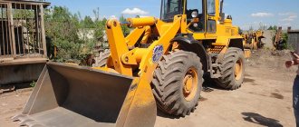
The uninterrupted and efficient operation of Amkodor loaders largely depends on the serviceability of all components and assemblies. One of the most critical and complex systems in this type of loader is the hydraulic system, with the help of which not only the machine is controlled, but also the operation of the loading equipment.
To ensure normal operation of equipment, as well as to identify emerging malfunctions and defects, manufacturers recommend regular and timely inspections of all working units.
Components of the hydraulic system of bucket loaders TO-18/TO-18B Amkodor 333
Hydraulic distributor of loader TO-18/TO-18B Amkodor 333
Fig. 31. Hydraulic distributor 3-section loader TO-18/TO-18B Amkodor 333
1 - safety valve
Fig. 32. — Bucket control section of the front loader TO-18/TO-18B Amkodor 333
2 - body; 3 - spool; 4, 5 — springs; 6 - jet valve
At the entrance to the hydraulic distributor of the TO-18/TO-18B Amkodor 333 loader, a safety valve 1 is installed, limiting the pressure in the hydraulic system and adjusted to a pressure of 20 MPa (200 kgf/cm2).
The three-position section of the bucket hydraulic cylinder control is shown in Figure 2. Structurally, the section consists of a housing 2, a spool 3, a zero-set spring 4 and a follower spring 5.
Reaction valves 6 are installed on the lower part of the section body, which protect the rod and piston cavities of the hydraulic cylinder bucket of the TO-18/TO-18B Amkodor 333 loader and are set to a pressure of 15 MPa (150 kgf/cm2) and 25 MPa (250 kgf/cm2), respectively.
The design of safety valves 1 is shown in Figure 33. The safety valve consists of a control valve 8 and an overflow valve 9.
The valve is adjusted by rotating the adjusting screw 11, which is locked with a lock nut 10.
Fig.33. Safety valve for hydraulic distributor TO-18/TO-18B Amkodor 333
8 - control valve; 9 - overflow valve; 10 - lock nut; 11 - screw
Valves of the hydraulic system of the loader TO-18/TO-18B Amkodor 333
The following valves are installed in the hydraulic system of the TO-18/TO-18B Amkodor 333 loader: a priority valve and a safety valve for the steering circuit and working equipment.
The priority valve of the TO-18/TO-18B Amkodor 333 loader in Figure 1 is designed to simultaneously supply working fluid from the steering pump to the steering circuits and loading equipment.
Fig. 34. Priority valve of front loader TO-18/TO-18B Amkodor 333
Priority in the distribution of the flow of working fluid is given to the steering, depending on the speed of rotation of the steering wheel.
To limit the pressure in the steering circuit to 17.5 MPa (175 kgf/cm2), a safety valve is built into the priority valve, which is closed with plug 2. The valve is set at the factory.
If necessary, the pressure in the system can be adjusted as follows:
— unscrew plug 2 using an internal hexagon;
— with the diesel engine at maximum speed and the front and rear semi-frames fully folded, adjust the pressure by rotating the adjusting plug with an internal hexagon, which is screwed into the safety valve body.
In the priority valve, filters 1 are installed in channels LS and PP, which are metal disks with 30 holes with a diameter of 0.4 mm.
The safety valve of the TO-18/TO-18B Amkodor 333 loader in Fig. 35 is designed for additional protection of the steering circuit and working equipment. The valve is set at the factory to a pressure of 21.5 MPa (215 kgf/cm2).
If necessary, the pressure in the system can be adjusted as follows: remove cover 1; adjust the pressure by rotating the adjusting plug 2 with an internal hexagon, which is screwed into the safety valve body.
Fig.35. Safety valve for TO-18 loader (Amkodor 333)
1 — cover, 2 — adjusting plug.
Hydraulic system throttle TO-18/TO-18B Amkodor 333
Fig.36,37. Throttle of the hydraulic system of the loader TO-18/TO-18B Amkodor 333
The throttle of the hydraulic system of the TO-18/TO-18B Amkodor 333 loader is designed to limit the speed of lowering the boom and prevent cavitation; it is installed in the manifold in the boom lifting line between the boom hydraulic cylinders and the working outlet from the hydraulic distributor.
The locking element is a washer 1 with a throttle hole in the center.
When the working fluid moves from channel A to B, washer 1 moves away from fitting 2, and the working fluid flows without speed limitation.
When the working fluid moves from channel B to A, washer 1 is pressed by the flow to fitting 2, and the working fluid passes through the throttle hole in washer 1 with a corresponding speed limit.
Main filter for loader TO-18/TO-18B Amkodor 333
The hydraulic diagram of the TO-18/TO-18B Amkodor 333 loader shows that the main high-pressure filter F2 is installed in the pressure line running from pump H2 to the inlet cavity of the priority valve KPR, and serves to clean the working fluid entering the steering circuit.
The filter device is shown in the figure. It has an overflow valve 6, which is activated when the filter elements are dirty and directs the working fluid into the hydraulic tank without filtration.
Fig.38,39. Main filter for loader TO-18/TO-18B Amkodor 333
1, 4 - housings; 2 — sealing ring; 3 — protective ring; 5 — filter element; 6 - overflow valve
Source
Specifications
Some technical characteristics of the Amkodor 333V (TO-18B3) front loader
| Load capacity | 3400 kg |
| Breakout force | 10500 kg |
| Statistical tipping load in folded position (±40) | 7000 kg |
| Rotary bucket mechanism | Z-shaped |
| Nominal capacity of main bucket | 1.9 m3 |
| Bucket cutting edge width | 2500 mm |
| Unloading height | 2800 mm |
| Bucket lip reach | 900 mm |
| Turning radius | 5600 mm |
| Operating weight | 10700 kg |
| Engine | |
| Model | D-260.2 |
| Operating power | 95 kW (130 hp) |
| Transmission | hydromechanical |
| Forward speed, km/h: | |
| – 1st gear | 0-6,2 |
| – 2nd gear | 0-12,2 |
| – 3rd gear | 0-22,9 |
| – 4th gear | 0-40,0 |
| Reverse speed, km/h: | |
| – 1st gear | 0-6,9 |
| – 2nd gear | 0-23,6 |
| Drive axles | |
| Rear axle swing angle | ±12 deg. |
| Differential | conical, optional - increased friction |
| Brakes | |
| – workers | drum, with separate pneumatic drive on axles |
| – emergency and parking | front axle mechanisms with spring energy accumulators and pneumatic brake release |
| Steering | frame fracture, with hydraulic drive and hydraulic feedback and emergency pump drive from the drive wheels |
| Hydraulic system | two-pump, with steering priority valve |
| Refill tanks | |
| - fuel tank | 170 l |
| – hydraulic system tank | 100 l |
Engine
The unit is driven by a 4.75 liter engine. The main installed engine model is “D-260.2”, a powerful six-cylinder engine with 125-130 hp. (90-95 kW) weighing 650 kg with a piston diameter of 110 mm, hydrocooled. To prevent the engine from overheating, you need to take breaks, as mentioned above. The engine is mounted on a semi-frame and requires diesel fuel. The fuel tank holds 215 liters, the hydraulic tank holds up to 110 liters. The cost of a new unit ranges from 2-2.5 million rubles, which is affordable and inexpensive for small companies, and is also an economical solution for large enterprises. In addition, the market offers a large selection of used units on the move and a fleet of machines available for rent. Purchasing a used unit will cost about a million, and you will have to carefully check how and for how long the machine worked, what mechanisms were repaired.
Fuel consumption
The fuel tank of the front loader holds 215 liters of fuel, the hydraulic tank is designed for 110 liters.
While delivering powerful performance, the machine is economical in fuel consumption.
In transport mode, the machine will use 9.7 liters of fuel; when working with 1-category and 2-category soils, the machine will use 7.2 liters of fuel.
Chassis
As already mentioned, the loader is highly maneuverable and maneuverable, the ride is smooth, operation and maintenance are quite easy.
Excellent performance was achieved by the developers through experiments in design using advanced technologies.
On the road surface, Amkodor can move independently.
It is one of the versatile models with excellent handling due to its powerful frame design with articulation and hydraulic drive.
The stability of the bridge is due to the fact that it is made of two half-frames. All other driving performance can be considered the merit of a reinforced engine and hydromechanical transmission.
The Amkodor rear axle has a swing angle of twelve degrees.
The front loader has a low speed, which does not exceed 35 km/h.
Braking system
It consists of two main parts, one of which is the brakes. They are, in fact, special mechanisms located in the hubs of the running wheels and equipped with pneumatic drives on the bridges. The duty cycles are 6.1 seconds for lifting, 1.3 seconds for unloading and 4.7 seconds for lowering.
If we talk about parking brakes, then these are spring-type energy accumulators, which are located on the front axle. Their release is carried out using pneumatics.
Amkodor steering priority valve
The invention relates to transport engineering, namely to steering systems of vehicles. A known priority valve of the steering mechanism consists of a housing with a spring-loaded continuous-action distribution spool housed in it, having connections from the pressure line, the power line of the working equipment, the power steering line, the control line connected to the end cavity of the spool on the spring side, and the spool itself has two working edges, the first of which connects the pressure supply with the supply line of the working equipment, and the second edge connects the control line with the supply line of the hydraulic steering [1].
The disadvantage of the known priority valve is its large overall size, which makes it difficult to integrate the valve into hydraulic units.
The objective of the invention is to eliminate the noted disadvantage. The problem is solved by the fact that the working edges are made on the outer end surfaces of the spool, and a throttle is installed between the first and second working edges.
In Fig. 1, 2 and 3 show the design of the priority valve and the position of the spool in the absence of flow in the pressure line (Fig. 1), with its presence (Fig. 2) and with high pressure in the supply line of the working equipment (Fig. 3). A diagram of the steering mechanism is also given, consisting of a priority valve 1, a hydraulic steering wheel 2 and an actuating hydraulic cylinder 3. The diagram shows the pressure line 4, the power line of the working equipment 5, the power line 6 of the hydraulic steering wheel 2, the spool control line 7 and the drain line 8 of the hydraulic steering wheel.
Amkodor steering priority valve
Attention! The forum administration (including moderators) does not sell technical documentation, spare parts or equipment. If a forum user offers you any product on behalf of the forum administration, then he is a fraudster. Don't transfer money to him!
Hello Amkodor residents! tell me where to climb. to-18bb3 2004. Air brakes I put the handbrake on again and after that it does not release. Pressure 4 stays on the handbrake for a little while Pressure 6 You remove the handbrake and drive 300m again, pressure 4 and stops, where to go under the cab there is a strong hiss. I don’t have any experience yet so don’t push too hard. The steering wheel is also hard to turn, I’ll try to look for the emergency nsh10, please tell me where to look for it.. thanks
Even the Serbian dispenser pump costs 20k rubles, is this true or does anyone know better?
The brakes are generally garbage, the plug popped out under the cabin, screwed it on and that’s it.
But with the steering wheel it’s not clear. We unscrewed the plug for the hexagon on the valve, then tightened it with the hexagon inside, so far no changes. The gas dash spins well, but is hard at idle. I never found NSh-10, I found NSh-32. When you lift the bucket and turn the steering wheel, the bucket rises slower than one bucket without a steering wheel. Tell me what to do next? Can this nsh-32 be changed? What is he even doing? Located on the left side of the gearbox in the direction of travel next to the driveshaft from the internal combustion engine
Source
Priority valve assembled with fittings 342V.34.07.070 Amkodor-332S4. Catalog 2016
Attention: The electronic auto parts catalog is intended for reference purposes! Our company only sells those products that have prices listed.
Serial number: TO-18.08.02.009 Quantity per model: 1
Serial number: UDG1.01.17.001 Quantity per model: 2
Serial number: UDG1.01.17.002 Quantity per model: 1
Serial number: UDG1.01.17.009 Quantity per model: 1
Not available:
| № | Part code | Name | Part Information |
| TO-18A-07-00-170 | Pipeline | Quantity for Amkodor-333 2 | Not available |
| 32x200-10362 | Sleeve | Quantity for Amkodor-333 3 | Not available |
| TO-18A-07-02-001 | Pipe | Quantity for Amkodor-333 1 | Not available |
| TO-18A-07-02-002 | Pipe | Quantity for Amkodor-333 1 | Not available |
| TM-59-1300-06 | Pad | Quantity for Amkodor-333 4 | Not available |
| TM-59M10-30-002 | Rotary bolt | Quantity for Amkodor-333 2 | Not available |
| TO-18A-07-00-600 | Oil indicator | Quantity for Amkodor-333 1 | Not available |
| TO-18A-07-00-001 | Visor | Quantity for Amkodor-333 1 | Not available |
| M6x16-7798 | Bolt | Quantity for Amkodor-333 1 | Not available |
| TO-18A-11-00-009 | Clamp | Quantity for Amkodor-333 3 | Not available |
| 500-1104540 | Sleeve | Quantity for Amkodor-333 5 Model 500 Group Engine power system Subgroup Fuel pipelines Part number 540 | Not available |
| 6-6402 | Washer | Quantity for Amkodor-333 3 | Not available |
| M6-5915 | screw | Quantity for Amkodor-333 1 | Not available |
| 32x400-10362 | Sleeve | Quantity for Amkodor-333 2 | Not available |
| TO-18A-07-02-120 | Pipeline | Quantity for Amkodor-333 1 | Not available |
| TO-18A-07-00-200 | Screen | Quantity for Amkodor-333 1 | Not available |
| RVD20x850U01 | Sleeve | Quantity for Amkodor-333 1 | Not available |
| RVD20x850U302 | Sleeve | Quantity for Amkodor-333 1 | Not available |
| RVD20x850T02 | Sleeve | Quantity for Amkodor-333 1 | Not available |
| 1-1-32-25/16 | Filter | Quantity for Amkodor-333 1 | Not available |
| TO-18A-07-00-100-01 | Pipeline | Quantity for Amkodor-333 1 | Not available |
| TO-18A-07-00-100-02 | Pipeline | Quantity for Amkodor-333 1 | Not available |
| RVD16x550-UM27x1-5 | Sleeve | Quantity for Amkodor-333 1 | Not available |
| M12x25-7798 | Bolt | Quantity for Amkodor-333 1 | Not available |
| 12-6402 | Washer | Quantity for Amkodor-333 1 | Not available |
| 12x2-11371 | Washer | Quantity for Amkodor-333 1 | Not available |
| TO-18-06-01-001 | bracket | Quantity for Amkodor-333 1 | Not available |
| M10x20-7796 | Bolt | Quantity for Amkodor-333 4 | Not available |
| 10-6402 | Washer | Quantity for Amkodor-333 4 | Not available |
