Specifications
Maximum idle speed, no more than rpm
0,25–0,45 (2,5–4,5) 0,1 (1,0)
| Model | SMD-18N |
| Rated power, kW (hp) | 73,6 (100) |
| Operating power, kW (hp) | 70 (95) |
| Rated rotation speed, rpm | 1800 |
| Minimum stable idle speed, no more than rpm | 600 |
| 1950 | |
| Specific fuel consumption at rated power mode, no more than g/kWh (g/hp.h) | 224 (165) |
| Specific fuel consumption at operating power mode, no more than g/kWh (g/hp.h) | 231 (170) |
| Oil pressure in the main line of the diesel lubrication system at steady state operating mode and coolant temperature 80–95°C MPa (kgf/cm2): - at rated speed - at minimum stable idle speed, not less | |
| Starting system | Starting motor P-10UD with gearbox RPD1.000 M |
| Diesel design weight according to GOST 20000, kg | 735–880 |
© 2010–2019, Belgorod Motor Plant CJSC
+7 (4722) 500-527
sales department phone number
Website development
Source
Maintenance
Maintenance of the SMD 60 engine comes down to constant monitoring of the process of its operation and regular maintenance specified in the instructions for its operation. Only if these conditions are met, the manufacturer guarantees:
- long-term and trouble-free operation of the power unit;
- maintaining power characteristics throughout the entire service life;
- high efficiency.
Types of maintenance (MOT) are determined by the timing of their implementation depending on the number of engine hours worked:
- Daily maintenance – every 8…10 engine hours.
- TO-1 – after 60 hours.
- TO-2 – every 240 mph.
- TO-3 – 960 mph.
- Seasonal maintenance - before the transition to the spring-summer and autumn-winter periods of operation.
The list of work that must be carried out for each type of maintenance is given in the engine operating instructions. In this case, work requiring disassembly of the power unit must be carried out only in enclosed spaces.
SMD-18N.01
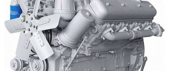
Diesel SMD-18N.01: in-line 4-cylinder with direct fuel injection
— 4-stroke — turbocharged — liquid-cooled — cylinder diameter 120 mm — piston stroke 140 mm — cylinder displacement 6.3 l — high-pressure fuel pump “Motorpal” (Czech Republic) PP4M10P1F-4214 — TU 4751-002-62638581 -2010
Catalog of parts and assembly units
Packing list Spare parts Microsoft Word document, 58 KB
Listen to the sound of the engine
Specifications
| Model | SMD-18N.01 |
| Rated power, kW (hp) | 73,6 (100) |
| Operating power, kW (hp) | 70 (95) |
| Rated rotation speed, rpm | 1800 |
| Minimum stable idle speed, no more than rpm | 600 |
| Maximum idle speed, no more than rpm | 1950 |
| Specific fuel consumption at rated power mode, no more than g/kWh (g/hp.h) | 224 (165) |
| Specific fuel consumption at operating power mode, no more than g/kWh (g/hp.h) | 231 (170) |
| Oil pressure in the main line of the diesel lubrication system at steady state operating mode and coolant temperature 80–95°C MPa (kgf/cm2): - at rated speed - at minimum stable idle speed, not less |
0,25–0,45 (2,5–4,5) 0,1 (1,0)
© 2010–2019, Belgorod Motor Plant CJSC
+7 (4722) 500-527
sales department phone number
Website development
Source
SMD-18: technical characteristics
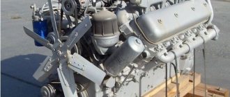
The old Soviet diesel engine SMD-18 is a four-stroke, four-cylinder in-line, liquid-cooled engine with direct fuel injection and, in the modification SMD-18N, turbocharged. This in-line “four” from Kharkov was created back in the 1950s, but remained in mass production until the second half of the 1990s, and in use until the 2010s. Because it is a simple, reliable, extremely durable and unpretentious engine.
Diesel engines SMD-18 and SMD-18N were used in agricultural tractors (for example, DT-75) and skidders (forestry, for example, TDT-55), combine harvesters (for example, SK-5 Niva) and excavators. In Soviet times, these engines were produced in huge quantities, so even despite the many years of absence of their manufacturer, problems with spare parts or repair stock do not arise.
SMD engine: characteristics, malfunctions and tuning. Engine ZIL-130 ICE ZIL-130
| Yumz with smd engine characteristics - BMW Master - Auto magazine Remove the hatch on the flywheel housing, located on the right side under the coarse fuel filter, and install an arrow under the bolt, aligning its end with the mark on the flywheel marked TDC. All modifications of T-150 tractors are equipped with diesel six-cylinder four-stroke supercharged SMD-60 engines with a 150-horsepower rated power. |
| Lubrication system of the SMD-18N diesel engine of the DT-75N tractor The price of the SMD-14 engine of the third configuration is 340,000 rubles, torque converter drive clutch, starting gearbox, PD10, starter, cooling system devices, generator. The number of crankshaft rotations reaches 2000 rpm, the nominal minimum value is 800 rpm, and the maximum nominal value is 2180 rpm. |
- SMD-15N.08 and SMD-15N.09 with a power of 68 hp. for the YuMZ tractor, Dnepropetrovsk;
- SMD-14N.02, SMD-14N.10; SMD-14N.16 for various road and construction equipment: asphalt pavers, road rollers and loaders;
SMD-18 • cooling, lubrication and exhaust systems;.
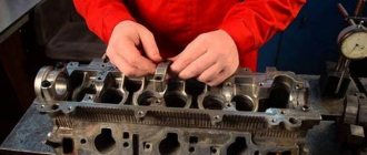
Crankcase and cylinder head
The crankcase is the most basic body part of the SMD-18 diesel engine. It houses parts of the crank and gas distribution mechanisms. The crankcase is a cast iron casting that forms the cylinder block, and the lower one forms the top of the crankshaft housing.
Cylinder liners are mounted in the vertical bores of the upper part of the crankcase. Coolant circulates in the cavity between the crankcase walls and the liners. Bores-beds are integrated into the transverse partitions of the lower part of the crankcase - the crankshaft main bearings are installed in them. The main bearing shells are made of steel-aluminum tape with an antifriction alloy.
On the side surfaces of the crankcase there are several machined mating surfaces for mounting components and assemblies of power, lubrication and cooling systems. The crankcase and cover 3 of the timing gear housing are attached to the front wall of the crankcase. A detachable front support is attached to the gear housing cover. The flywheel housing is attached to the rear wall of the crankcase. The flywheel housing has a special boss with a machined platform and flange for mounting the starting motor and gearbox.
Each cycle takes place during 2 revolutions of the crankshaft, including four strokes: intake, compression, power stroke and exhaust. The working stroke of the pistons in the cylinders follows the following cylinder operating order: 1-3-4-2.
Cylinder liners are “wet”, made of special cast iron. The sealing of the sleeves along the lower collar is made in the form of 2 rubber rings.
Engine Description
The line of six-cylinder V-shaped SMD engines is represented by engines such as SMD 60. 65 and their more powerful versions - SMD 72 and 73.
According to its design features, the SMD 60 is a four-stroke power device with direct injection of diesel fuel. The main component of this engine is the crankcase. In this type of engine, it is designed to combine the cylinders into one solid block and add to them the upper part of the crankshaft housing. The required rigidity in such an engine is achieved due to the presence of partitions between the cylinders and the end walls of the crankcase block.
This engine is cooled using water. In winter, it is possible to replace water with antifreeze in this system. The system has a centrifugal water pump, which ensures the necessary circulation of liquid throughout the closed cooling system.
crank mechanism
The crank mechanism converts the rectilinear reciprocating motion of the piston into the rotational motion of the crankshaft. The main parts of this mechanism are pistons with piston rings and pins, connecting rods, crankshaft and flywheel.
The pistons are made of aluminum alloy, equipped with three grooves for piston rings - 2 compression and 1 oil scraper.
The piston pins are hollow, made of chromium-nickel steel. Their outer surface is cemented and polished.
The connecting rods are stamped steel. The connecting rod rod is I-shaped in cross section. The upper head of the connecting rod has a bimetallic bushing. There are 3 holes in the upper head to lubricate the piston pin. The lower head of the connecting rod is detachable.
Connecting rod bearings are thin-walled, steel-aluminum, with an antifriction alloy. They are covered, for the best breaking-in, with a running-in layer. The upper and lower inserts are interchangeable.
The crankshaft is cast from cast iron, with increased counterweights, having 4 connecting rods and 5 main journals. Thin-walled liners with an antifriction alloy are used for main bearings.
At the rear end of the crankshaft, a flywheel is attached to the flange with 6 bolts. The flywheel ensures uniform rotation of the crankshaft, moving the pistons out of dead spots, and facilitates engine starting. To minimize vibrations, the crankshaft and flywheel must be balanced.
Gas distribution mechanism
The gas distribution mechanism ensures the intake of air into the cylinders and the removal of diesel combustion products from them. This mechanism is equipped with a suspended valve system consisting of: a camshaft, intake and exhaust valves, parts for their installation and drive: guide bushings, springs, plates with crackers, pushers, rods, struts, rocker arms, axles and adjusting screws with nuts.
The camshaft (three-bearing) is made of steel. Its support journals have different diameters. The largest diameter is at the front neck. The camshaft rotates from the crankshaft through timing gears located in a special crankcase at the front of the block.
Engine fuel system
The power system is designed to clean and supply atomized diesel fuel to the engine cylinders in quantities in accordance with its current operating mode.
It includes: a fuel pump with a regulator, a fuel priming pump with a manual priming pump, injectors, coarse and fine filters for diesel fuel, low and high pressure fuel lines, a diesel fuel tank.
Diesel fuel from the tank enters a coarse filter to remove large mechanical contaminants and water sediment. From the coarse filter, diesel fuel is sucked in by a booster pump and supplied under pressure to the fine filter. The purified diesel fuel goes to the fuel pump, which forces it through high-pressure pipes to the injectors.
When the diesel fuel pressure reaches the injector spring tension pressure, the injector nozzle needles are raised and diesel fuel is injected into the combustion chambers of the engine cylinders.
The fuel pump is a four-plunger pump, mounted on the engine on the left side with 4 bolts to the timing gear housing and at the bottom with 2 bolts to the special ones. bracket.
The fuel pump is equipped with an all-mode centrifugal-type regulator, which automatically, depending on the load, changes the power of the diesel engine, maintaining its operation in a stable and economical mode. The regulator also limits the maximum and maintains a minimum stable speed of rotation of the diesel crankshaft. The regulator is attached to the rear flange of the fuel pump housing.
Factors affecting tractor fuel consumption
Excessive fuel consumption (or less than expected fuel consumption) can be caused by several factors. For example, one of the main reasons is the technical condition of the tractor power unit. Experts advise checking the internal combustion engine for problems before starting work.
Photo source: exkavator.ru/trade Fuel consumption is determined by a number of different factors
The indicator is also affected by the operator's driving style (aggressive driving, incorrect speed or incorrect gear shift mode). Weather conditions, seasonality of work and landscape are also reasons for the increase or decrease in tractor fuel consumption.
The level of fuel consumption per hour when driving depends on the load capacity of the trailer, as well as on the type of road surface. Manufacturers distinguish three types of roads depending on their condition:
- Paved roads; field roads; packed snow roads.
- Roads with gravel, crushed stone (broken) or sandy (country) surfaces; unpaved roads after rain; turfed soil with hard surface; stubble of grain crops.
- Deep rutted roads; frozen or normal moisture arable land; ridge roads; thawed after a thaw; field after collecting root crops; virgin snow; off-road spring; broken roads.
Finding the necessary equipment or spare parts has become even easier - leave a request and they will call you back.
Turbocharger (modified SMD-18N)
For additional air injection into the cylinders, a turbocharger model TKR 8.5N-1 is installed on the SMD-18N diesel modification. It consists of a compressor (centrifugal single-stage) and a turbine (radial centripetal).
The body of this turbine is made of cast iron, equipped with a gas supply spiral channel (“scroll”) with a flange for attachment to the exhaust manifold. The compressor housing is cast from aluminum alloy, equipped with a central inlet pipe and a spiral channel with an outlet pipe. The compressor housing contains a diffuser disk.
Reviews of SMD-22 engines
The units and mechanisms on the engine are arranged taking into account the advantages of the V-shaped cylinder arrangement, which ensured the compactness of the engine installation on the T-150 tractor. To start the SMD-14 diesel engine, a single-cylinder starting carburetor two-stroke engine PD-10M2 or P-10UD with a power of 10 horsepower, with a starter and a single-stage gearbox is installed on the engine.
Lubrication system
The lubrication system includes: an oil pump with an oil receiver, a centrifuge, an oil radiator, oil channels, oil lines and a turbocharger oil filter. The gear oil pump, located in the front part of the crankcase, is driven by the crankshaft gear.
The lubrication system uninterruptedly supplies oil to the rubbing parts of a diesel engine, reducing their friction and wear, as well as removing heat and gradual wear products from them. The lubrication system is made according to a combined scheme: one part of the parts (main and connecting rod bearings of the crankshaft, camshaft bearings, valve mechanism, intermediate gear bushings and fuel pump gear) is lubricated under pressure, and the other (liners, pistons, rings, piston pins, camshaft cams) , pushers, gears) – by splashing.
During engine operation, oil is pumped from the lower crankcase by an oil pump through an oil receiver and supplied under pressure through an oil line and drillings in the crankcase to a full-flow centrifuge, and then to the oil cooler. The oil, purified in a centrifuge and cooled in an oil cooler, goes into the main oil line, which runs along the block.
From it, oil is supplied through inclined channels in the crankcase to the crankshaft main bearings, lubricating them, and then through drillings in the crankshaft journals and cheeks to the connecting rod bearings, etc.
To clean the oil, the engine has an oil filter - a full-flow oil centrifuge.
Diesel cooling system SMD-18
The cooling system removes heat from the hottest engine parts (liner, cylinder block, cylinder head) and maintains the necessary thermal regulation of the diesel engine.
Both antifreeze and ordinary water are used as a coolant.
The cooling system of the SMD-18 diesel engine is a closed forced one; fluid is circulated through it using a centrifugal water pump.
The cooling system consists of a radiator, a water pump with a fan, water cavities in the block and cylinder head connected to the starting engine cooling system.
To automatically regulate the temperature regime, a thermostat model TS-107 is installed on the diesel engine. The thermostat is located in an aluminum housing mounted on a water pipe and is connected to the upper radiator reservoir and water pump with hoses.
It is a one-piece structure, which consists of a brass body, a stand, and a holder, fastened together. This is how the thermostat works. When the coolant temperature rises above +80°C, the filler, heating up, expands in volume and puts pressure on the rubber insert 10, which in turn contracts and tends to push out the piston. As the coolant temperature continues to rise, the valve opens fully and flow passes through the radiator.
The coolant is poured through the radiator neck and fills the entire cooling system of the diesel engine and the starting motor.
When a diesel engine is running, coolant from the lower radiator tank goes through a pipe to the water pump, and it pumps it into the water distribution channel of the crankcase. From the water distribution channel, the coolant enters through the windows into the space between the walls of the block and the liners (water jacket), and, washing the liners, cools them.
From the crankcase, through the water supply channels, it rises into the water jacket of the cylinder head, from there, through the drainage pipe through the thermostat (if the valve is open), it enters the upper radiator tank. Flowing through the tubes of the radiator core, the liquid is cooled by the air flow, which is pumped by the fan.
The water pump is combined with the fan using a common drive and is located at the front end of the cylinder block.
Oil pressure in the main line of the diesel lubrication system at steady state
In addition, these engines also feature oil cooling of the pistons, damping of torsional vibrations, and improved temperature conditions of the diesel engine by introducing an oil-water heat exchanger. Developed for specific operating conditions, they are, as a rule, perfectly balanced and interference with their design does not lead to positive results.
SMD-18 diesel starting device
For easy starting of the diesel engine there is a starting device, which consists of a starting motor model P-10UD and a gearbox model RPD1.000M.
Starting motor P-10UD – 1-cylinder, carburetor, two-stroke, with crank-gum purge. Its operating power is 10 horsepower (7.36 kW), with a crankshaft speed of 58.3 rpm (3500 rpm). The motor is attached to the flange of the engine flywheel housing. It is started by the ST Z62 starter.
The starting engine consists of the following parts: crankcase, cylinder, crank mechanism, carburetor, ignition system and regulator. Since the crankshaft speed of the starting motor increases rapidly under light loads or at idle, this can lead to motor failure. Therefore, to limit the highest crankshaft speed, the engine has a single-mode centrifugal ball regulator. As the regulator shaft rotates, the balls, under the influence of the resulting centrifugal force, try to move apart in the grooves of the drive disk and move the movable disk 10 away. The movable disk is kept from moving by a special spring.
When the crankshaft rotation speed changes, the centrifugal force of the balls changes, as a result of which they diverge or converge, act on the movable disk and turn the levers - internal and external. A lever connected to the carburetor throttle lever closes or opens the throttle when turned, thereby limiting the maximum engine speed.
The starting engine ignition system includes an M124-B1 magneto, high voltage wires and spark plugs. A magneto is used to generate high-voltage electric current pulses and supply it to the spark plug at a strictly defined moment.
Engine description... SMD-31 engines
| SMD engines: technical characteristics, design, reviews When rotating the crankshaft with the cylinder head caps removed, it is necessary to monitor the movement of the valves of the first cylinder; after the exhaust valve and then the intake valve open, press the TDC indicator located on the right side of the flywheel housing and continue to rotate the crankshaft until the indicator rod falls into the hole on the flywheel. Despite the fact that mass production of this kind of motors has been completely discontinued, thanks to their excellent performance indicators they remain relevant and are able to compete with many modern analogues. |
Diesel hydraulic pumps SMD-18
To ensure the operation of hydraulic mechanisms that are used on the tractor or together with it, this diesel engine is equipped with two gear pumps: NSh5O-2-L (left rotation), which is used in the tractor’s hydraulic lifting system, and NSh1OE-3-L left rotation, which used in the hydraulic servo system to supply oil to the hydraulic booster for controlling the main clutch.
The hydraulic pump is attached to a drive mounted on the gear housing and is driven by a gear that is in constant mesh with the camshaft gear. The transmission of rotation to the hydraulic pump is carried out by a cam coupling, the fixed half of which is made integral with the drive shaft, and the other moves freely along the splined shaft of the pump drive gear.
When the gears rotate, the disengaged teeth create a vacuum, and oil is sucked from the reservoir into the pump housing. When filling the cavities between the teeth, the liquid is pumped into the discharge cavity. When engaged, the gear teeth force the oil into the discharge pipeline.
To reduce internal oil flows through the gaps between the end surfaces of the gears and bushings, the pump is equipped with automatic control of the size of the gaps at the ends of the gears. Oil from the pressure chamber enters the cavity above the bushings and tends to press bushings 13 and 15 towards the ends of the gears, while at the same time, oil also presses on the bushings from the side of the gears, but over a slightly smaller area, resulting in the force pressing the bushings to the ends of the gears. is small, and the bushings wear out slightly.