- home
- Media center
- Articles
- Replacing the clutch on the T 25 tractor
Menu
- News
- Articles
- Video materials
- Photo materials
- Publication in the media
- 3D tour
20.07.2020
The T 25 tractor is equipped with a dry format single-disc clutch. The operating principle of the latter is based on the functioning of several structural elements: driven and driven disks, friction linings, springs and a cast iron flywheel. Through the transfer of energy between them, friction occurs, which transfers energy to the entire system.
Structural differences
The T-25 tractor clutch has distinctive features in comparison with identical types of equipment. The power flow extends in the direction from the casing and flywheel to the drive gears. This ensures a constant supply of power from the operating motor to the hydraulic pump. The clutch itself is contained inside a housing that is connected to the crankcase.
The clutch of the T-25 tractor consists of three interacting parts: a pressure plate, a flywheel and a casing. The latter two are fastened using several bolts and centering pins. Rotation is realized through guides. They are pressed and subsequently tightened with a washer. The pressure plate moves freely. Due to this, the driven disk is pressed towards the flywheel.
Adjustment work
Correct adjustment of the tractor clutch is characterized by the presence of a gap between the bearing system and the release lever cams. It should be no more than 2-3 millimeters. When worn, the original properties are lost, which leads to weakening of the linings.
This also leads to other problems, which include slipping of the clutch when disengaged. If the gap exceeds the standard, it will be difficult to turn on the machine.
The connecting housing is equipped with a cover, when opening which you can perform the required diagnostic and adjustment work. The gap is changed by adjusting the screws connecting the bearing and the arms of the levers.
The clutch is adjusted by performing the following list of actions:
Description
During operation of the tractor, almost all of its components are subject to wear and tear.
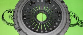
The clutch basket (clutch) also needs repair.
Its defects can be the following: cracks, wear, thread failure, broken tab, failure of the release bearing.
Unevenness of the driven disks can be eliminated by editing on the reference plate, or replaced
If the driven disc linings have become unusable and/or their thickness has reached the limit, they must be replaced.
If the working surfaces are worn or scuffed, the drive disks can be ground and/or ground if possible until signs of wear are eliminated
The clutch shaft also has its own adjustments.
If the surface of the bearing shaft is worn, replace the worn part
If the release lever cams are worn out, the levers naturally need to be replaced.
If the hole in the release lever under the finger and the surface of the bearing housing under the release clutch housing and under the bearing wear out, then the levers naturally need to be replaced.
If the part cannot be repaired, then new spare parts for repairing the tractor clutch basket, and others, can be purchased in the AGROTECHCENTER online store.
Additional Tips
The T25 tractor must be operated according to the instructions supplied with the machine. With the onset of the cold season, operating conditions become more difficult. Therefore, to ensure proper operation of special equipment, it is recommended to take into account the following tips:
To avoid negative consequences during self-repair, replacing the clutch on a T25 model tractor must be carried out in accordance with the rules described in the technical documentation or manual. Also, periodic contact with specialists for the purpose of a full technical inspection and diagnostic work is a mandatory procedure.
Source
Search
Clutch of the T-25 tractor, its diagram and regulation Today’s article will discuss one of the important points of working with the T-25 tractor. diagram and principle of operation of the clutch. Clutch basket design, these valuable tips for maintaining its integrity and extending its life, and making modifications will also be discussed.
What is Delight Tractor T-25 and the basics of its operation
The clutch is a complete assembly (the pedal pushes another handle, the basket, in other words, the clutch) that temporarily disconnects the gearbox (transmission) from the engine when changing gears and additionally rotates them when the tractor is started.
The T-25 tractor clutch consists of a dry single-disc continuous-action clutch. a disk is secured using springs
with special linings consisting of a material with a high coefficient of friction (friction).
Under the influence of springs in the middle of these surfaces and the drive disk, a friction force arises, which transmits engine torque to the driven clutch shaft, and then to the main transmission of the T-25 tractor. When the clutch disengages, the spring force on the main disc stops.
Important! The main feature of the T-25 clutch is the presence of a second power supply. Transition from the engine through the flywheel and clutch basket to the gears of the hydraulic pump drive.
Clutch disc t 25 which side.
It turns out that the transmission passes through some friction surfaces of the clutch. For this reason, power is constantly transferred from the running engine to the pump.
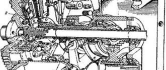
Clutch diagram Tractor T-25
Below we present a detailed diagram of the clutch basket and describe the main points that arise during its operation.
You may also like
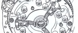
The bushing is located inside the cast iron body (8). The housing itself is bolted to the engine flywheel housing (7) and aligned with the collar. The leading elements of the basket are the flywheel itself (1), the casing together with the hub (5) and the pressure plate (5). The housing is attached to the flywheel with two pins and 6 bolts. Rotation from the flywheel to the disk is transmitted through the housing by guide pins (22).
The springs are located in the recesses of the disk and are supported there by thermal insulation, which also protects the springs from possible overheating when the tractor slides.
This video explains and shows how to install the clutch disc
Suitable for almost any car.
To be able, heat was better removed from the sources. clutch and pressure cooker. The glasses are made with a special cross-section.
Which side should I put the ZIL 130 clutch disc on?
In the center (5) there are three smooth holes in the disk itself. three threaded holes for bolts that connect the disk
with springs and the casing itself.
Drive steel disc (3). moves freely along the grooves of the basket shaft (4), and together with it the hub and two asbestos gaskets have free movement.
A double row ball bearing located in the crankshaft bore serves as the front support for the pushrod.
In the area of the central hole of the connecting body there are points: internal (18) and external (28), which form a cavity. The drive mechanism (16) leads to the hydraulic pump.
What is the T-25 tractor clutch and the basics of its operation
A clutch is a mechanism assembly (release pedal or handle, basket or clutch), which serves to temporarily disconnect the power transmission (transmission) from the engine when changing speed gears, as well as engage them when starting the tractor.
The T-25 tractor clutch consists of a dry single-disc permanently closed clutch. Its principle of operation is based on the fact that in the middle of two cast-iron surfaces of the flywheel and pressure plate, a drive disk with special linings consisting of a material with a high coefficient of friction (friction) is attached using springs.
Under the influence of springs, a friction force arises in the middle of these surfaces and the drive disk, which ensures the transmission of engine torque to the driven shaft of the clutch and then to the main gear of the T-25 tractor. When the clutch is disengaged, the spring force on the main disk stops.
Important! The main feature of the T-25 tractor clutch is the presence of a second power flow. Which goes from the engine through the flywheel and clutch basket housing to the gear wheels of the hydraulic pump drive.
In this case, it turns out that the transmission bypasses some friction surfaces of the clutch. Because of this, power is constantly transferred from the running engine to the pump.
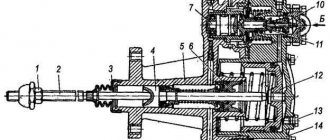
T-25 tractor clutch diagram
Below we will provide a detailed diagram of the clutch basket and describe the main points that arise during its operation.
The coupling is located inside the cast iron housing (8). The housing itself is bolted to the engine flywheel housing (7) and is aligned along the collar. The leading elements of the basket are the flywheel itself (1), the skin together with the hub (5) and the pressure plate (2). The housing is attached to the flywheel using two pins and 6 bolts. Rotation from the flywheel to the disk is transmitted through the casing using guide pins (22).
The springs are located in the recesses of the disk and rest on it with the help of thermal insulating gaskets, which also protect the springs from possible overheating when the tractor slips.
In order to better dissipate heat from the clutch springs and pressure plate, the cups are made with special transverse ones.
In the central part (5) there are three smooth holes, and in the disk itself there are three threaded holes for bolts that connect the disk with the springs and the casing itself.
The driven steel disk (3) moves freely along the splines of the basket shaft (4), and the hub and two asbestos linings also have free movement.
A double-row ball bearing located in the crankshaft bore serves as a front support for the driven one.
In the area of the central bore of the connecting body there are cups: internal (18) and external (28), which form a cavity. It contains a gear wheel (16) of the drive leading to the hydraulic pump.
The gear, which is pressed onto the hub (20), is fixed to it using a parallel key. The rotation of the gear is carried out using two bearings (17).
The inner splined part of the hub (20) rests on special splines of the hollow shaft (15). It transmits rotation from the clutch housing to the drive gear. The driven gear (27) is in constant engagement with the drive gear (16) of the hydraulic pump drive, and is located in the housing (25). For this purpose, special hatches are made that connect the gears in the inner cup and the housing.
Oil is poured into the pump drive and drive gear through hole (25), which is closed with a plug having a conical thread. In the upper part of the connecting casing, on top of the main gear cavity, there is a breather that prevents the internal pressure of the system from increasing.
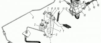
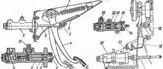
Clutch pedal diagram and operating principle
The clutch pedal is mounted on a shaft (9), it passes through the bores of the main gear (6). Its second end is connected using a fork (7) and a rod (8) to the gear lock lever (5). The pedal is connected to the roller that disengages the clutch using a rod (10).
The diagram shows with a dotted line the moment when the clutch pedal is fully depressed, then the pin (2) should rest against the floor (4). This leads to the fact that the clutch is completely disengaged, and the lever (5) moves the roller to the forward position, thereby freely changing the tractor gears.
If the pedal is lowered, then the pin (3) rests on the floor (4), then the clutch is engaged and shifting is impossible.
Clutch adjustment
With use, the driven disc linings are subject to friction and wear out. As a result, the gap between the ends of the release levers (paws) and the thrust bearing is reduced. Timely adjustment of the T 40 clutch feet restores the clearance and reduces friction.
The normal gap should be 4 mm. As this indicator decreases, the ends of the levers will begin to come into contact with the bearing, the clutch will begin to slip, which in turn will lead to increased friction and both parts will wear out faster.
The question of how to adjust the clutch on the T 40 tractor arises after the pedal stroke decreases to 2.5 cm. There is no need to measure millimeters before adjusting and wait for the exact value: when the pedal stroke decreases, it becomes more difficult to squeeze the clutch, it is “tight.” Adjustment can be done in two ways: using rods or bolts. Before you start working, you should watch a couple of videos to answer any possible questions.
T-40 clutch diagram
Traction adjustment
Procedure:
Be sure to read: Final drive design
Adjustment by changing the length of the rod is quite simple, accessible to a novice mechanic and does not take much time. However, in some cases this method is not suitable. In this case, adjustment is used using adjusting bolts.
Bolt adjustment
Procedure:
When repairing the clutch basket, it is important to correctly install the servo springs - this is a special mechanism that makes it easier to depress the pedal. The springs are installed exactly in the hole of the bracket, after first moving the pedal to the upper position.
Parts and adjustments of the clutch of the MTZ-1221 tractor
Insufficient force of the pressure springs; shrinkage of the springs due to prolonged slipping and overheating of the coupling - Replace the pressure springs. Using a short-handled screwdriver, turn the screw until the lever begins to press the feeler gauge against the release bearing. Replacing the MTZ 82 clutch Correct adjustment of the clutch of the MTZ 82 80 tractor is done in two stages: Installation of the release levers-claws relative to the basket hub Adjustment of the free travel of the clutch control pedal Adjustment of the position of the release levers-claws of the MTZ 80 82 clutch Adjustment is carried out during assembly with the basket installed on engine and disconnected transmission housing.
MTZ tractor reviews. Replacing the MTZ 82 clutch Correct adjustment of the clutch of the MTZ 82 80 tractor is done in two stages: Installation of the release levers-claws relative to the basket hub Adjustment of the free travel of the clutch control pedal Adjustment of the position of the release levers-claws of the MTZ 80 82 clutch Adjustment is carried out during assembly with the basket installed on engine and disconnected transmission housing.
At the very end of the contract, the finger is secured. The main parts of the clutch are:. Check the pedal travel by measuring it against the thrust pad. Then an initial inspection of the unit is performed. The adjustment involves first installing a splined mandrel into the flywheel bearing.
MTZ clutch control
The clutch is released by pedal 14 acting on rod 19 and piston 20 of the master cylinder. The clutch on the MTZ 1221 is stuck
We recommend: repair of MTZ-80 gearbox
Which side should the clutch disc be placed towards the engine? Which is correct?
Which side should the clutch disc be placed towards the engine? Which is correct?
I have my own sad experience of incorrectly installing the flywheel disc, when I assembled everything and at the first start there was no clutch at all, and even grinding sounds were heard. I had to remove the box again and change the disk side. Technically, this is what happened:
The disc hub rested against the flywheel support bearing, and the damper springs rested against the flywheel mounting bolts. Because of this, a gap of several millimeters has formed between the disc and the flywheel (that’s right - the working part of the clutch disc should fit snugly against the working surface of the flywheel)
The basket pressed on the disk from the reverse side, which led to the disk being pinched between the basket and the flywheel. Even when the clutch was depressed, the release bearing did not do its job, and the clutch disc remained clamped, but torque was transmitted from the engine through the clamped hub and the damper spring housing.
MTZ 82
A malfunction of the clutch of the Belarus tractor is indicated by various problems in the operation of the machine:
- Insufficient torque transmitted by the clutch. The reason is wear or complete failure of the driven disc lining. If the adjustment does not help, replace this clutch assembly.
- Incomplete disengagement of the clutch, in which the free play of the pedal is greater than normal. The problem is solved by adjusting the clutch.
- Oil leaking into the dry compartment of the basket. The reason is failure of the crankshaft seal, cuff of the lift bracket, or extrusion of the bearing cover of the driven shaft of the PTO drive. The solution to the problem is partial replacement of the tractor clutch elements.
When carrying out regular maintenance, be sure to inspect all components of the machine, because if the drive is incorrectly adjusted and the gaps between the levers are reduced, the bearing overheats and lubricant leaks. As a result, the assembly completely jams, and the contacts of the levers burn out.
When replacing the clutch of the MTZ 82 Belarus tractor, technological bolts are screwed into the flywheel to compress the pressure springs and first unscrew the support disk fastenings, and then the technological ones. Before disassembly, marks are applied to the casing and disks so that during assembly the parts can be placed correctly and their balance maintained.
If the thickness of the driven disk is insufficient, the friction linings or the assembly are replaced. After this procedure, the sinking of the rivet heads should be more than 2 mm. Be sure to check the tightness of the pads; the minimum value is 0.1 mm. If, with normal disk thickness, the rivets are recessed by 0.1 mm, then both friction linings are replaced.
To directly replace the clutch, compress the pressure plate springs and screw in the technological bolts, fixing the position. A process shaft is placed inside the flywheel bearing race to correct the installation of the spitz hubs and align the flywheel axis.
How to install a clutch disc: step-by-step instructions
The clutch performs the most important function - it ensures smooth gear shifting, so that the car starts smoothly, the transmission and engine function correctly and do not fail ahead of time.
Due to the fact that the clutch experiences increased loads, it has to be changed quite often, every 100,000 kilometers. How do you know when it's time to install a new clutch disc?
The following signs indicate that this element has become unusable: slippage appears, the clutch does not disengage completely, gears are difficult to shift, the clutch pedal becomes too tight or falls, and the car loses traction.
Not every car owner is well versed in how to properly replace this element. What happens if you install the clutch disc incorrectly? The result of such a repair will be the following: you will have to disassemble the unit again, because the disk will not be able to function properly and will begin to malfunction.
Most often, a new clutch basket is also installed, but there are situations when you can get by with replacing one disc. Although this is generally not a very complicated procedure, many car owners do not know how to properly install the clutch disc. There are 2 methods for performing this operation:
Of course, the second method is much simpler. By the way, if the car is rear-wheel drive, then even a beginner can handle this job. Installing the clutch if the car has front-wheel drive will not be easy, but if you apply the right amount of effort, you can do it yourself. Let's figure out how to install the clutch correctly step by step.
To install the clutch yourself, the car is driven onto an overpass or a hole in the garage. Before you begin dismantling, you should place a special stop under each wheel to prevent the car from rolling away.
Which side to install the clutch disc t 25
TRACTOR CLUTCH T-25
The T-25 tractor is equipped with a dry single-disc permanently closed clutch.
The principle of operation of the clutch is based on the fact that between two dry cast-iron surfaces of the flywheel and the pressure plate, a driven disk with linings made of friction material with a high coefficient of friction is clamped by springs. Under the action of springs, friction forces arise between the driving surfaces and the driven disk, which ensure the transmission of torque from the engine to the driven disk and the driven shaft of the clutch and further to the tractor's main gear. When the clutch is disengaged, the driven disk is released from the forces of the springs and the transmission of rotation from the engine to the main gear stops.
Replacing the clutch on the T 25 tractor
The T 25 tractor is equipped with a dry format single-disc clutch. The operating principle of the latter is based on the functioning of several structural elements: driven and driven disks, friction linings, springs and a cast iron flywheel. Through the transfer of energy between them, friction occurs, which transfers energy to the entire system.
Clutch operating principle
The clutch is used when the engine crankshaft is disconnected from the gearbox. It is also necessary to ensure their smooth connection, for example when you change gear while driving off.
Both trucks and passenger cars are most often equipped with a single-plate friction type clutch. The Citroen C4 sedan clutch combines a release mechanism and actuator. The mechanism is located on the engine flywheel, while the drive is located on parts that do not rotate: on the frame, the car body.
The main components of the clutch on a Citroen C4 sedan are a driven disk placed on the splines of the gearbox drive shaft, a pressure disk with springs mounted on the clutch housing, which in turn is firmly fixed to the flywheel. The release levers, connected by hinges to the pressure plate, are also located on the casing using ball joints.
The clutch release drive for the Citroen C4 sedan includes a clutch with a release bearing, a return spring, as well as a fork, rod and pedal.
When you release the pedal, the driven disc is pressed by springs between the flywheel and the pressure plate. At this moment, the clutch is considered to be engaged, since during engine operation torque is transmitted from the flywheel and pressure plate to the driven disc (due to friction force). The torque is then transmitted to the transmission drive shaft. When you press the clutch pedal, the rod will move and the fork will rotate around the place where it is attached.
The clutch is under pressure from the free end of the fork, so it moves towards the flywheel. Also, the free end of the fork presses on the levers, which in turn move the pressure plate. At this moment, the driven disk is no longer under the influence of compressive force, it moves away from the flywheel - therefore, the clutch is disengaged.
Recommended articles to read:
Maintenance and basic gearbox adjustments
8.1. Starting and stopping the engineThe diesel engines of the tractors in question are started either directly with an electric starter or using an additional gasoline engine. The sequence of operator actions when starting directly with an electric starter is as follows: after making sure that the gear shift levers, the hydraulic linkage system and the power take-off shaft are in the neutral position, turn on the “ground” of the battery and the decompressor; move the fuel supply control lever to the “off” position; disengage the clutch and hold it in this position until the diesel engine is started; turn on the starter.
After 3-5 seconds. after the start of stable rotation of the diesel crankshaft, turn off the decompressor and turn on the fuel supply. As soon as the diesel engine starts working, turn off the starter and engage (slowly) the clutch.
If diesel for 10 sec. after turning off the decompressor did not start, turn off the starter and, after about a 30 second break, repeat the start. If after 2-3 attempts the diesel engine does not start, it is necessary to find and eliminate the cause of the malfunction.
In cold weather, the glow plugs are turned on before turning on the starter. (turn the starter key until the first lock).
To preserve the capacity of the batteries, it is recommended to turn off the glow plug in the summer by removing the wire from it and insulating the tip.
The clutch is disengaged to facilitate cranking. When the engine and transmission are warmed up or the engine is started in warm weather, the clutch may not be disengaged and the decompressor may not be turned on.
<>After starting, the diesel engine is warmed up at an average crankshaft speed.
The diesel engine is started in a cascade manner in the following sequence:
- open the fuel tank tap of the starting engine and turn on the “ground”; cover the carburetor air damper and turn on the starter at 2 - 3 with the ignition off (holding the button pressed) - to lubricate the crank mechanism of the starting engine; turn on the ignition (by removing your hand from the shutdown button) and open the carburetor choke (by moving the control lever away from you), after which the starting engine should start (the starter button is released). The duration of continuous operation of the electric starter at start-up should not exceed 15 s. If the engine does not start, make the next attempt after about a minute. After 3 - 4 unsuccessful attempts to start the starting engine, you need to start troubleshooting; Warm up the engine for 2 - 3 minutes. with minimum and nominal crankshaft rotation speeds (by adjusting the position of the air damper using a rod); after warming up, the starting engine is stopped, the drive gear of the gearbox is engaged with the crown of the diesel flywheel (by pressing the power pedal with your foot); disengage the gearbox clutch; turn on the diesel decompressor and move the fuel supply control lever to the “off” position; start the starting engine and, having established the full speed of the crankshaft, smoothly engage the clutch; by turning the diesel crankshaft for 3 - 4 s. turn off the decompressor and turn on the fuel supply to the cylinders. After starting the diesel engine, remove your foot from the starter gear pedal (the engines - starting and diesel - are separated) and stop the starting engine by pressing the ignition switch off button. Close the fuel tank tap of the starting engine.
Continuous operation of the starting motor at full power should not be long (up to 15 minutes) to avoid overheating.
If necessary, the starting motor can be started manually using a special device (available in the spare parts kit).
A heated diesel engine starts without turning on the decompressor. While the diesel engine is warming up, the hydraulic pump is turned on. Load the diesel engine after it has been warmed up to at least 40°C.
To facilitate starting a diesel engine in the winter season by injecting a flammable liquid into the intake manifold, a 5-PP-40A starting device is designed, which is used as follows:
- de-energize the starting glow plug, for which they remove the wire going to it from the additional resistance terminal and insulate it with insulating tape; perform standard operations of preparing the tractor diesel engine for start-up, while the clutch is disengaged and the fuel supply control lever is set to the maximum supply position. open the mixer lid (see Fig. 32), install a capsule with starting fluid and screw the lid tightly onto the mixer; by pressing the needle handle (all the way), they pierce the capsule and perform 2-3 double strokes with the pump handle to fill the system with starting fluid. simultaneously with turning on the starter, make 30-60 double pumps per minute (depending on the ambient temperature) to supply starting fluid. As soon as the diesel engine starts, turn off the starter, continuing to supply fluid until the diesel engine operates stable.
If all requirements are correctly met, reliable diesel starting is ensured, with the device, at temperatures down to minus 25°C.
Stopping the engine. To stop the engine, smoothly reduce the crankshaft speed to medium, and after a few minutes to minimum; turn off the fuel supply to the cylinders (by moving the fuel pump control lever and regulator); turn off the “mass”. You cannot stop the engine: by closing the fuel tank supply valve; turning on the decompression mechanism.
For an emergency (emergency) engine stop, the fuel supply to the cylinders is stopped and the decompression mechanism is turned on.
8.2. Start of movement
To start the tractor, you must:
- reduce the rotation speed of the diesel engine; disengage the clutch (quickly and fully pressing the pedal with the middle of the sole); holding the clutch in the disengaged state for several seconds, engage the desired gear (if the engagement of the gears did not take place due to tooth abutting tooth, repeat the steps, starting with disengaging the clutch); use the lever or pedal to control the fuel pump and regulator to increase the rotation speed of the diesel crankshaft; smoothly, without delays in intermediate positions, reduce the force of your foot on the clutch pedal, turning it on (continuing, if necessary, increasing the rotation speed of the diesel crankshaft so that it does not stop when the traction load is connected).
Engaging the clutch too quickly can cause the engine to stall.
When starting the tractor on an uphill slope, you must:
- press the pedal or button of the parking brake lever (releasing its lock); disengage the clutch; After a few seconds, engage one of the lower gears (the gear number depends on the steepness of the surface); increase the engine speed; simultaneously with releasing the tractor brake, engage the clutch (preventing the tractor from rolling back).
Starting the tractor on a descent is possible in all gears, provided that the selected gear, if necessary, provides engine braking.
8.3. Changing the driving speed
Depending on the technology of the work being performed, the terrain, the state of the supporting surface, etc., it becomes necessary to change the speed of movement of the unit (at the same time, the traction force of the tractor also changes). This is achieved by: increasing or decreasing the fuel supply to the engine cylinders (by changing the engine speed), by changing gears (by changing the transmission ratio).
In cases where it is necessary to change the speed (traction force) within a larger range than a change in the crankshaft rotation speed allows, use gear shifting. Sequence of operator actions: the clutch is disengaged, the gear is changed (by moving the gear lever to a different position), the clutch is engaged (smoothly). The engine load and the need to change gears are determined in this way: if, after switching to a higher gear, black smoke comes out of the engine exhaust pipe (not immediately), this indicates that it is overloaded (you need to switch to a lower gear).
It is prohibited to use slow gears to increase traction forces, since they are not designed to work under heavy loads (only to reduce the speed of movement, that is, technological).
8.4. Changing the direction of travel
Smooth turning of the tractor occurs due to smooth rotation of the steering wheel (with both hands) in the desired direction. You cannot rotate the steering wheel: by moving your hands on one side; one hand; for the knitting needles; with crossed arms; with both hands at the top of the steering wheel. A sharp turn of the tractors in question is carried out using (additionally) braking of the drive wheel of the side in which the turn is being made (this is especially effective on a slippery road).
8.5. Overcoming obstacles such as ditch and logs
When approaching an obstacle, evaluate the conditions for overcoming it (this may require stopping the tractor). Most obstacles are overcome at right angles, which improves wheel traction and reduces the likelihood of the tractor skidding and overturning. Movement is carried out in low gears; in case of wheel slipping, use a differential lock.
- To overcome a ditch with a tractor, the following sequence of operator actions is recommended: when approaching an obstacle, engage one of the lower gears; at the moment when the front part of the tractor begins to lower, reduce the engine crankshaft speed; from the moment the wheels reach the bottom of the ditch, increase the fuel supply (preparing the engine to overcome increasing resistance); driving to the opposite wall of the ditch must be accompanied by an increase in fuel supply to the engine cylinders; repeat these steps from the moment the rear wheels of the tractor approach the ditch. In cases where the ditch has steep walls and the depth reaches (or is greater than) the radius of the smaller tractor wheels, a deck is needed to overcome the obstacle. When overcoming an obstacle such as a log, you must perform the following actions: approach the obstacle in one of the lower gears until the front wheels stop against the log; increase the fuel supply and run over a log; when the wheels are at the top, immediately reduce the fuel supply and, if necessary, descend; When approaching an obstacle with the rear wheels, repeat the steps.
8.6. Reversing
Reverse movement (short-term) is used to drive up to implements and machines, turn them around, and move tractors for loading (unloading) or to a parking (storage) place.
If the tractor has several reverse gears, the operator uses the one that will ensure the accuracy and safety of movement required for this operation.
Reverse gear is engaged only after the tractor has come to a complete stop; the sequence of actions is similar to engaging forward gears.
It is recommended to observe movement and stopping through the left shoulder (less physical strain will be required). You need to use your hearing to control the operation of the engine, because untimely (erroneous) actions with the clutch or brake pedals can cause it to stop.
For long-term operation in reverse gears, the T-25A tractors provide rearrangement of the steering and seat. In this case, the wheels are swapped so that the arrows on the tires correspond to the main direction of movement.
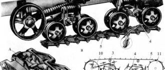
To improve the traction and grip properties of tractors, the following is provided: regulation of air pressure in tires, keeping in mind that an increase in pressure reduces the traction properties of the engine, and lower than permissible pressure causes accelerated wear; use of all wheels in driving mode (T-40AM, T-40ANM); blocking the differential of the drive axle (turned on after disengaging the clutch, movement is only possible in a straight line, for a short time); increasing the traction force of gravity (special weights on the drive wheel disks and the front axle beam, a mechanical additional loader combined with the tractor’s linkage mechanism); filling the chambers of the drive wheels with liquid. Chains can also be used to wrap around the tires and secure them with clamps. To prevent the chains from sagging and damaging the tires, reduce the air pressure before putting it on, and after fastening it, bring it to normal.
8.7. Features of control of tractor transport units
When preparing a tractor for work as part of a vehicle, the main attention is required: the brake system, steering, and coupling device. Semi-trailers are connected to the tractor only using a hydraulic hook.
When the transport unit turns, the trailer moves towards the center of the turn, that is, it moves along a curve of a smaller radius than the tractor. Therefore, to drive through a narrow area with a turn, for example to the left, the tractor must be driven to the right edge.
Working braking of the tractor movement can be performed: 1 - brakes with the engine turned off; 2 — by the engine, reducing the crankshaft speed without disengaging the clutch; 3 - combined.
According to the first method, the operator’s actions are as follows:
- reduce the fuel supply to the engine cylinders and simultaneously disengage the clutch; smoothly press the interlocked brake pedals, reducing the speed to the required speed or until the tractor (unit) comes to a complete stop.
The second method is most effective when driving on a slippery road, on slopes. Due to the fact that engine braking is not sharp and the braking force is transmitted evenly to the left and right wheels, skidding is prevented in this way.
The third method is used in cases where it is impossible to obtain the required braking force to quickly reduce the speed of the tractor (or stop it) using engine braking (especially on steep slopes). The operator's actions in this case are as follows:
- reduce the fuel supply to the engine cylinders; Without disengaging the clutch, smoothly press the interlocked brake pedals. In this case, you need to carefully monitor the engine crankshaft speed: when it drops to a minimum, disengage the clutch (so that the engine does not stop); while holding the clutch and brake pedals, switch off the gear; release the clutch and brake pedals. This method is also used for emergency shutdown of the unit.
Driving on mountain roads. Approaching a rise, they evaluate its steepness and length, the power of the tractor engine, and the traction of the wheels with the road surface in order to select a gear in which it will be possible to overcome the entire rise without stopping.
When descending, select a gear in which it would be possible to move in the opposite direction (uphill). Driving on a descent with the gear turned off is prohibited (due to the impossibility of keeping the unit from accelerating and loss of controllability). To reliably hold the unit on an ascent or descent, in addition to the parking brake, one of the lower gears is engaged (on an ascent in forward gear, on a descent in reverse).
Special traffic conditions. When crossing the river along the bottom, you need to move evenly, straight, without stopping, in one of the lower gears. When crossing on ice (if its thickness exceeds 0.1 m), both cabin doors must be open, there is one person (operator) in the cabin, the speed is constant. In off-road conditions, movement should be at a speed lower than in normal conditions, without sudden changes in speed and direction of movement, braking is performed by the engine or a combined method, coasting cannot be used. It is prohibited to drive the transport unit at night if the lighting (alarm) is faulty.
Towing. Towing of tractors (as an exception) is carried out using a flexible (cable 4-6 m long) or rigid (metal rod with a diameter of 75-100 mm, length 1.5-4 m) hitch.
The power and weight of the towing vehicle must be greater than or equal to that of the towed vehicle.
A flexible hitch can be used to tow a tractor with working brakes, steering, and lighting. In mountainous areas, towing with a flexible hitch is prohibited.
If the tractor's brake system is faulty, it is towed on a rigid hitch (the steering and alarm systems must be in working order).
Recommendations for use
The following recommendations must be followed:
Be sure to read: Technical characteristics of the D-160 engine
If you follow these simple rules, the mechanism will work correctly and without breakdowns for a long time.
The clutch basket is a fairly simple and reliable mechanism, but requires periodic maintenance. It comes down to lubricating rubbing parts, checking threaded connections and tightening them, if necessary. For lubrication, solid oil and a rod syringe are used, with which the lubricant is introduced through a grease fitting located on the same side as the basket. This way, the lubricant will get onto the rubbing surfaces of the bracket and the offset, as well as into the offset bearing of the main clutch. The couplings themselves are not lubricated, as they are made of the dry type. The procedure is carried out every 240 operating hours of the tractor.
Over time, the pedal stroke decreases and must be periodically adjusted. The free play should be 35-50 mm, and the working play should be 85-90 mm.
Structural differences
The T-25 tractor clutch has distinctive features in comparison with identical types of equipment. The power flow extends in the direction from the casing and flywheel to the drive gears. This ensures a constant supply of power from the operating motor to the hydraulic pump. The clutch itself is contained inside a housing that is connected to the crankcase.
The clutch of the T-25 tractor consists of three interacting parts: a pressure plate, a flywheel and a casing. The latter two are fastened using several bolts and centering pins. Rotation is realized through guides. They are pressed and subsequently tightened with a washer. The pressure plate moves freely. Due to this, the driven disk is pressed towards the flywheel.
Tractor T-25 - technical characteristics, repair, design
The T 25 tractor came off the assembly line just at a time when the production of agricultural machinery in the USSR was rapidly increasing its turnover.
Farmers of that time felt an urgent need to automate manual labor precisely in those areas where a large unit could not help.
Landowners needed a small but fairly reliable machine, which the T 25 tractor performed perfectly well.
Tractor technical characteristics
The T 25 tractor is a universal wheeled unit. It has gained its popularity not only because of its reliability and ability to operate in various conditions with almost any type of hitch, but also due to its good technical characteristics. Among them are:
- Improved, compared to previous models, D21A1 engine;
- Traction capacity - 0.6 tons;
- Motor power – 27 liters. With.;
- Ability to move at one of 8 forward and 6 reverse speeds;
- Track – from 120 to 140 cm;
- Physical weight – 2022 kg;
- Maximum travel speed – 22 km/h;
- Fuel consumption – 225 g/hp. per hour of operation;
- Approximate load capacity – 610 kg;
- Power take-off – 540 rpm.
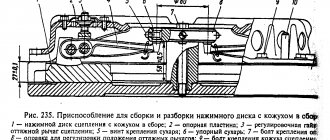
Installation of the T-170 clutch
Installation of clutch driven parts
Press the gear drum 7 (see Fig. 191) complete with bearings onto the crankshaft journal until it stops. Install the washer, locking plate, tighten the nut 6 with a socket wrench and lock it by bending the edges of the plate on the edge of the nut.
Install driven disk 9 on the outer splines of the gear drum, and drive disk 8 on the flywheel craters 10. Install the second driven disk on the splines of drum 7. The hubs of the driven disks should face the pressure disk.
Adjustment work
Correct adjustment of the tractor clutch is characterized by the presence of a gap between the bearing system and the release lever cams. It should be no more than 2-3 millimeters. When worn, the original properties are lost, which leads to weakening of the linings.
This also leads to other problems, which include slipping of the clutch when disengaged. If the gap exceeds the standard, it will be difficult to turn on the machine.
The connecting housing is equipped with a cover, when opening which you can perform the required diagnostic and adjustment work. The gap is changed by adjusting the screws connecting the bearing and the arms of the levers.
The clutch is adjusted by performing the following list of actions:
Additional Tips
The T25 tractor must be operated according to the instructions supplied with the machine. With the onset of the cold season, operating conditions become more difficult. Therefore, to ensure proper operation of special equipment, it is recommended to take into account the following tips:
To avoid negative consequences during self-repair, replacing the clutch on a T25 model tractor must be carried out in accordance with the rules described in the technical documentation or manual. Also, periodic contact with specialists for the purpose of a full technical inspection and diagnostic work is a mandatory procedure.
Procedure for adjusting and repairing a car clutch
To adjust the cable, you need to unscrew the nuts holding it, then remove the support plate and look at the force of its tension. Ideally, it should be at a height of 12 cm from the floor and located as much as possible inside the car. The clutch cylinder needs constant monitoring of its condition, because... This is one of the most important elements of the unit, untimely repair or replacement of which can lead to more serious malfunctions of the entire gearbox, chassis, or even the engine. Diagnostics and repair of clutch elements must be carried out at the slightest manifestation of a malfunction and, of course, at visible mechanical damage. But no less than once every six months. This is necessary in order to quickly and reliably fix all problems, as well as ensure the safety and comfort of the driver behind the wheel.
In order to qualitatively examine the condition of the car’s clutch and all its components, specialized tools and equipment are required. All the necessary technical equipment is available only at the service station, which is why people go there for a thorough inspection and repair work.
Service stations should be visited regularly to avoid rare but expensive repairs. In general, clutch repairs can be done quite inexpensively if you contact specialists in a timely manner. The BestWay car service will take into account all your wishes and features. We also provide a guarantee on all clutch repairs and replacements for up to 1 year or 30 thousand miles, which allows you to protect yourself from poor-quality repairs.
Source
Gearbox and clutch repair
T-25 tractor clutch repair:
- Disconnect the rod from the lever by removing the pin.
- Release the clutch pedal from the action of the spring by screwing the stop bolt into the bracket and lowering the bolts to allow the bracket to move freely.
- Set the free play of the pedal on the pad to 0.4-0.45 cm.
- Place the bracket in the upper position and tighten the fastening bolts.
- Unscrew the stop bolt and return the pedal to its original position.
- Turn the lever counterclockwise until it stops.
- Adjust the length of the brake rod and connect it to the lever. After these steps, you can pin the pin and tighten the locknuts securely.
Repair of the gearbox of this tractor model:
- It is necessary to replace the bevel gears in the hydraulic distributor drive.
- Adjust the range shift and reverse locking mechanism.
The locking mechanism is adjusted as follows:
- The rod is disconnected from the locking roller lever.
- Fully depress the clutch pedal.
- Install the locking roller so that the axis of symmetry of the roller lever coincides with the pointer on the compartment cover.
- Connect the rod to the lever and check the adjustment by turning on the reverse ranges.
- Seal the pin and tighten the locknuts.