How does the MTZ clutch work? What do you need to know to adjust it correctly and how to do it correctly?
Belarusian tractors of the MTZ brand use a variant of the clutch system of the well-known permanently closed model, which has proven itself well on tractor and motorcycle equipment. One of the most important parts of the entire system remains the clutch, which transmits torque to the transmission from the diesel engine, disconnecting it from the gears and smoothly (soft) connection. The clutch on tractors of the MTZ - 80 and MTZ - 82 brands has one disk and is dry, which allows you to guess about the main parts of this part.
Right. This is a pressure plate and flywheel installed in the grooves of the support disk on three protrusions. The pressure plate is secured to the flywheel using spacer bushings, pins and nuts. In special cups, between the pressure plate and the support plate, there are twelve pressure springs that set the clutch in motion. With the help of axes, release levers are installed on the protrusions of the pressure disk, and when acted upon, the entire mechanism is turned on.
Clutch - operating principle
Adjustment of the clutch is carried out by releasing its stroke. This is done with adjusting screws that change the position of the release levers. The screws themselves rest against the support pins and are screwed into the levers, which in turn are pressed against the pins by springs.
The so-called torque vibration damper (torque shaft damper) is connected to a driven disk, consisting of a hub with splines for joint mobility and secured by three linings. One of the linings is fixed directly to the disk with brass rivets, the other is attached to the pressure plate with steel rivets through spring plates.
This clever design of the driven disk is capable of engaging the clutch quite smoothly and accurately due to axial compliance during rotation. The torque of the diesel engine is transmitted to the hub from the driven disk through springs, and the clutch is engaged or disengaged by a release bearing. The branch moves along its own bracket, connected by a lever, a rod and two forks secured to the shaft with keys and clamps.
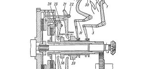
Clutch diagram:
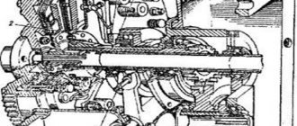
1 - flywheel; 2 — driven disk assembly; 3 — pressure disk; 4 — clutch spring cup; 5 – clutch pressure spring; 6 — support disk; 7 — driven disk hub; 5 - damper; 9 — supporting disk; 10 — spring plate; 11 — friction lining; 12 — restrictive disk; 13 — release lever; 14 — support pin; 15 - axis; 16 - finger; 17 — bushing; 18 — castle nut; 19 — spring; 20 - lock nut; 21 — adjusting screw; 22 — bearing; 23 — clutch outlet; 24 — layering bracket; 25 — intermediate gear; 26 — drive shaft of the PTO drive; 27 — power transmission shaft; 28 — brake lifting bracket; 29 — power fork shaft; 30 — power plug; 31 — brake release; 32 — drive brake disc with lining; 33 — clamp spring; 34 - ball; 35 — reduction gear shift lever; 36 — gearbox hatch cover; 37 — fork lever; 38 — drive gear of the reduction gearbox; 39 — needle bearing; 40 — gear coupling; 41 — needle bearing; 42 — driven shaft of the PTO drive; 43 — coupling; 44 PTO drive shifts; 45 — bronze bushing; 46 — driven gear for second stage PTO drive; 47 — driven gear of the first stage PTO drive; 48 — fork; 49 — clutch lever; 50 clutch release shaft; 51 — oiler; 52 - plug; 53 — clutch housing.
Basic problems and options for correcting errors in operation
The only malfunctions of this tractor unit, naturally, remain purely mechanical ones, which appear due to wear of certain parts or due to contamination and improper operation, when the leaf clutch is not able to operate smoothly:
- Violation of the required standard adjustment.
- Excessive and abundant oil on the discs.
- Loosening and stretching of pressure springs.
- Wear of linings between discs.
If there is obvious slippage, the first thing you need to pay attention to is the accuracy of its adjustment , but if this does not help solve the problem, then you need to drive the tractor a little, warming up the disks, then stop and turn off the diesel engine, shifting the gearbox lever to the neutral position, and climb into the housing, removing from the casing the hatch cover.
Then pour half a liter of gasoline inside and crank the crankshaft several times, thereby cleaning and washing both discs. This is done with a regular medical syringe, the jet of which is directed onto each disc until completely cleaned. After rinsing, close the housing with the lid and you’re done.
However, if washing does not give a positive result, this indicates significant mechanical wear of the disks themselves and weakening of the pressure springs. Consequently, these parts must be dismantled and replaced with new ones.
Finally, the second important cause of problems is incomplete shutdown due to excessively increased pedal travel. Here, too, everything is done by the usual adjustment of the brake and rod connecting the pedal to the locking shaft.
Features of self-repair of the MTZ clutch basket. Adjustment and replacement information
Tractor clutch parts, like any other wheeled mechanism, fail over time. This process is accelerated by slipping and incomplete gear disengagement. The MTZ-82 clutch basket, disc and other parts need periodic repair or even replacement.
Direct clutch adjustment
The clutch in Belarusian tractors of the MTZ - 80 and MTZ - 82 brands is adjusted by the free play of the pedal and the length of the brake locking rod, and if these elements are fully interconnected, the adjustment must be carried out in parallel and simultaneously, in the following sequence:
- Pull your finger out, disconnecting the brake traction.
- By tightening the stop bolt completely so that the bracket moves freely, you should be able to release the pedal and clutch from the action of the spring.
- You set the free play of the pedal (this is from 40 to 45 mm) by changing the length of the rod.
- Return the bracket to the highest point, turning it around the axis until it rests against the bolt, and then tighten the mounting bolts.
- After unscrewing the stop bolt, return the pedal to its place, all the way to the floor. In this case, the release spring should instantly return the pedal back.
- If the pedal does not return, you need to move the bracket around the axis again and loosen the bolts a little.
- By moving the lever clockwise all the way and connecting the brake rod to it, tighten its length a little (by 7 mm.
- After completing all steps, securely secure the assembly with locknuts.
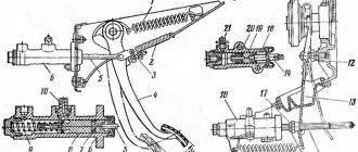
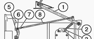
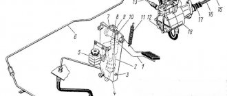
Clutch control circuit:
1 — pillow rod; 2 - bolt; 3 — clutch pedal; 4 - axis; 5 - spring; 6 — thrust bolt; 7 — bracket; 9 - traction; 10 - fork; 11 — lever; 12 - fork; 13 - thrust; 14 - spring; 15 - lock nut; 16 — lever; 17 - bolt.
Tips and recommendations for care during use
The unit must be lubricated every 60 operating hours, and the free play of the pedal must be checked at least every 240 operating hours . For lubrication, grease is used, used according to the lubrication table. Free play may decrease over time due to natural wear of parts, and the maximum reduction in travel due to wear should not exceed 30 mm.
Well, the main thing:
- Do not keep your foot on the pedal while the tractor is running (this increases the rate of wear).
- The clutch engages smoothly. There is no need to leave it in an intermediate state.
- The clutch release clutch should not be disengaged for a long time.
Check and possible malfunctions
Like any moving mechanical unit, the clutch is subjected to strong and serious workload during operation, which sooner or later leads to failures and breakdowns.
It doesn’t take much intelligence to determine that the clutch system of a Belarusian tractor is functioning properly. Remember two main signs of its high-quality work:
- When the clutch is operating, the discs do not slip relative to each other, sending regular force from the diesel engine;
- When you depress the pedal, you should immediately feel that the clutch is completely disengaged.
It is necessary to check and inspect the clutch system every third maintenance (technical inspection), paying special attention to the transmission of torque from the diesel engine. That is, carefully inspect the clutch every 960 operating hours of the tractor.
The check is carried out simply: the tractor is driven onto a flat, straight surface, where it is started in any gear, setting the crankshaft speed to an average level, and then the machine is stopped and, if the diesel engine stops working after stopping, then everything is fine with the clutch, and if the engine only slows down the rotation of the crankshaft, then the problem is that the clutch slips.
Troubleshooting
Wear and failure of clutch parts can be determined by the appearance of:
- difficulties when changing gears;
- extraneous noises and knocks;
- clutch slipping.
If a strong noise or whistle occurs when you press the clutch pedal, most likely the release thrust bearing has failed. As for slippage, its main cause is oil getting on the discs due to leaks through the gearbox or crankshaft shaft seals.
During operation of the tractor, cracks and rainbow colors may appear on the surface of the pressure plate. This is due to worn linings and bent clutch discs.
Clutch malfunctions of the MTZ 82 tractor
1 Poor gear shifting with a grinding noise or inability to engage a gear. By squeezing the control pedal, the clutch is not completely disconnected.
Cause : Increased free play of the clutch pedal as a result of incorrect adjustment.
2 When the clutch is smoothly engaged, the tractor begins to move with a jerk.
Cause : Loss of damper springs or rubber bands from the driven friction disk of the mechanism.
3 Clutch slipping when the traction load on the tractor increases or the engine speed increases.
Cause : Incorrect adjustment - lack of pedal free play; wear of the friction linings of the driven disk; oil getting on the clutch discs as a result of a leak in the oil seal of the main bearing of the engine crankshaft, or oil seals in the tractor transmission.
Adjusting the position of the release levers of the MTZ 80(82) clutch
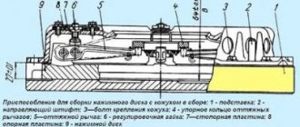
Adjustment is carried out during assembly with the basket installed on the engine and the transmission housing disconnected. Adjusting the position of the release levers of the driven friction disk of the clutch consists of setting the gap between the flange of the splined hub of the clutch basket support disk to the working surface of the lever-claws. The gap is set by tightening the adjusting screws of the feet and should be 12 mm. To ensure uniform squeezing of all paws, the gap difference should not exceed 0.3 mm. This adjustment ensures the position of the working surfaces of the squeezing pads in the same plane, which gives the friction disk uniform contact of its working surface with the engine flywheel, eliminating distortion and uneven wear of the disks when turning on and off.
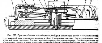
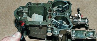
You can check the adjustment using a flat plate or piece of glass. By applying the plane to the paws, check that all points of contact with the paws are in the same plane parallel to the flywheel. To facilitate the installation of the clutch mechanism on the engine flywheel and subsequent adjustment, experienced repairmen use a centering false shaft simulating the diameter of the gearbox shaft splines and the working plane 2 of the release bearing (in the figure). This device ensures the coaxial position of the flywheel and clutch discs during installation, and the simulating plane of the release bearing simplifies the adjustment of the paws. The device can be made from appropriate used ones. shafts of the tractor transmission intermediate box.
Repair
If, when operating the MTZ-82 tractor, you can hear gears grinding while shifting gears, it means:
- clutch discs are worn out;
- The control mechanism is not adjusted correctly.
After troubleshooting and adjusting the clutch, the grinding noise should disappear. If this does not happen, then you need to start adjusting the mechanism that tensions the brake spring. You can check the correct setting of this mechanism by the length of the compressed spring - it should be 31-32 millimeters.
Is the problem still there? This means that it is necessary to remove the cabin floor, as well as the cover of the reduction gearbox and the hatch of the coupling basket. Having done this, measure the thickness of the disc linings - it should be at least 1.5 mm. Otherwise, the brake disc should be replaced. To do this, disconnect the clutch housing from the gearbox, roll out the tractor island and remove the cover of the reduction gearbox. After this, all that remains is to dismantle the clutch shaft using technological bolts, and then replace the brake disc.
Diagnostics of mechanism parts
To diagnose the condition of the coupling, you need to gain access to the unit. To do this, disconnect the engine from the transmission and roll out the tractor. Then an initial inspection of the unit is performed. Then unscrew the six nuts securing the basket to the flywheel and dismantle the assembly for a full inspection.
Release bearing condition
The bearing is replaced: the contact surface is worn out, it is noisy when rotating and has play in the races, the bearing is jammed.
Practitioners recommend that, in addition to the original bearing of the MTZ 80 tractor, you can install a KamAZ 5320 release bearing, which has proven itself in the operation of the tractor clutch mechanism.
When worn out at the contact areas of the bearing and fork drive, the parts can be restored by welding metal, followed by processing to the appropriate size.
Condition and degree of deterioration of the working surfaces of the feet and their integrity
When the working surfaces of the legs exceed 2.5 mm, they are replaced or welded on with subsequent processing.
When installing new paws, you need to pay attention to the contact plane of the levers with the release bearing. Often, castings of levers have non-identical contours and a contact surface; when applied to a bearing, they protrude beyond the working surface, capturing the part holder. In this case, the protruding part is ground off. When replacing paws, you also need to pay attention to the degree of metal hardness. One of the reasons for the rapid erasure of the feet after repair is the mismatch of the material used or the lack of hardening of the working surfaces of the part.
Condition of the foot springs
If broken springs are identified, all three springs are replaced.
Condition of the basket hub splines
If the splines are sufficiently worn or hub play appears, the basket is replaced.
Friction disc condition
If cracks, uneven wear, lifting of the linings, wear of the hub splines and play, loss of damper springs, as well as sufficient wear of the linings are detected, in all cases the disc is replaced.
Condition of the working plane of the basket pressure plate and the mounting holes for the paws
In case of uneven wear of the pressure plate, leveling by milling and grinding is allowed, taking into account the tolerance of the disk thickness of at least 21 mm. If the mounting holes for the release levers are broken into an ellipse, or if cracks are detected, the disc is replaced with a new one.
Flywheel contact plane condition
If acceptable ellipse of the flywheel surface is determined, alignment is carried out by milling and grinding. If the surface is worn too much, it must be replaced.
After defect detection of parts has been carried out, based on the condition, a decision is made: to carry out routine repairs of the unit with the replacement of worn parts or to replace the assembled unit.
Correct installation of the clutch disc on MTZ 80(82)
- The driven friction disc is installed with the side with the extended part of the hub facing the engine flywheel, otherwise the damper springs will touch the heads of the flywheel mounting bolts.
- The clutch basket assembly is installed on six flywheel mounting studs with bushings.
- Align the clutch mechanism with a prepared false shaft or used one. shaft gaps.
- The six nuts securing the basket to the flywheel are tightened and the positions of the paw levers are adjusted.
- The transmission and engine are connected to the clutch mechanism by placing the shaft splines into the clutch hub splines.
- The connection between the housing and the engine crankcase is tightened.
If you are installing a new clutch mechanism, you must remember to unscrew the three technological mounting bolts from the basket body.
When communicating with professional machine operators, it is often discussed that the success of a repair depends on the quality of the spare parts purchased for replacement. There are a lot of products of dubious quality on the market. When selecting and purchasing, you need to pay attention to the compliance of the linear dimensions of the parts, seats, and the compliance of the material of manufacture, its hardening or carburization, grinding, if necessary, balancing.
Source
Adjusting the MTZ 82(80) clutch, paw clearance and disc installation
Full adjustment of the clutch is carried out during repair or replacement of the mechanism, as well as during assembly after repair of the engine or mechanisms of the tractor transmission. Correct clutch adjustment ensures the transmission of torque from the engine to the transmission without loss of generated power, and also creates conditions for changing gears of the tractor gearbox and PTO mechanisms. Evidence of the correct operation of the clutch and control drive is the absence of slipping of the disc when the clutch is engaged, and the complete separation of the transmission from the engine when the clutch pedal is depressed.
Adjustment can only be carried out on a working mechanism, taking into account the technical condition of the parts and tolerances in the joints.
Correct adjustment of the clutch of the MTZ 82(80) tractor is done in two stages:
- Installing the release levers relative to the basket hub
- Adjusting the clutch pedal free play
