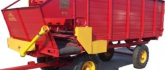
The mounted model RU-1000 has a bunker volume of one cubic meter and a spreading width from 12 to 28 meters. RU-1600 differs from RU-1000 in the volume of the bunker.
The trailed model RU-3000 has a hopper volume of 2.8 m3, a spreading width from 12 to 28 meters. A drive from a power take-off shaft is used.
The most powerful model of the RU-7000 spreader can be used not only for applying fertilizers, but also for transporting 7 m3 of fertilizers. The drive of the discs is carried out from the power take-off shaft of the tractor, as well as from the rear wheel of the trailer. Setting the spreading width and the amount of fertilizer applied is carried out manually. Spreading width from 15 to 28 meters.
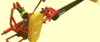
The MMT-4U model can be used not only for applying fertilizers, but also for transporting 4 m3 of fertilizers. The discs are driven from the tractor power take-off shaft. Setting the spreading width and the amount of fertilizer applied is carried out manually. Spreading width from 8 to 24 meters. This unit can also be used for applying de-icing mixtures in the winter in road and municipal services. For these purposes, an additional set of guides and disks is available.
A special chemicalization vehicle MAZ MHS-10 is used to transport and spread 12 tons of fertilizers. Spreading width from 8 to 32 meters. The use of an all-terrain chassis ensures maximum mobility and ease of use of the spreader.
Optselmash
The Rostov plant Optselmash specializes in the production of machines for agriculture. Its catalog contains both trailed and mounted models.
You may be interested in:
Organic fertilizer spreader: description, application rules
Potato planter for walk-behind tractor: principle of operation, how to do it yourself
Cultivators for inter-row tillage: types and description. Instructions for making a cultivator with your own hands
The Farmer series of spreaders is represented by four models (950, 1200, 1500, 2000), differing in hopper volume (from one to two cubic meters). The spreading width is adjustable from 10 to 36 meters.
The Pro series of spreaders is represented by three models (2000, 2500, 3000), differing in hopper volume and trailer options. Models Profi 2000 and Profi 3000 have two axles, models 2500 and 3000 are made in a single-axle version. The hopper volume is 2, 2.5 and 3 m3, the spreading width is adjustable from 10 to 36 meters. The discs are driven from the tractor power take-off shaft.
Rostov plant AgroTech
The Rostov Agrotech plant produces four models of spreaders S-1500 (MVU-1500), MVU-600, MVU-900 and MVU-1200. All of them are of the mounted type.
Model S-1500 is designed for spreading fertilizers, as well as for sowing grain crops and green manure. The volume of the bunker is 1.5 m3 due to extensions and increases by another 0.5 m3. The spreader is controlled by a hydraulic drive. The spreading width is adjustable from 6 to 36 meters.
Models MVU-600 and MVU-900 differ in hopper volume. MVU-600 has a bunker with a volume of 0.54 m3, MVU-900 - 0.82 m3. The spreading width is adjustable from 8 to 24 meters. The spreader is controlled by a hydraulic drive.
The MVU-1200 model has a bunker volume of 1.2 m3. Unlike MVU-600 and MVU-900, the model has a double-disc spreading system and a high-power mechanism. It is used for applying all types of fertilizers, seeds, sand. The spreading width is mechanically adjustable and can be from 12 to 36 meters.
The L-116 spreader model is produced by Lidselmash OJSC. The hopper capacity is 0.5 m3, the spreading width is mechanically adjustable from 8 to 24 meters. There is a modification of the spreader for applying a sand-salt mixture to roads in winter.
The Polish manufacturer of agricultural machinery UNIA Group Sp.zoo produces two lines of mounted spreaders MX and MXL and a trailed model RCW. Both mounted models can be used both in the basic mounted version and in the trailed version, placed on the Kastor chassis. In addition to their main use, UNIA spreaders can be used for sowing grain crops.
The MX spreader models are produced with hopper volumes of 0.85, 1.2, 1.6 and 3 m3. Designed for use with tractors with power from 60 (MX 850) to 180 hp. (MX 3000). Spreading width from 8 to 36 meters. Equipped with a hydraulic system for dosing the amount of spread fertilizer. For ease of use, they can be equipped with transport wheels.
The MXL spreader models are produced with hopper volumes of 1.2, 1.6, 2.1 and 3 m3. Designed for use with tractors with power from 60 (MXL 1200) to 180 hp. (MXL 3000). Spreading width from 8 to 36 meters. Equipped with a hydraulic dosing system for the amount of spread fertilizer controlled by a UTS computer. They can be equipped with discs for more precise spreading of fertilizers, as well as transport wheels.
RCW spreader models are produced with hopper volumes of 3, 5.5, 8.2 and 10 m3. Spreading width from 8 to 36 meters. Designed for use with tractors with power from 40 (RCW 3000) to 120 hp. (RCW 10000). The spreader mechanism is driven from the rear wheel of the trailer, which makes it possible to ensure the rotation speed of the discs as uniformly as possible. If necessary, for more precise application of agrochemicals, the RCW can be equipped with a Superior computer.
GÜSTOWER Norti GD-8L
The German GUSTOWER spreader is made of a semi-trailer type. Hopper volume 7 m3, spreading width 10-36 meters. The spreader mechanism is driven from the rear wheel of the trailer.
BOGBALLE
The Danish company Bogballe specializes in the production of various mounted and trailed equipment for agricultural work, producing a whole line of spreaders. The smallest spreader of the S series is used to spread sand on street sidewalks, the largest of the M series has a huge five and a half cubic meter hopper.
The S series is equipped with a hopper with a capacity of 0.25 to 1 m3. The main purpose of the series is to work in public utilities by adding sand to roads and sidewalks, but these micro-spreaders can also be used in small areas. Spreading width from 1 to 8 meters. Mounted spreaders can be installed on a special chassis and used in a trailed version. The disc drive operates from the tractor power take-off shaft or from a hydraulic pump. The adjustment mechanism is controlled by the ICON calibrator system.
The L series is equipped with a hopper with a capacity of 0.5 to 2.5 m3. Spreading width from 10 to 18 meters. To adjust the amount of spread fertilizer, ICON or ZURF calibrators are used, which use an on-board computer and a bunker fullness sensor for their work. Data about the work done can be read onto a USB drive.
The M series is equipped with a hopper with a capacity of 1.25 to 4 m3. With the help of extensions, the volume of the bunker can be increased to 5.5 m3. Spreading width from 12 to 42 meters. The M series can be used in both mounted and trailed versions using a special chassis. To adjust the amount of fertilizer spread, a ZURF calibrator is used, which uses an on-board computer and a bunker fullness sensor for its work. It is also possible to use manual control of disk speed using hydraulics. The disc drive operates from the tractor power take-off shaft or from a hydraulic pump.
The German company Kuhn produces two lines of spreaders - MDS and AXIS. Both models are mounted type spreaders.
The MDS model is equipped with a bunker with a volume of 0.5 to 0.9 m3; with the help of extensions, the maximum capacity of the bunker increases to 1.8 m3. Spreading width from 10 to 24 meters. The disc drive operates from the tractor power take-off shaft. The main components of the model are made of stainless steel. Manual, hydraulic or electronic adjustment of the supply of fertilizer to the discs is possible.
The AXIS model is equipped with a hopper volume from 1 to 3 m3; with the help of extensions, the maximum capacity of the hopper increases to 4 m3. Spreading width from 12 to 50 meters. The disc drive operates from the tractor power take-off shaft. The main components of the model are made of stainless steel. The spreading width and the amount of fertilizer applied per square meter of surface are controlled by the QUANTRON-E electronic device
RockMelt Fertilizer Spreader
The RockMelt manual fertilizer spreader trolley is designed for uniformly spreading any bulk substances over the soil surface: mineral fertilizers, small plant seeds, sand, de-icing agents and is ideal for both spreading mineral fertilizers in the summer and for sprinkling sidewalks with sand in the winter. The plastic bin holds 22 liters of fertilizer. Wheels with wide tread will not get stuck in any loose soil. The fan spreading mechanism operates from a drive wheel. On the handle of the trolley there is a ten-position switch for adjusting the amount of fertilizer poured out.
Handjgreen 2 fertilizer spreader
Manual fertilizer spreader Handjgreen 2 fan type. The bunker holds 2 kilograms of fertilizer, which is practically enough to fertilize an entire hundred square meters of garden plot. The model is made of durable plastic, has an ergonomic handle, and is designed for use in a small garden.
There are many models of mineral fertilizer spreaders produced in the world, and every farmer, be it the owner of a small bed or the head of a huge agricultural holding, can choose a mechanism to suit his taste and budget that will help him grow a bountiful harvest.
Ivan, 30 years old
Our field is small - 20 hectares, and the Belorussian tractor has an L-116. And the mechanism is light weight, inexpensive and works quickly and well. And in the winter, when there is less work on the field, the administration and I entered into an agreement to clean the roads. When snow falls, we clean the roads, and when icy conditions begin, we spread sand along the roads with the L-116. This is how a good device feeds us both in winter and summer.
Anastasia, 35 years old
We have a small lawn in front of the house, we planted it with lawn grass. To keep the grass even and tender, it must be fertilized evenly. Previously, we tried to scatter mineral water manually - it came out either thick or empty. Either the grass grows sad and small, or an overdose of fertilizers directly burns the grass. And then on occasion we bought a Handjgreen 2 manual fertilizer spreader, we couldn’t be happier! And you can plant and scatter small seeds evenly without any problems, and spread the fertilizer evenly! Of course, it’s not easy to carry two kilograms in a bunker, but we fill half a bunker at a time - and it lasts a long time and is easy to carry! A handy thing is a manual fertilizer spreader!
Nikolay, 45 years old
And in our agricultural holding we use the ZA-M profi spreader from Amazon. Convenient device! In the cabin, you enter the type of fertilizer and the application rate per square meter into the computer - the spreader itself calculates and does the rest. And how accurately he places chemicals along the edge of the field - evenly, not a crumb flies onto the road. It works very economically. Of course it cost us a lot, but it’s worth the money!
Types of Fertilizer Application Machines
Agricultural machinery for applying fertilizers is divided into the following types:
- Machines for applying organic fertilizers;
- Machines for applying mineral fertilizers;
- Machines for applying liquid organic fertilizers.
Organic fertilizer application machines
Special multifunctional trailers with high load capacity, which can be used all day long without downtime.
This machine delivers organic fertilizers to the application site and itself applies it to the soil. The machine can be used for return delivery of cargo, which underlines the versatility of this equipment.
Machines for applying mineral fertilizers
The mineral fertilizer spreader is widely used in agriculture to apply solid or liquid minerals in crystalline and granular form, and this equipment can also be used to fertilize meadows and pastures with minerals.
Photo: Trailed mineral fertilizer spreaders RUM 2500
Machines for applying liquid organic fertilizers
The most functional machine, which is used not only for surface and subsoil application of liquid organic fertilizers, but also performs the following functions: transporting water and liquid cargo, washing equipment and preventing fires.
Mounted disc spreaders
It is impossible to give descriptions for all brands of spreaders; in this article we will try to talk about the general principles of operation, technical characteristics and rules for adjusting the seeding rate of units. What should you pay attention to first when purchasing equipment?
Centrifugal (disc) spreaders
1. What tractors are they coupled with? Most spreaders for small farms or private farms can work with 14 kN class tractors. The power limitation is due to the different weight of the unit and the maximum capacity of the hopper for mineral fertilizers. Of course, over large areas, high-performance equipment is used, which is combined with powerful tractors.
Important. Make sure that the hitch on the tractor is compatible with the spreader frame. Most current tractors meet these requirements, but old Soviet equipment was manufactured according to different state standards. In such cases, you will have to purchase additional mounting elements.
2. Power take-off shaft speed. European standard 540 rpm. All the manufacturer’s adjustments are designed for this frequency; if the tractor has a different power take-off shaft speed, then when using the spreader you will have to independently determine the seeding rate through extensive experience. It is difficult, time consuming and costly. Almost all tractors have several shaft rotation speeds; these specific ones are indicated in the technical data sheet.
Mineral fertilizer diffuser SIPMA RN 500 BORYNA
Double disc spreaders RN 500 / RN 1000 BORYNA. Product type. File for download
RN 500 / RN 1000
Disc spreader "Promar". File for download
DISC FERTILIZER SPREADER promar-NO-14
What parameters are used to regulate the technical characteristics of spreaders?
Very important performance characteristics for users; selecting a specific model depends on the size of the field and the amount of fertilizer applied.
Fertilizer spreaders
- Working width. Impacts performance. But there are also limitations - in small areas it is difficult to maintain the sowing rate of fertilizers with a larger working width. For farms, a capture range of 12–24 m is recommended.
- Bunker volume. The larger the volume, the less often you will have to leave the field to fill the fertilizer bunker. Any detour from the track not only significantly reduces labor productivity, but also leaves an unnecessary mark on the ground or seedlings. In addition, it is almost impossible for the tractor driver to continue sowing with the same accuracy as until the end of the mineral fertilizer bin. You should not purchase spreaders with a hopper volume of less than 0.9 m3. But you need to keep in mind that not all tractors will be able to transport overly heavy bunkers. For tractors of the 14 kN class, the total weight of the equipped mounted spreader must not exceed 1500 kg.
- Operating speed and power take-off shaft speed. These two characteristics are closely related to each other; taking into account their values, the sowing rate of fertilizers is established. For small farms, the tractor should have an operating speed range of 8–18 km/h. Do not confuse them with transport speed, the final one is much higher.
Spreader - photo
What mechanisms does the spreader consist of and how does it work?
All disk-type mounted units have a similar design; the differences may be insignificant and relate only to some aspects of increasing labor safety and adjustment accuracy.
Trailed, mounted 2-disc mineral fertilizer spreader Ferti – 2
The spreader consists of a metal frame with a hopper, several mechanisms for adjusting the seeding of fertilizers, a drive gearbox and disks. There can be two or one disk, they work in turns or simultaneously. Some of the most modern models have special mixers inside the bunker for additional preparation of fertilizers for sowing and improved cleaning of the bunker from residues. Such devices make it easier to maintain and operate the unit. The top of the bunker is covered with a grille, which prevents the entry of large, hard pieces of compacted fertilizer.
The mechanism for adjusting the amount of fertilizer consists of two elements: a control valve (the number of fertilizers falling on the disks depends on the width of the gap) and a shut-off valve (serves to completely close the hopper during transportation). To prevent spontaneous changes in the position of the dampers, there are clamps.
Mounted mineral fertilizer spreader Jar-met
A mechanical tedder is located inside the bunker, ensuring a measured flow of mineral fertilizers to the gates. The granules then fall onto the spreading discs. They are equipped with special blades that capture portions of fertilizers and, under the influence of centrifugal forces, scatter them over the ground. For measured spreading over the entire working width, there is an additional adjustment of the blades; the specific position is selected taking into account the seeding rate, the characteristics of the fertilizer and the operating speed of the tractor. All moving parts are driven by a power take-off shaft.
ZA-X Perfect mounted fertilizer spreader
Adjustment algorithm
The mechanism is adjusted taking into account the stage of work (normal or late application) and the method of spreading (right or left of the field edge). Moving the spreading vanes across the discs changes the working width and spreading method.
The typical height of the disks above the field level in the absence of plants is 80 cm; if planned feeding of growing plants is carried out, then the height of the disks should be increased by half the length of the vertical stem. To make adjustments easier, most spreaders have factory tables attached near the discs. With their help, you can complete all preliminary installation work much faster.
It is better to determine the seeding rate of fertilizers experimentally - it has a very complex dependence not only on the type, but also on the actual state of the granules, and ready-made tables are not very suitable. Such operations are carried out in several stages.
Determination of application dose
The tractor is placed on a smooth platform, measures are taken to prevent its spontaneous movement. Both disc spreaders must be removed and any fertilizer collection device must be installed under the spreader. Open the dosing flap and find out how much fertilizer is poured out within one minute. Having a dose, you can calculate the actual amount of fertilizer applied per hectare of field.
Next you need to find out the exact speed of the tractor across the field. To do this, you need to drive one hundred meters in working condition and measure the time, using signs or calculated lines to determine the actual speed of the tractor. To simplify calculations, most manufacturers fix special metal plates with speed indicators on the surface of the bunker.
Next, more complex calculations begin - determining the actual amount of fertilizer applied, taking into account the speed of the tractor, the working width and the amount of fertilizer recommended by agronomists for a given crop. Well-known manufacturers make this work much easier by installing various scales. If this information is not available, then you will have to make calculations using the formula:
Specified Working Width Recommended
number spreading speed quantity
output = tractor, km/h × fertilizer, m × fertilizer, kg/ha
fertilizers —————————————————————————-
(kg/min) 600
Much. During work, you need to remember that when the operating speed of the tractor increases by 10%, the number of fertilizers applied decreases by 10%.
As you can understand, the adjustment and setting of the application dose should be carried out by a competent specialist, preferably under the supervision of an agronomist.
Mineral fertilizer spreader room 5
Safety precautions
A very important topic that, unfortunately, many do not pay attention to. In addition to the generally accepted applications for working with agricultural attachments, there are several specific ones:
- It is strictly forbidden to be within the spreading area of fertilizers during work;
- all repair and technical service activities must be carried out only with the engine turned off;
- Before starting work, you should undergo introductory training and carefully study the instructions for use
Remember safety precautions when operating equipment
MAIN TECHNICAL CHARACTERISTICS MVU-5 (RUM-5)
| Options | Meaning |
| Productivity (at an implement speed of 12 km/h), ha/h, not less: - when adding granular materials - when adding crystalline materials - when adding powdered materials | 14,884 |
| Working speed during main operations, km/h, no more than 15 Working width, m: - when adding granules. materials - when adding crystal. materials - when adding powdered materials | 14-2010-148-12 |
| Transport speed, km/h, no more | 25 |
| Range of application doses, kg/ha | 100-1000 |
| Maximum loading height (from the ground surface), mm, no more | 2500 |
| The number of personnel required to service operations directly related to the operation of the machine, | 1 |
| Machine dry weight, structural, kg | 2060 |
| Overall dimensions, mm-length-width-height | 535021522000 |
| Load capacity, kg, no more | 5000 |
| Track, mm | 1800 |
| Ground clearance, mm, not less | 350 |
| Drive of working bodies: - conveyor - dispersing bodies | VOMVOM |
| Basic aggregation | MTZ-80 |
| Tires (size) | 12-16 |
| Tire air pressure, MPa | 0,25 |
| Distribution along the axles at full weight: - along the axles - on the hydraulic hook of the tractor | 12005860 |
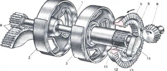
Device
The metal frame is equipped with a drawbar and a loop for attachment to the tractor. The five-ton welded body, where fertilizers are poured, is part of the frame. There is a plate-and-rod type conveyor located inside the body. It is driven either by the tractor power take-off shaft (if more than six tons of fertilizer is applied per hectare), or (with less fertilizer) by a shaft located inside the axle shaft of the right rear running wheel.
The conveyor delivers the bulk mass to centrifugal-type seeding discs, each of which is equipped with four blades with grooves fixed perpendicular to each other. The movement on them comes from the tractor PTO. The transmission of motion involves a cardan, bevel-type gearboxes, V-belt-type profiles and satellite shafts.
To ensure that fertilizers are unloaded more evenly, the body has a bimetallic fertilizer guide panel installed on the side supports. The dosing gate, moving on skids at the rear of the body, is controlled by a steering wheel mounted on the shaft. Two sprockets that engage with the slats allow you to adjust the height of the damper.
The chassis is a trolley with balancers, designed as a “tandem” type and without springs. The split-type wheel is attached with six studs and nuts to the hub, which has a drum for braking. The unit has two types of brakes: mechanical (intended for braking while parking) and pneumatic, single-line. The latter is controlled from the tractor cabin by a pedal. You can manually brake using a crane. At the same time, the front wheels stop.
There is a plug for connection to the tractor's electrical system. Alarm devices are connected with a separate wiring harness. There are two lights at the rear of the unit.
RUM-5 spreader diagram
1 - bunker; 2 — feeder: 3 — drum-chopper; 4 - counter plate; 5 - separating device; 6 - rotor; 7 - conveyor
STRUCTURE AND OPERATION OF THE MVU-5 (RUM-5) MACHINE
The MVU-5 (RUM-5) mineral fertilizer spreader is a semi-trailer equipped with a transporting and one or two centrifugal-type dispersing working bodies.
The components of the machine are:
body with frame; drive of working parts; conveyor; dispersing centrifugal disks; metering valve; fertilizer guide;
The drive of the working bodies can be carried out, depending on the model, from the running wheel of the machine, the PTO of the tractor, or the hydraulic system of the tractor. The working parts of the machine are controlled from the tractor cabin. To regulate the flow of scattered material, there is a metering valve, which is controlled by a steering wheel located on the left side of the machine.
The principle of operation of the machine is as follows: materials intended for application are poured into the body of the machine using foreign means. When the machine is operating, materials are fed through a dosing window and a fertilizer guide onto centrifugal disks, which disperse them in a fan-shaped flow to the surface.
Design features:
The car body is made of metal, all-welded design, made together with the frame. The frame consists of two longitudinal spars connected by cross members, and a drawbar with a trailing loop.
The chassis of the MVU-5 (RUM-5) machine is a springless tandem-type balancing trolley, consisting of two balancers connected by a central axle on plain bearings, with axles for mounting the wheels. Inside the body there is a device for uniform unloading of fertilizers, which is a three-dimensional bimetal screen mounted on two supports mounted on the front and side sides.
The metering valve of an improved design is a gate that moves in guides on the rear side of the body using a steering wheel mounted on the shaft together with two sprockets that engage with the slats on the valve.
The machine's rod-plate conveyor consists of straight rods connected in a closed chain using link plates. The drive of the conveyor at application doses up to 6000 kg/ha is carried out from the running wheel, over 6000 - from the tractor PTO.
The scattering discs have four grooved vanes mounted at right angles to each other. To increase strength, the discs are equipped with flanges and annular corrugations. The drive of the discs is carried out from the tractor PTO through a cardan shaft, intermediate shafts, two V-belt circuits and two bevel gearboxes.
A split disc wheel is attached to the hub using six studs and nuts. A tire (310X406 GOST 7463–75, mod. L-163) is mounted on the wheel rim. A brake drum is installed on the hub.
The MVU-5 (RUM-5) machine has two independent brake drives: pneumatic and mechanical (parking). The pneumatic drive of the semi-trailer brakes is made according to a single-wire circuit and is activated when the tractor brake pedal is pressed. The valve for manually controlling the semi-trailer brakes is designed to release the brakes of the semi-trailer when parked when the connecting line of the semi-trailer is disconnected from the connecting line of the tractor. The parking brake only serves to slow down the vehicle when parked. The front wheel brakes are used as the parking brake of the vehicle.
The drive of the working parts of the machine is carried out from the PTO of the tractor and the running wheel of the machine. It consists of a scattering disc drive and a conveyor drive.
The drive of the scattering devices is designed to impart rotational motion to the scattering disks. The conveyor drive is made from the right rear running wheel of the machine and is carried out by a drive shaft passed inside the wheel axle shaft. To apply doses over 5000 kg/ha, the conveyor drive is converted to operate the conveyor from the tractor PTO by connecting a block consisting of a pipe with toothed disks, which is attached to gear hubs of the central shaft of the gearbox using a chain and protective covers.
The electrical system includes: two rear lights, a plug and a bundle of wires connecting the spreader signal devices to the tractor.
The product is certified and issued by PSM for registration with Gostekhnadzor.
Rice.
1. Spreader RUM-3: 1 — chassis; 2 — body; 3 - conveyor; 4 - gearbox; 5 - dosing device; 6 — fiber divider; 7 — disks; 8 - windproof device. The dosing device consists of two divider pipes and a dosing sowing valve.
The fertilizer divider is designed to divide the fertilizer flow into two parts and direct them to the spreading discs. The design of the fertilizer dividers allows you to change the location of fertilizer supply to the centrifugal discs, which makes it possible to adjust the spreading range.
The windproof device improves the uniformity of spreading fertilizer in windy weather and consists of two wings, which are tubular frames covered with dense rubberized material.
The fertilizer sowing rate is set by changing the speed of the conveyor and the height of the seeding slot by moving the damper lever along the sector scale.
The conveyor speed is controlled by changing the crank radius from 20 to 80 mm. There are corresponding divisions on the side of the crank.
The 1-RMG-4 spreader is equipped with a hydraulic drive of the working parts. Unlike the body of the RUM-3 machine, the body of the 1-RMG-4 spreader holds 3.5 tons of fertilizers.
The feeding conveyor is an endless chain of wavy rods. The curved ends of the rods, which engage one another, move with their sharp ends against the machine, which prevents fertilizer from sticking in the guide grooves of the conveyor and prevents it from floating. The conveyor is driven from the left running wheel of the spreader through a rubber-coated pressure roller, which is pressed against the wheel by a hydraulic cylinder. Such a drive maintains the rate of fertilizer application regardless of the speed of the machine.
The hydraulic cylinder is connected to the hydraulic system through a pressure stabilizer, which makes it possible to obtain a constant pressing force on the roller, independent of the movement of the sprung running wheel of the machine. When working on a wet grass field, it is recommended to wear a snow chain on the road wheel.
From the pressure roller to the drive shaft of the feed conveyor, the movement is transmitted by chain transmissions. The drive allows you to obtain two speeds of movement of the feeding conveyor—1.3 and 6.16 m/min. When placing a sprocket with a number of teeth of 2=10 on the pressure roller, and a sprocket with a number of teeth of 32 on the intermediate roller, the conveyor speed will be 1.3 m/min; if a sprocket with a number of teeth of 2 = 25 is installed on the roller, and a sprocket g is installed on the intermediate roller - 17, then the conveyor speed will be 6.16 m/min.
The dosing device is made in the form of a sectional gate of the slide type, moving in the grooves of the rear side of the body using a lever-hinge mechanism. A ruler is installed on the groove indicating the opening height of the sowing slot in millimeters. The right spreading disc 6 is rotated by a hydraulic motor powered by the tractor hydraulic system. The left spreading disc 6 is driven into rotation from the right one by a cross V-belt drive.
Rice. 2. Spreader 1-RMG-4:
Fertilizer dividers that direct fertilizer to the spreading discs and regulate the uniformity of fertilizer distribution across the working width are the same as those of the RUM-3 spreader.
The amount of fertilizer applied is regulated by changing the position of the metering valve and the speed of movement of the feeding conveyor. At a fertilizer application rate of less than 1000 kg/ha, the conveyor speed should be 1.3 m/min; at a rate greater than 1000 kg/ha, 6.16 m/min.
Installation of mounted spreaders. The machines are coupled with tractors of traction classes 6, 9 and 14 kN and are designed for continuous application of mineral fertilizers and their mixtures in fields and gardens, as well as for scattered sowing of grass seed. The NRU-0.5 spreader can apply fertilizers at rates from 40 to 2000 kg/ha, the RU-4-10 machine - from 50 to 1165 kg/ha.
The NRU-0.5 spreader consists of a frame (Fig. 3), a hopper with a arch-breaking device, a dosing device, a sowing mechanism, spreading discs and a drive mechanism.
The frame is welded from metal pipes. In the front part of the frame there are brackets for mounting on a tractor, in the rear part there is a towing bracket for towing a trailer with fertilizers.
The bunker is made of sheet steel and has the shape of a truncated pyramid, tapering downwards. To prevent large lumps from entering when loading fertilizers, the top of the bunker is covered with a mesh with cell sizes of 35X35 mm. When working in windy and rainy weather, the bunker is covered with an awning. Windows were made to control the amount of fertilizer in the bunker. On the front and rear walls of the bunker, arch breakers are installed that perform a reciprocating movement.
The dosing device consists of two valves, with the help of which the height of the front and rear sowing slots is changed. The position of the valves is fixed using a lever and a gear sector. The valves are equipped with spring shock absorbers, which protect them from damage when large solids get into the cracks. Along the bottom of the bunker, from one seeding slot to another, a zigzag-shaped seeding bar oscillates. With its active cutouts, it pushes fertilizer through the front and rear slits. The bar is attached on suspensions to the crank mechanism; the amplitude of the bar's oscillations is regulated by changing the length of the drive's rocker arm.
Fertilizers ejected from the hopper are delivered to two horizontal disks with radially arranged grooved blades. The discs rotate at a frequency of 562 rpm and, under the influence of centrifugal forces, scatter fertilizer across the field. The drive mechanism transmits torque from the tractor power take-off shaft through a cardan shaft with a safety clutch to all spreader mechanisms. From the power take-off shaft, the movement is transmitted to the shaft of the main bevel gearbox, and from it the crank, connecting rod and rocker arm drive the oscillating shaft. Vibrations from the shaft are transmitted to the arch breakers and by suspensions to the sowing bar. By rearranging the connecting rod on the rocker arm, you can change the vibration amplitude of the sowing bar and arch breakers. From the main shaft of the bevel gearbox, through a chain drive and bevel gearboxes interlocked with chain couplings, the movement is transmitted to the spreading discs.
Rice. 3. Scheme of the NRU-0.5 spreader:
The RU-4-10 spreader has a roughly similar device. The hopper is made of sheet steel and has the shape of a truncated cone, at the bottom of which, at the smaller base, there is a small cylindrical part. The top of the hopper is closed with a lid consisting of two halves: fixed and hinged. The cover is held in the open position by latches. At the bottom of the bunker there is a hatch for cleaning, and on the front wall there are two viewing windows at different heights to control the amount of fertilizer. The bottom of the bunker is installed at some distance from the lower base. The size of the gap between the base of the hopper and its bottom is regulated by a movable annular damper, moving along the cylindrical part of the hopper using a regulator lever mounted on a gear sector. At the bottom of the bunker there is a metering device in the form of a rotating finger ejector, which pushes fertilizer into the sowing slot. The fertilizers released from the sowing slot are funneled into a centrifugal six-bladed spreading disc rotating at a frequency of 810 rpm. To prevent the formation of arches or freezing of fertilizers in the bunker, a turner is installed in it, consisting of a rod with teeth welded to it and driven by the ejector shaft. When loading the bunker with fertilizers, the turner is in a vertical position, coinciding with the longitudinal axis of the bunker. This is achieved by the fact that the upper end of the turner is connected by a cable to the opening lid.
The spreader's working parts are driven by the tractor's power take-off shaft. By rearranging two movable blocks of gears on the input and output shafts of the drive gearbox, you can change the gear ratio and thereby obtain different rotation speeds of the ejector and agitator. To regulate the amount of fertilizer applied, the transmission is provided with four gear ratios and corresponding four rotation speeds of the ejector; 12.0; 22.5; 36.0 and 67.5 rpm.
When spreading fertilizers in windy weather, a windproof device consisting of two wings is installed on the machine. Each wing is a frame made of pipes, on which rubberized fabric is stretched.
Features of the vehicle spreader device. The spreader is installed on the chassis of a ZIL-MMZ-555 dump truck and is a one-piece body with a capacity of 3.2 m3, at the bottom of which a fruit conveyor moves, the same as that of the 1-RMG-4 spreader. The small diameter of the conveyor bars (10 or 12 mm) allows you to reduce the seeding gap between the bottom and the metering valve and increase the minimum fertilizer application rate to 50 kg/ha; The maximum fertilizer application rate is 6000 kg/ha.
The spreader conveyor is driven from the inner slope of the left drive wheel of the vehicle by a pressure roller with a pneumatic tire. Therefore, the fertilizer application rate remains constant regardless of the speed of the vehicle. The roller is mounted on a rotating frame and is pressed against the car wheel by a hydraulic cylinder through a spring shock absorber. The hydraulic cylinder is included in the hydraulic system of the tip-over device of the dump truck body. From the pressure roller, the movement is transmitted by chain transmissions to the drive shaft of the feed conveyor. The conveyor is tensioned by moving the driven shaft in the front part of the body. With replaceable sprockets with a number of teeth r-12 and 2=25, two conveyor speeds can be obtained. For small rates of fertilizer application (50-1000 kg/ha) use an asterisk g=12, for large rates (1000-6000 kg/ha) use an asterisk 2=25.
The rate of fertilizer application is adjusted by changing the height of the sowing slot by acting on the metering valve. The position of the damper is determined by a ruler attached to the side. The KSA-3 machine has one spreading disc with a fertilizer guide. Rotation is transmitted to the spreading disc by a hydraulic motor from the hydraulic system of the dump truck. When applying small rates of fertilizers (up to 600 kg/ha), especially granular ones, a cone disc is installed instead of a flat spreading disc. The use of a conical two-tier spreading disc instead of a flat spreader, where Qmm is sowing of fertilizers in 1 minute, kg; V—unit operating speed, km/h; B—width of the processed strip, m.
If ff differs from the specified norm, then change the size of the sowing slot. The machine is finally adjusted to the specified rate of fertilizer application in the field during the first passes of the unit.
Installation of dust fertilizer spreaders. For transportation, self-loading and pneumatic unloading or sifting of mineral fertilizers, lime, and gypsum across the field, automobile and tractor spreaders are used.
The ARUP-8 automobile dust fertilizer spreader is an EIL-130V1 automobile tractor equipped with a compressor unit driven by a power take-off, and a tank semi-trailer based on the S-927 cement tanker with a folding support device for installing the tank in a position uncoupled from the tractor. Inside the tank there is an air terminal for pneumatic unloading and a fertilizer level indicator. Spraying and shut-off devices are mounted at the rear of the tank. To improve maneuverability across the field in the autumn-winter period, wheels with arched tires are installed on the semi-trailer and the rear drive axle of the vehicle.
The chassis of the semi-trailer is equipped with pneumatic brakes driven by the pneumatic system of the tractor and a parking brake.
Self-loading with fertilizers occurs pneumatically using a special loading pipe and a hose with an intake nozzle, a rotary compressor operating in vacuum pump mode, and a fertilizer level indicator.
During unloading, the air supplied to the air bottom passes through the porous partition, aerates the material, facilitating its flow to the unloading hatch and entry into the spraying device.
The RUP-8 tractor pulverized fertilizer spreader consists of a tractor-tractor equipped with a compressor unit driven by the tractor power take-off shaft and a fifth wheel device, and a semi-trailer tank with a spraying device, unified with the tank of the ARUP-8 machine. The fifth wheel coupling is equipped with a lock for semi-automatic coupling and uncoupling of the tractor with a tank semi-trailer.
Rice. 4. Spreaders of dusted fertilizers: a — automobile spreader ARUP-8; b — tractor spreader RUP-8.
To rotate the sawing device branch pipe and open and close the plug valve, the spreader is equipped with a hydraulic system.
The compressor unit is mounted on a tractor and includes a rotary compressor (the same as on the ARUP-8 spreader), a moisture-oil separator, filters for cleaning dusty air, a compressor frame, a drive mechanism, a vacuum meter and connecting pipelines.
Tank semi-trailer wheels with arched tires.