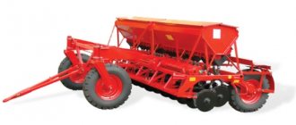
Agricultural farms engaged in livestock farming must be provided with feed for the winter period. In addition to preparing hay for large and small livestock, succulent feed is also prepared - silage and haylage.
To ensure that succulent feed is prepared quickly, special forage harvesters are used for mowing crops. The production of such combines began a long time ago. Their task was to mow or select succulent forage crops from windrows, chop them and load them onto a transport platform or trailer.
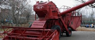
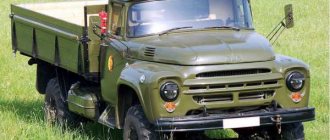
Forage harvester E-281
In Soviet times, both domestically produced forage harvesters and foreign equipment were used in the fields. One of the popular foreign forage harvesters was the E 281 model produced by the GDR company Forshtritt. And although this company has already ceased to exist, the combines it produced are still in operation. In addition, the design of the E 281 was so successful that it is still being produced, but by domestic companies and under a different designation - “Maral 125”.
Features and benefits
The main feature of the E 281 combine was its high productivity and the ability to mow and process forage crops over large areas. At the same time, he could harvest crops both with a certain row spacing (silage corn) and continuous crops (grass).
The use of several types of headers made it possible to use E-281 forage harvesters for both dry hay and straw harvesting.
The advantages of the E 281 silage harvester were obvious:
- The use of a powerful power unit ensured high performance;
- The use of several types of headers made it possible to use it in different types of harvesting of forage crops;
- The design of the combine ensured the supply of crushed forage crops to a considerable height;
- Small dimensions ensure high maneuverability;
- The design of the combine was simple, which ensured high reliability.
If we talk about the disadvantages of the E 281 combine, it is now difficult to find some spare parts for the power plant. As a way out of the situation, power units from domestically produced tractors began to be installed on these combines. Otherwise the combine is reliable.
Photo of the E-281 combine (Maral-125)
Forage silage harvester E-281: technical characteristics, design, photos and videos
Types and features of the design of combines for harvesting feed
Depending on the autonomy of the power plant, forage harvesters are:
- self-propelled – they move using their own diesel engine and wheeled or tracked chassis;
- trailed - articulated with the drive unit through a towbar or power take-off shaft. Aggregated with powerful tractor equipment such as MTZ;
- semi-mounted - common in small agricultural firms and households, where they work in tandem with small mini tractors or even walk-behind tractors.
The diagram shows the typical internal structure of all forage harvesting machines, according to which they distinguish:
- 1 – separating elements;
- 2 – blades;
- 3 – reel;
- 4 – screw devices;
- 5-7 – feeders – usually 4- and 5-roller mechanisms are presented, some of them can be spring-loaded;
- 8 – plate;
- 9 – crusher;
- 10 – conveyor;
- 11 – guide pipe;
- 12 – spreader.
The principle of their operation is in many ways reminiscent of the operation of a classic grain harvester. Thanks to the dividers, the segment on which the bevel will occur is outlined. The knives cut the stems, which are picked up by platform headers. The harvested mass, passing through the grinding compartment and the auger, is fed to the feed rollers, the main function of which is to press and evenly lay the grass before final crushing. In drum or disk crushers, the spikelets are cut into uniform pieces, which are poured through silos into trucks.
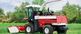
Forage harvester "Jaguar" 850
A modification produced by the German brand “Claas”. It is characterized by reliable technical equipment and decent performance properties, which made it one of the most popular combine harvesters in the world. Adapted for mowing herbaceous crops and long-stemmed crops of varying ripeness. Thanks to the pick-up, it turns into a unit for making silage from dried windrows.
- powerful power plant with a good torque reserve;
- special design of V-shaped knives, which have a self-sharpening mechanism activated from the cabin;
- “CORN CRACKER” functionality, which is involved in additional crushing of the crop due to 100 teeth;
- silo pipeline with a rotary range of up to 190 0;
- hydraulic drive of the drive axle;
- fuel supply system with filter;
- “STOP ROCK” – stone detection technology to protect rotating organs;
- cabin with climate control.
Technical characteristics of the Jaguar 850 combine:
- Power – 303 kW;
- Header – 3 m;
- Cutting – 4…17 mm;
- Number of rollers – 4;
- Speed parameters – 16..40 km/h.
The brainchild of the famous Polesie brand, which differs from other models in its affordability and low resource intensity of production. It has a universal set of options that allow you to prepare silage and haylage with high quality, quickly and with maximum comfort for the combine operator. In an hour of continuous operation, such a machine can produce up to 108 tons of silage material and up to 39 tons of fresh feed.
- chevron arrangement of cutting elements with a shift in two rows;
- 5-roller feeding device with hydromechanical drive and finger reversal;
- adjustable cutting height, allowing you to mow down fallen grains, low-growing grasses and long-stemmed plants;
- functionality for copying terrain irregularities;
- reduced feed losses due to clamping mechanisms and a spring-loaded auger;
- built-in metal and stone detectors;
- extended range of rotation of the silo pipeline.
What differs from the previous model is the absence of an auto-sharpening mechanism and lower operating and transport speeds.
Operating parameters of KSK-600:
- Power – 235 hp;
- Reaping block – 3/5 m;
- cutting height – 6…30 cm;
- Fuel tank – 0.4 m3;
- Speed – 12…20 km/h;
- Weight – 7.8 tons.
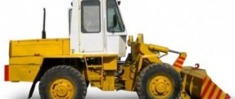
Forage harvester KSK-100A
Forage harvester from, now known as “Polesie”. Appeared on the basis of the main model KSK-100, the production of which was suspended in 1986. Equipped with a 200-horsepower engine unit. It is based on a feed part with a 5-roller mechanism and a drum chopper.
- ease of operation;
- simple design diagram, which simplifies repair work;
- a cabin glazed on all sides for good 360° visibility, complemented by rear-view mirrors;
- 6-cylinder engines - SMD-72 or YaMZ-238;
- low specific resource consumption per unit of harvested mass;
- rear-wheel drive, providing excellent cross-country ability on sandy soils.
Among the disadvantages of this machine it should be noted:
- unsuitable for work in wetlands and wet soils;
- unprotected drum from stones and foreign objects;
- unsuitable for fine grinding;
- imperfect chassis.
- Power – 200 hp;
- Diesel consumption – 162..168 g/hp. in an hour;
- Productivity – up to 25 kg/s;
- Harvesting speed – up to 12 km/h;
- Cut – from 6 cm;
- The length of the workpieces is 5…100 mm.
A trailed model, which is driven by the tractor's PTO and can be used for harvesting corn, sunflower, cereals, and legumes - fresh or dried in windrows.
The design of its shredder is based on a disc shredder. It is also equipped with sensors to prevent the ingress of stones and metal objects.
- an improved disc crusher with 12 radially arranged blades that effectively grinds the vegetative part of plants and hard grains;
- long service life of the feed rollers due to stone and metal detection;
- a universal trailer unit that allows you to change the traction base with little time and effort;
- compactness, facilitating storage and transportation on public roads;
- extended product warranty that lasts 24 months.
- Tractor power class – not lower than 2nd;
- Required power – 110…185 kW;
- Productivity – up to 43 t/h;
- Capture – 2/3/3.4 m;
- Cutting height – 6/12 cm;
- Weight – 3100 kg.
Forage harvester "Rostselmash" RSM 1401
New generation forage harvesting unit. It combines high labor productivity, high quality and precision of grinding, economical consumption of fuels and lubricants and ergonomic design. Its technical properties allow it to cover 18 km of field in 1 hour of field work and produce 140 tons of silage.
- direct-flow feeding of stems into the chopper;
- V-like localization scheme for knives, sharpening of which is carried out automatically;
- a large optional selection, including equipment with a roller grinder, a preservative substance distributor, a lubricant distributor, and video surveillance functionality;
- body for a worker “Comfort Cab” with 2 seats, which has built-in air conditioning, stove, refrigerator;
- panoramic windshield with a tinted layer for better visibility;
- information module “Adviser”, which controls the technological process with voice recording.
Device
Structurally, the E 281 combine consisted of two parts - the main machine and working units. The main vehicle was self-propelled, with front-wheel drive and rear-wheel drive. The combine had a rear-mounted power plant. In front of the power plant there was a cabin.
The main vehicle was driven by a diesel engine. Also, part of the effort was taken from it to bring the working units into operation. For this purpose, there were two pulleys on the crankshaft, and both the combine and the working unit were driven by means of belt drives.
A V-belt variator was used as a gearbox, which transmitted force from the power plant to the driving front axle, while the speed and direction of movement were changed using the variator.
The combine was controlled by a hydraulic steering mechanism. The combine cabin was designed for one person. Changing the direction of movement was carried out by the steering wheel. The operating mechanisms were turned on and off using a remote control. The header position was controlled using a multifunction joystick.
Scheme of the E-281 combine
1 - pick-up drum; 2 - auger; 3 — lower front roller of the feeding apparatus; 4 — upper front roller; 5 - lower second roller; 6 - upper second roller; 7—lower fifth roller; 8 - upper third roller; 9 – grinding drum; 10 - silo pipeline
Working units
The working units of the E 281 combine consisted of two parts: attachments (reaper) and a chopping unit included in the design of the main machine.
Several headers were used on the E 281 and they all had their own designation. One of the harvesters had the designation A 22. It was intended for the selection of withered and dry forage crops, which had previously been mowed and folded into a windrow. It consisted of a housing, a picking drum, an auger feeding the crop into the grinding unit, and drive mechanisms for the drum and auger.
The second header had the designation A 42. Structurally, it was identical to the A 22 header, but its dimensions were larger and it was intended for the selection of mowed dry and dried feed, located either in a wide windrow, or it was used to select two windrows at once.
For harvesting silage corn, the M 30 header was used; this header was the main one for the E 281. It consisted of a body, a fingerless segmental scythe, a reel, belts for feeding the cut crop to the feed auger, the auger itself and drive mechanisms.
The fourth header, used on the E 281, was designated S 42. This header was intended for harvesting short and medium-sized grass crops. It consisted of a body, the braid was segmented, fingerless. A reel was installed in front. The cut crop was fed into the chopping unit by an auger.
The chopping unit consisted of feed and feed rollers, which received the crop from the header, pre-pressing upper and lower rollers, and pressing rollers. Passing through all these rollers and rollers, the crop was pressed and fed into the cutting drum housing, where the crop was crushed. A discharge channel was also connected to the cutting drum body. A silo line was connected to the unloading channel, through which the crushed crop was removed from the combine.
The combine consists of a chassis, a diesel engine, a chopper-loader and replaceable working parts: a pick-up and headers for harvesting herbs and tall crops. The main technical data of the combine are given in the appendix.
The chassis is a frame with a front axle of driving wheels and a rear axle of steering wheels. A diesel engine is mounted on the frame, feeding and crushing devices with a loading mechanism and a silo line, a platform and operator's cabin, a hydraulic system, electrical equipment, a steering drive mechanism and other drive and transmission mechanisms.
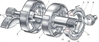
The driving wheel axle (Fig. 1) consists of variator half-pulleys, a clutch, a gearbox with a final drive and differential, axle shafts, final gearboxes and wheels. The gearbox has three forward and one reverse speeds.
Rice. 1. Kinematic diagram of the main machine: 1 - diesel; 2 — drive of the grinding apparatus; 3 - intermediate shaft drive; - 4 - intermediate shaft; 5—reversible gear drive; 6 — hydraulic pump drive; 7—variator drive pulley; 8 — variator belt; 9 — movable disk of the driven pulley of the variator; 10 - fixed disk; And, 13 - driven discs of the clutch; 12, 14 — clutch drive discs; 15 — pressure disk; 16 — pressure bearing; 17, 20, 21 — gearbox shafts; 18, 19 — blocks of movable sprockets; 22, 27, 31 — valr>1 differential and final drive; 23 — differential housing; 24, 26 — differential gears; 25 — satellite axis; 28 — brake pad; 29— brake drum; 30, 32 — connecting sleeves; 33 — driving *al of the final drive gearbox; 34 - gear; 35 — wheel axle; 36 - reversible clutch; 37, 38, 39, 41 — reversible gearbox shafts; 40 — movable gear block; 42 — drive circuit of the feeding apparatus; 43 — safety coupling of the feeding apparatus; 44, 45 — feed apparatus drive sprockets; 46, 62 — drive shafts of the feeding apparatus; 47, 54, 59—upper rollers; 48, 52 — drive chains of the upper rollers; 49, 50, 51, 53, 56 — drive chains of the lower rollers; 55, 57, 58, 60, 61 - lower rollers; 63 - chopping drum
Rice. 2. Grinding apparatus: 1 - drum; 2 - drive pulley; 3 — drum shaft support; 4 - key; 5 — shaft assembly; 6 — oiler; 7 — knife support; 8 — nut M16; 9, 16, 17, 22, 23, 27 — washers; 10 — M16 bolt; 11 - knife; 12. 15.18— M12 screws; 13 — spring plate; 14 — M12 nut; 19 — right frame side; 20 — concave; 21 — M10 bolt; 24 — nut L110; 25 — support for the cutting beam; 26 - M16 screw
The steering axle is a beam with wheels mounted on it, a transverse rod and swing arms. The bridge beam is pivotally connected to the frame using an axle.
Wheels with pneumatic tires are attached to hubs, which are mounted on tapered roller bearings of the steering axles. The rotation of the bridge wheels is carried out by a hydraulic cylinder.
Diesel - four-stroke, six-cylinder, 125 kW. It is started by the starter. The radiator is protected by a mesh filled with crushed mass.
The feeding ailarat consists of a lower, three upper ribbed and four lower smooth feeders, rollers, a three-speed gearbox and a mechanism for pressing the plant mass. The feeding device is equipped with reverse motion for cleaning when clogged.
The grinding apparatus (Fig. 2) includes a drum to which up to 12 knives with throwing blades (knife supports) are attached. Each knife can be separately adjusted in relation to the shear bar, which is mounted on a support 25 and has four working edges. To sharpen the knives of the chopping drum, a manual sharpening device is attached to the top of the sides.
Rice. 3. Simplified diagram of the E-281C forage harvester with the E-294 pick-up: 1 - picking drum; 2 - auger; 3 — lower front roller of the feeding apparatus; 4 — upper front roller; 5 - lower second roller; 6 - upper second roller; 7—lower fifth roller; 8 - upper third roller; 9 – grinding drum; 10 - silo pipeline
Rice. 4. Control levers: 1 - turning the silo; 2—turning on the running variator; 3 - raising and lowering the reel; 4 — lifting and lowering the linkage; 5 — gear change, 6 — hand brake; 7 — foot brake; 8 — cutting length adjustment; 9 — raising and lowering the visor; 10 — reverse switching; 11—switching the clutch; 12 — opening and closing the radiator shutters; 13 — adjusting the engine speed; 14 — turning on the chopping drum
The silo pipeline (Fig. 3) consists of a discharge channel, a discharge deflector, a rotation mechanism, a visor and a visor control mechanism. The discharge deflector is turned with a hydraulic cylinder, and the visor is adjusted using a traction cable, a spring and a lever (Fig. 4) installed in the cabin. The crushed mass is sent through the silo wire to the vehicle.
The steering drive mechanism serves to transmit rotation from the steering wheel to the shank of the metering pump.
The metering pump drives the hydraulic cylinder of the steering wheel axle.
The hydraulic system of the power cylinders is designed to raise and lower the pick-up or headers, the reel of the header for harvesting corn, turn the silage wire and steered wheels and control the variator. The power cylinders are controlled by a hydraulic distributor.
The cabin is attached to the combine frame through rubber gaskets - shock absorbers. The cabin is equipped with: devices for creating a microclimate (thermal and noise insulation, a ventilation unit for supplying purified air, a floor mat), a sprung seat with soft cushions and a backrest, a front window wiper, and a rear-view mirror.
On the operator's platform there are control levers: turning the silo; turning on the running variator; raising and lowering the reel of the corn header; lifting and lowering the hitch; changing speeds; turning on the hand and foot brakes; cutting length adjustment; raising and lowering the visor; reverse switching; turning the clutch off and on; opening and closing radiator shutters; adjusting the diesel speed; turning on the chopping drum.
On the steering column (Fig. 5) there are: a battery charging indicator light; oil pressure indicator in the diesel lubrication system; handbrake warning light; trailer warning light; trailer brake pressure indicator; sound signal button; direction indicator; plug socket for a portable lamp; parking light switch; dipped and parking light switch; glow plug starting switch; starting heater control element; holes for installing switches; coolant temperature indicator.
The kinematic diagram of the drive of the main machine is shown in Figure 1. The common drive unit for the working parts and the drive axle is a diesel engine, connected through belt drives to the chopping drum 63 and the intermediate shaft. The intermediate shaft drives the feed apparatus through a gearbox 36-41 and through a belt drive the drive shaft of the headers and pick-up, and through the variator, clutch, gearbox and spur gear of the final gearbox - the drive axle.
The gearbox is provided
Rice. 5. Instrument panel: 1 - battery charging indicator light; 2 — oil pressure indicator in the engine lubrication system; 3 - hand brake warning light; 4 - trailer warning light; 5 — pressure indicator light in the trailer brake system; 6 — sound signal button; 7 — direction indicator; 8 — plug socket for a portable light bulb; 9 — parking light switch; 10 — switch for low and parking lights; 11 — glow plug switch for starting the engine; 12 — control of starting heater; 13— holes for installing switches; 14 - flashing indicator light; 15 - coolant temperature indicator
The pick-up is designed for collecting pre-mown and dried grass and straw from windrows up to 0.8 m high and no more than 2 m wide. It includes the following main components: frame, bath, transport auger, picking rake drum, rod clamping device and drive, consisting of a counter drive, V-belt and chain drives and a gearbox.
The picking rake drum includes a shaft with disks in which four rakes with spring teeth are fixed. Cranks with rollers moving along a guide track are mounted on the left trunnions of the rake. When rolling, the rollers, copying the profile of the track, set the spring teeth in a certain position, which ensures the supply of the selected mass to the auger. The auger is installed in spring-loaded supports and, depending on the layer of incoming mass, can move along the guides.
The drive from the main machine to the counter-drive of the pick-up is carried out by a cardan transmission. From the counter-drive, the rotational motion is transmitted by a V-belt drive and gearbox to the picking rake drum, and then by a chain drive and friction clutch to the transport auger.
To prevent damage to the picking rake drum when reverse is engaged, a single-acting clutch is built into the pick-up gearbox.
The continuous cut header for harvesting herbs up to 1.5 m high consists of a housing, an eccentric spring finger reel, a normal cutting device with two mowing knives with a double-sided drive and a cylindrical auger with spiral belts in the right and left directions.
The continuous cut header for harvesting corn and other tall crops includes a platform with a chain-slat conveyor and two active dividers, a reel, a normal cutting device and a narrowing auger.
Specifications
Detailed technical characteristics of the E 281 forage harvester are given in the table:
| Characteristics | Unit measurements | Indicators |
| Power point | type/brand | Diz., 6 VD 14.5 |
| Power | hp | 170 |
| checkpoint | type | V-belt variator |
| Number of gears (forward/backward) | PC. | 3/1 |
| Transport speed | km/h | 20 |
| Length (without header) | mm | 5640 |
| Height | mm | 3950 |
| Width (without header) | mm | 2740 |
| Ground clearance (lowest point) | mm | 295 |
| Shredded crop ejection height | mm | 3900 |
| Tank capacity | l | 185 |
| Working width of the header E 22 | mm | 2130 |
| Working width of header E 42 | mm | 4200 |
| Working width of the header M 30 | mm | 2870 |
| Working width of header S 42 | mm | 4270 |
The video shows the E-281 combine harvester at work:
Self-propelled forage harvester (Maral-125(M))
Production has been discontinued.
Designed for mowing grasses and hard-stemmed crops, selecting mass from windrows with chopping and loading into a vehicle. “Maral-125M” is an improved type of the E-281 forage harvester, which has proven itself well in Russia. It is equipped with a metal detector and a foreign body trap to protect the grinding unit from metal and other foreign objects.
The combine uses an extended silage pipeline that can be rotated by 200° and has a hydraulic drive for the ejection direction hood.
"Maral-125" provides a grinding process (cutting and ejection of feed mass) with a high efficiency and guarantees a nominal throughput of green feed - 60 t/h, dried feed - 43 t/h and corn for silage - 60 t/h. With good harvesting organization, Maral-125 can provide up to 15,000 tons of feed per year.
- Feeding unit. Eight feeding and pressing rollers ensure an optimal flow of harvested crop; the formed package is compact and easy to cut. The feeding apparatus of the Maral-125M forage harvester is equipped as standard with a metal detector (sensor on the lower feed roller) and a sensor for catching foreign non-metallic objects (sensor on the upper pressing roller). A system of 2 sensors provides reliable protection of the power supply.
- Grinding unit. The original design of the chopping drum, with knives running along the entire length, thanks to the tightening method of mowing, provides exceptional cost-effectiveness in operation, since it does not require an additional accelerator or air blower. The cut crop is transported directly to the unloading system. This results in high performance and low energy consumption. The chopping length is individually regulated by selecting one of 3 feeding speeds and the number of installed knives (maximum 12 knives).
- Regrinding system. A completely new active regrinding system “Megacracker” with sliding rollers and a grass channel does not require dismantling the system when working with hard-stemmed crops. When harvesting corn with the Megacracker regrinding system, grain crushing is 99%.
Optional equipment.
The Unicracker universal crushing device, which has become the second generation of a system of devices with flattening rollers. Thanks to the new form of crushing rollers, equipped with several meshing and replaceable conical disks, it is possible to increase the length of the crushing gap by more than 2.5 times with a constant roller width, as a result of which the Unicracker has a very high throughput. Therefore, Unicracker is able to universally produce high-quality feed from all types of grain crops.