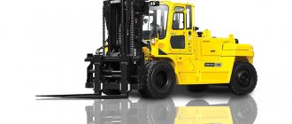
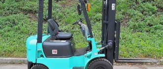
What else does a forklift transmission do:
- transmits torque to the wheels from the engine, as in most cars,
- controls the intensity of torque,
- sets the direction of movement,
- redistributes torque between the drive wheels.
Models vary, but in its classic version, this part consists of a drive axle, a cardan transmission mechanism (shaft) and a hydromechanical transmission mechanism. With the help of the reverse operator located in the cabin, the hydraulic-mechanical system is controlled, which sends a signal to the transmission mechanism, which, in turn, sets in motion the wheels or other working areas thus launched.
The principle of operation of a car transmission
You cannot install an engine under the hood of a vehicle, attach the clutch and wheels of the car to the crankshaft, and then just start driving. In this case, the design will not have enough power, which is needed to spin the wheels, since the main reason for this will be the friction force, the significant dimensions of the car and its weight. The way out of this situation is to install a special intermediate mechanism, which has the property of reducing the torque to the required number of revolutions, as well as transmitting all the necessary actions to the front wheels of the vehicle. As you understand, the mechanism described earlier is the transmission. Today we’ll talk in detail about this part of the car!
Description of transmission: device
Are you interested in a car's transmission? Then please note that this element of the vehicle consists of the following elements:
- clutch;
- drive shaft;
- Transmission;
- axle, which represents the main gear and differential;
- dispensing mechanism;
- CV joint, that is, a constant velocity joint.
Each of the elements that were listed a little above is an integral part of the car’s transmission, so a transmission malfunction may indicate a breakdown of any of the elements presented above. In addition, all components of a car transmission perform some important functions and are an integral part of the mechanism, thanks to which the car is able to move.
Principle of operation
Many car owners know for sure that any gearbox has several speeds at once. The transmission modes are truly varied. In this case we are talking about low speed, high speed and others that are intermediate. If you choose the lowest speed value, then the car’s transmission will have minimal impact on the car’s engine. The car will move slowly, which will allow you to speed up its movements at a certain moment, when you need to quickly move away and start moving.
If you turn on a high indicator on the gearbox, then in this case the rotational force will decrease and the speed indicator will increase. In general, speaking briefly, it is worth noting that you can drive modern cars with a manual transmission, which is represented by several intermediate speeds at once, without any difficulties, because the presence of several speeds at once guarantees that you will be able to cope with a wide variety of obstacles on the road. road.
So you've learned how the transmission works, but now let's talk a little about something else!
Transmission purpose
So, what is the main function and task of any transmission for a vehicle? The main purpose of a car transmission is to make it possible to convert power into so-called useful torque, which is transmitted to the wheels, making the movement of the vehicle possible.
In addition, thanks to this, the car not only starts to move, but can also constantly maintain a certain speed. In general, to put it briefly, it will become clear that without a transmission the car simply won’t go anywhere.
Transmission types
At the moment, experts distinguish the following types of transmissions:
- mechanical;
- electric;
- hydrovolumetric;
- combined.
What kind of car transmission do you need?
Signs of a car transmission malfunction
We have already discussed the principle of operation of the transmission in detail, but it is still not clear when you need to worry about a transmission failure. If the car owner is familiar with the components of the transmission, then if there are any signs of breakdown, he can try to fix everything himself. Here are the main signs indicating a malfunction:
- pedal sticking or sticking;
- the appearance of jerks when starting to move from a standstill;
- presence of fluid leakage in the place where the clutch wires are connected;
- presence of noise in the area where the clutch is located.
In addition, one of the signs may be a car slipping, so if you find any of the signs presented above in this article, then you should definitely undergo diagnostics and subsequently repair your vehicle so that it will serve you for a long time. many years.
Which oil should you choose?
If you are thinking about what kind of oil to pour into the transmission, then you should know exactly what three types experts divide oils into:
- synthetic;
- mineral;
- semi-synthetic.
If we compare synthetic-based oil with natural-based oil, it is worth noting that the former has better fluidity. In addition, the main advantage of synthetic products is the ability to use such oils over a fairly wide temperature range.
As for semi-synthetic products, it is obvious that they are something between synthetic products and mineral oils. Having paid attention to the properties of such oil, it is definitely worth noting that it is better than mineral products.
When discussing transmission oils, one cannot fail to mention mineral-based products. They are in high demand due to the fact that they have reasonable prices.
By the way, if you plan to change the oil in your car, you can also install a breather outlet kit along with it, which has a reasonable cost. Happy shopping!
off-wheels.ru
What types of forklift transmissions are there?
- Mechanical , simple and reliable. In such models, the front axle is connected to the driveshaft by a fork - this is the whole system. The simplicity of the “mechanics” makes it stable, practically impervious to breakdowns, but rather ineffective. Nowadays, such loaders are practically not produced; they have been replaced by easier-to-operate and more efficient equipment with hydromechanical and hydrostatic transmissions.
- Hydromechanical , where a torque converter is used instead of a clutch fork. Due to this, the traction power of the machine increases, and it becomes possible to work on it in harsh conditions: for example, at a construction site with uneven terrain, inclined surfaces, and the need to constantly carry loads up and down. A loader with a hydromechanical transmission is needed if the machine has to work frequently and for a long time with heavy loads in not the most favorable conditions.
- Hydrostatic - modern, which can be found on almost all self-propelled warehouse equipment in recent years. It does not have a gearbox, clutch, or shoe brakes, but it does have a whole closed hydraulic system that operates using hydraulic pumps with lines that connect them to each other. Loaders with such a transmission are controllable and maneuverable, they are well suited for installing all kinds of “smart” functions on them.
The choice of configuration depends on the specifics of the production where the loader will work. You can leave a request on our website - we will call you back at a convenient time and advise you on all issues related to the selection of warehouse equipment.
Forklift gearbox
Construction machines and equipment, reference book
Gearbox for loaders
K
category:
Loaders
Gearbox for forklifts
Two types of gearboxes (gearboxes) are installed on forklifts - reversible (forklifts) and non-reversible.
The reversible gearbox performs the following functions: a) provides the transmission with idle speed; b) provides a stepwise change in the gear ratio between the engine and the drive axle; c) provides the loader with operationally equivalent movement in the “forward” and “backward” directions - reversing movement.
Non-reversible gearboxes perform only the first two functions. To change to - . To control the movement of the loader, a separate reversing mechanism is installed - a reverse box.
Reversible gearboxes should not be confused with non-reversible gearboxes that have one reverse gear, while there are several gears for forward movement (automobile gearboxes).
Structurally, the gearboxes of the loaders under study are made in the form of multi-stage gearboxes, in which different pairs of gears can be put into operation. In the considered designs of gearboxes, two methods of such inclusion are used: using the device of sliding clutches with constant meshing of gear wheels; axial shift of individual gears, providing the possibility of variable engagement of gear pairs.
A gearbox with constant mesh gears is installed on forklifts. The gearbox is three-stage, reversible. It provides the loader with movement in three gears (three speeds) “forward” and “backward”. Carter - cast, cast iron. Its rear and front end parts are made in the form of flanges for connection to the clutch and drive axle.
Four splined shafts are installed in the housing in rolling bearings - drive (primary), driven (secondary), intermediate shaft and reversible. The drive and driven shafts are three-bearing. The toe of the drive shaft, through a bearing, rests on the toe of the driven shaft, made as one piece with a bevel gear, and through the bearing is connected to the inner housing of the drive axle.
The intermediate shafts are double-supported. Gears are connected to the shafts by flanges and rotate with them. The remaining gears rotate freely on the shafts on the bushings and do not have a permanent rigid connection with the shafts.
Two gear-type engagement couplings are installed on the drive shaft. The coupling is double-acting. It is designed to be alternately connected to the drive shaft of a gear or gear, and also has a middle neutral position.
Rice. 1. Gearbox for loader F17.DU32.33.1: 1 - crankcase, 2, 8, 9, 14, 16, 17, 19, 33, 35. 42, 43, 46, 53, 60, 61 - gears, 3 , 7, 24 and - seals, 4, 6, 10 - bearings, 5 - gear shaft, 11, 25, 48 - covers, 12, 18 and 38 - compressors, 13, 20, 39 and 41 - couplings, 15 - special nut, 21 and 34 - thrust bolts, 22 - plug, 23, 26, 28, 27, 55 and 62 - forks, 29 - slider, 30 - screw, 31 - spring, 32 - ball retainer, 36 - hub synchronizer, 37—primary shaft, 40—intermediate shaft, 44—reverse shaft, 45—spacer sleeve, 47—bearing cup, 50—adjusting plates, 51, 52 and 54—plugs, 56—vent, 57—cover, 58 , 59— fork shafts, 60—textolite gear
Rice. 2. Positional diagram of gearbox shifts: a – for “forward” movement, b – for “backward” movement
Single acting clutch. It has three main parts - a driving coupling half connected to the shaft by flanges, a driven coupling half made as one piece with a gear, and a sliding coupling half having a circular groove on the outside for connection to the switching mechanism. The toothed rims of the driving and driven coupling halves, as well as the internal teeth of the sliding coupling half, have identical profiles, which makes it possible to rigidly connect the driving and driven coupling halves to each other when the sliding coupling half moves to the right. In Fig. Figure 2 shows the neutral position of the clutch.
The coupling has a similar device, but the driven coupling halves are located on both sides of the drive, which allows you to alternately connect a gear or a gear to the shaft.
Structurally, the engaging clutches of the drive shaft are made in one unit with synchronizers.
Positional diagrams explain the order of operation of the gearbox parts when changing gears to move “forward”.
1st gear. The clutch is installed neutral. The clutch locks the gear wheel with the drive shaft. Torque is transmitted from the drive shaft to the intermediate shaft through a pair of gears from the intermediate shaft to the reverse shaft through a pair of wheels; from the reverse shaft to the driven shaft through a pair of wheels 9-2.
shafts. The maximum gear ratio of the gearbox will be in 1st gear (low gear, minimum loader speed). In second gear the gear ratio will have an average value, in third gear it will have a minimum value (highest gear), that is, the speed of the loader will be maximum.
It is necessary to pay attention to the following feature of the gearbox in question. Even in top gear, the gear ratio will be greater than one, that is, in the transmission, the gearbox also partially plays the role of the first stage of the main gear. Gears can be thought of as the first stage of the final drive.
In all three positional patterns, the directions of rotation of the drive and driven shafts are opposite, which corresponds to the forward movement of the loader. To obtain reverse gear, a parasitic gear mounted on the axle is engaged between the intermediate shafts.
The shaft has two gear-type engagement couplings. In the position shown in Fig. 2, the clutch locks the gears. When the clutch is engaged, the gears are locked together. At the same time, the clutch is moved to the neutral position. The gears are constantly connected to each other through an idler gear, which provides a change in the rotation of the intermediate shaft, and therefore the driven shaft.
In Fig. 3, b shows positional switching diagrams in the gearbox when the loader moves backwards. Schematically, the gear sequence can be depicted as follows: it is produced by switching forks rigidly fixed to the slide. In turn, the slider receives axial displacement from the primary fork, pivotally connected to the shaft. The slider has two fixed positions, which is ensured by two annular grooves at its end and a ball retainer. Its end positions are limited by thrust bolts.
The axial movement of the sliding coupling halves is performed by switching mechanisms. Reversing the gearbox.
Rice. 3. Gearbox for loaders 4043M and 4045M: 1 - lever, 2 - clamp, 3 and 4 - forks, 5 and 6 - sliders, 7 and 8 - gear block, 9 - bearing cover, 10 - driven shaft, 11 and 20 - ball bearings, 12 - axle, 13, 15, 16 and 18 - block of intermediate gears, 14 - crankcase, 17 - needle bearing, 19 - mobile block carriage, 21 - needle bearing, 22 - drive shaft, 23 - gear, 24 - crankcase cover
Clutch switching is performed by two forks pivotally connected to the shafts.
The gearbox is lubricated with liquid lubricant by spraying it from the oil bath in the crankcase. Lubricant is poured through the upper threaded hole, closed with a plug. The lower plug is opened to release the used lubricant. The side hole, closed with a plug, is designed to control the working level.
To improve the lubrication of the bushings and gears of the input shaft, a textolite gear is installed, which increases the efficiency of lubricant splashing in the crankcase. Lubricant leakage is prevented by installing flat gaskets under the flanges and a self-pressing seal on the driven shaft of the box.
The non-reversible gearbox of the 4043M and 4045M loaders is shown in Fig. 3. Its design is the same as that of the GAZ-51 car (without reverse gear). The gearbox is a four-speed one with coaxial drive and driven shafts and an intermediate shaft located parallel to them. Switching in the box is made by axial displacement of the gears on the driven shaft.
The drive shaft is made as one piece with the drive gear. The ends of the drive shaft rest on a ball bearing and on a ball bearing in the flywheel. There are flanges on the shaft for connection to the clutch driven disc.
The driven shaft is splined. A block carriage with gear wheels and a block carriage move along its splines.
The driven shaft is supported by a ball bearing and a needle bearing, which is located in the central hole of the drive shaft. A flange is attached to the splined shank of the driven shaft.
The block of intermediate gears rotates in needle bearings on the axle. The large gear of the block is in constant mesh with the drive gear.
The order of gear engagement is as follows.
Advertising:
Read more: Cardan shafts for
K
category: – Loaders
Home → Directory → Articles → Forum
stroy-technics.ru
Why does the gearbox fail?
Due to intensive use of the excavator, the load on its key components increases. How to find out that it is the automatic transmission that is suffering? It goes into emergency operation mode, an error message with a code appears on the vehicle’s dashboard, and the special equipment stops. Carraro diagnostics show what exactly led to the breakdown. Here are the most popular reasons:
- sudden acceleration and braking of equipment on slippery surfaces;
- wear of individual transmission parts;
- low-quality lubricants and other consumables;
- broken wires of gear position sensors;
- severe operating conditions not provided for by the manufacturer.
Problems with the transmission system can be found on the dashboard, where an error code is displayed. However, not all equipment models support this function. Then Carraro’s comprehensive computer diagnostics will help, in which specialists connect directly to the loader control unit and receive the information necessary to make a “diagnosis”.
TICKET No. 4. 1. The procedure for transferring motion from an internal combustion engine
1. The procedure for transmitting motion from an internal combustion engine. Design of transmitting nodes.
2. Purpose and list of daily maintenance work.
3. The procedure for approaching the load and bringing the forks under the load.
4. Causes of accidents and accidents at work. Injuries and occupational diseases, measures to prevent them.
1. The loader transmission is used to transmit torque from the engine to the drive wheels.
From the engine to the clutch, to the variable transmission (gearbox), to the driveshaft, to the drive axle.
— the clutch serves to transmit torque, briefly disconnect the engine from the transmission and smoothly connect them again. Comprises:
1. Drive part (flywheel, pressure plate, clutch cover)
2. Driven part (driven disk assembly)
3. Drive mechanism (can be mechanical, hydraulic)
— The gearbox is used to change the torque in magnitude, direction (reverse gearbox), as well as to disconnect the engine from the transmission. Comprises:
— the driveshaft serves to transmit torque at changing angles and distances. Comprises:
1. Two joints of uneven angular velocities
2. Spline connection (shaft, pipe)
Hydrodynamic transmission is used on most loaders and consists of:
1. Torque converter (transmits torque due to kinetic energy)
— the drive axle serves to increase torque and transmit it at an angle of 90⁰ to the drive wheels, consists of:
1. Main gear (single, hypoid, double, spaced with final drive)
2. Small-wheel differential (symmetrical gear)
3. Balanced type axle shafts
2. Daily maintenance is one of the main types of forklift maintenance and is carried out daily, regardless of the number of hours worked by the forklift.
Daily maintenance includes operations to prepare the forklift for work (departure) and care for it upon return to the garage.
— receive a task for the working day and instructions
- according to the shift log, check the comments of the previous shift on the loader and the implementation of these comments by the technical service
When preparing a forklift for work, you must:
— inspect the loader from the outside, check the completeness, presence of leaks, presence and quality of coolants, condition of the forklift, fastening chains, condition and inflation of wheels, condition of belts, serviceability of brakes, steering, operation of instrumentation.
Upon returning to the garage you must:
— clean the forklift and, if necessary, wash it;
— inspect the forklift and eliminate all detected faults;
— carry out the operations specified in the lubrication table.
— write down comments on the technical condition of the loader in the shift handover log
3. In order to correctly lift the load onto the forks, you must perform the following operations:
— before performing loading and unloading operations and transporting cargo, it is necessary to set the width of the forks of the loader in accordance with the dimensions of the cargo. Relative to the vertical frame, the forks should be positioned symmetrically, and their lower ends should be in the same plane.
— approach the load from the side most convenient for picking up the load on the forks, calculating the location of the load’s center of gravity as close as possible to both the front walls of the forks and the middle of the forklift carriage.
Purpose, design and operating principle of hydrodynamic transmission.
Modern loaders are increasingly using hydromechanical transmissions instead of mechanical transmissions. The hydromechanical transmission is designed to transmit torque from the engine to the drive wheels of the loader.
Composition of hydromechanical transmission:
— torque converter (hydrodynamic transmission);
-slow movement valve;
— gearbox with forward and reverse clutches;
The hydrodynamic transmission is structurally a torque converter, which is designed to transmit torque from the engine flywheel to the input shaft of the gearbox. Torque in such a transmission is transmitted by oil flow (in a manual transmission, torque from the engine to the input shaft of the gearbox through the clutch due to friction forces).
Operating principle of hydrodynamic transmission.
Torque from the engine is transmitted to the pump wheel, which is interlocked with the flywheel. This wheel drives the gear pump. The pump directs the flow of oil to the clutch control valves and to the pump wheel blades. The oil is thrown by the blades of the pump wheel onto the blades of the turbine wheel, which is mounted on the input shaft of the gearbox. Next, the torque is transmitted to one of the clutches, depending on the position of the reverse lever, and the drive axle.
The reaction wheel returns the oil flow from the turbine to the pump wheel, helping it rotate.
The hydrodynamic transmission allows you to smoothly (steplessly) change the torque. The magnitude of the torque depends on the oil flow, and this in turn depends on the crankshaft speed.
The design and operation of the steering control of a forklift. Troubleshooting and troubleshooting.
The steering control is designed to change the direction of movement of the loader.
Steering classification:
— mechanical with hydraulic booster;
Mechanical steering with hydraulic booster.
1. Steering column. 7. Pendulum lever.
2. Steering mechanism. 8. Transverse thrust.
3. Front longitudinal rod. 9. Pivot pin.
4. Hydraulic cylinder. 10 Ball joint.
5. Distributor. 11. Hydraulic lines.
The steering arms and rods are connected by ball joints.
Steering mechanism 2 is a gearbox with a worm gear, which increases the force on the output shaft by 5-10 times compared to the force on the steering wheel.
The hydraulic booster is a hydraulic cylinder 4 and a distributor 5, connected in one block.
Principle of operation.
When the steering wheel is turned, the front longitudinal rod 3 moves the distributor spool 5. The working fluid is directed into the corresponding cavity of the hydraulic cylinder, which acts on the rear longitudinal rod 6. This rod turns the pendulum arm 7, which is connected by transverse rods 8 to rotary axles 9.
Hydraulic steering.
In this type of steering, there is no mechanical connection between the steering column and the wheels. Hydraulic steering on loaders is combined into one hydraulic system with hydraulic drive of working equipment.
1. Steering column. 4. Hydraulic cylinder.
3. Pipelines. 6. Ball joint.
The hydraulic steering wheel is:
— guiding device – works as a distributor;
- dosing device - passes a certain amount of working fluid at a certain angle of rotation of the steering wheel.
Principle of operation.
When the steering wheel is turned, the working fluid flows through the distributor into one of the cavities of the hydraulic cylinder 4 located on the steering axle beam. The hydraulic cylinder rods are connected through rods 5 to rotary axles. The steered wheels are attached to the rotary axles.
The main malfunction of the steering is increased free play of the steering wheel (play). The reasons for increased play may be:
— air entering the system.
Papillary patterns of the fingers are a marker of athletic abilities: dermatoglyphic signs are formed at 3-5 months of pregnancy and do not change throughout life.
