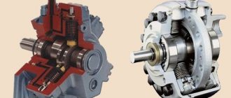
To ensure that MTZ tractor engines do not fail due to high friction of parts, Belarusians use a sophisticated lubrication system. Its key component is the oil pump, which forcibly supplies oil to the rubbing parts of the engine. The lubrication system provides lubrication to the moving elements of the crankshaft, camshaft, fuel pump gears and spaces.
The oil pump on the MTZ tractor supplies technical fluid under pressure by flushing (valves) or spraying. We’ll talk about its characteristics and structure, circuit and main components, as well as how to check, remove and replace later in the article.
Centrifuge of the MTZ 82(80) tractor: device, disassembly, maintenance and adjustment
The cleanliness of the oil in an internal combustion engine is important. The absence of foreign inclusions in the oil ensures optimal lubrication and preservation of the service life of the rubbing surfaces in the joints of the piston group parts and the crank mechanism. The lubrication system of the D-240 diesel engine and its modifications of MTZ tractors includes a centrifuge. The function of the unit is to clean the circulating oil in the engine system from contaminants, and the name itself speaks of the centrifugal principle of operation.
Detailed device D-240
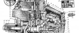
The diagram below shows the parts of the D-240 engine in a longitudinal section, where the full set of components is listed, but we have only compiled a list of these parts:
- Carter.
- Backdrop (back sheet).
- Flywheel.
- Oil filler neck.
- Coarse fuel filter.
- Air purifier.
- An exhaust manifold.
- Cylinder head.
- “Breathing” valve (aka breather).
- Electric torch heater and its tank.
- Of course, a generator.
- Thermostat.
- Water pump.
- Fan.
- Fan drive belt.
- Front support.
- Centrifugal oil filter.
- Oil measuring ruler.
- Fuel pump.
- Injector (direct fuel injection).
- Emergency (emergency) engine stop device.
- Intake manifold.
- Fine fuel filter.
- Starter.
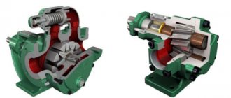
Centrifuge device
MTZ tractors with D-240, D243, D245 engines are equipped with full-flow centrifuges with a nozzleless hydraulic drive under catalog numbers 240-1404010-A , 240-1404010-A-01 , 240-1404000-A , which do not differ in design and are interchangeable .
An example of equipping with nozzle centrifuges are diesel engines SMD-62, D-65, tractors T-150, YuMZ-6, where the unit in the bottom of the rotor has jet nozzles for hydraulic drive.
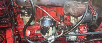
In the tractor configuration, the unit is located on the right side and is connected by its bracket body to the diesel unit. At the same time, at the place where the unit is attached to the block, a connection is provided between the oil lines in the block and the centrifuge. The centrifugal drive of the device is carried out by the pressure created by the engine oil pump.
Rotor
The unit consists of a housing and an axis of rotation with a rotor installed in it. The latter includes a frame, an inner glass, an upper and a lower lid. The top cover is secured to the frame with a nut and sealed with a rubber ring. The axial movement of the rotor on the axis is limited by a nut installed through a washer at its threaded end. The axle has an oil-conducting channel inside. The rotor is closed on top with a protective cap and tightened with a nut and washer. And also to improve the quality of cleaning, later full-flow centrifuges for diesel engines of MTZ tractors additionally installed a filter mesh on the rotor housing.
Frame
The housing is made in one piece with the mounting bracket of the unit, equipped with channels and valves:
Supply channel , fed through a pipeline from the oil pump and connected to the channels of the centrifugal hydraulic drive of the rotor.
The pressure channel passes purified oil into the diesel main line.
Drain channel - connected to the cavity of the diesel crankcase.
An unregulated safety valve is installed at the inlet of the rotor - it cuts off oil into the diesel sump when the pressure increases above 0.65-0.7 mPa (6.5-7 kgf/cm²), that is, when the resistance to the passage of lubricant through the centrifuge increases as a result of the accumulation of contaminants, the valve will operate and will open the drain into the diesel sump.
The adjustable drain valve maintains the pressure in the system within 0.2-0.3 MPa (2-3 kgf/cm²). When starting a diesel engine, cold thick oil can create a pressure of the above operating values, which can cause an emergency situation in the operation of the diesel engine (for example, in the form of squeezing out oil seals). The purpose of the drain valve is to equalize the pressure value to 2-3 atmospheres by passing part of the oil into the drain.
The non-adjustable pressure reducing valve is designed to redirect cold oil past the oil cooler when starting the diesel engine. The force of the valve spring is less than the resistance of the radiator when unheated grease passes through it. After the diesel temperature rises to the operating value of 80-95°C and the oil loses its viscosity, the resistance to passage through the radiator will drop and the pressure reducing valve will close the drain channel, directing the oil through the lubrication system radiator for cooling.
Do-it-yourself repair of MTZ-80(82). Part 2. Page 827 of 943
That is, compression (especially the lower) are also involved in oil removal
There, the topmost part is involved in oil removal, but it removes about 2-3% of the total amount of oil removed by the rings
If the bearing is for vibration, then you can weld a piece of chain and jack it up, just wrap the strip so that it doesn’t get stained with bristles from welding
I pulled it out with two screwdrivers (I smeared the axle shaft with epoxy and sand, it’s been running for five years now, under the gun)
The oil seal on the axle shaft got dirty, took off the cover, and there were small sparkles, the bearing was wearing out along the way [image] I saw how to remove the axle shaft, but is there a factory puller so that you don’t touch the axle shaft, but pull out the bearing?
Why, it’s so difficult to put the axle shaft back later. I don't see any problems.
Good afternoon Tell me how to correctly install the impeller inside the centrifuge relative to the oil discharge holes? Cold pressure 3-4, hot 1-1.5. After turning off the tractor, you can’t hear the centifuge spinning. When removing the protective cap, the centrifuge can easily be rotated by hand in any direction. If you look at the axis of rotation of the centrifuge from above, in which direction should it spin? clockwise or counterclockwise. The impeller blade should be before the hole (when viewed clockwise from above) or after.
I watched a bunch of videos on YouTube about the centrifuge at MTZ - nowhere is it shown how to CORRECTLY install a cone mesh with an impeller inserted into it. People simply put it on and close it with a clamping ring and then put on the centrifuge rotation hood.
Another question: could the reason for the centrifuge not rotating be the lack of a washer that is placed on top of the mesh and impeller. It was lost by the previous owner.
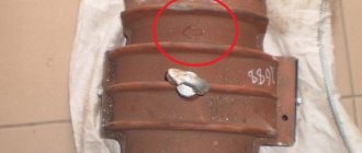
Another question: when assembling the centrifuge, it is written in the books to align the marks on the base of the centrifuge and the cap. What do these marks look like? In the video, no one ever pays attention to these marks and does not combine anything.
Another question: could the reason for the centrifuge not rotating be the lack of a washer that is placed on top of the mesh and impeller.
Probably it can. I made a cover from a Kamaz oil filter.
The oil seal on the axle shaft got dirty, took off the cover, and there were small sparkles, the bearing was wearing out along the way [image] I saw how to remove the axle shaft, but is there a factory puller so that you don’t touch the axle shaft, but pull out the bearing?
If the bearing is to be thrown out, then weld a chain or long studs to both cages and use a jack to remove the bearing through the end of the axle shaft immediately from the stocking and from the axle shaft.
Guys, tell me what kind of plow (in what cases is it used) 3-hull with an additive (or without) at MTZ.
Good afternoon to CORRECTLY place the conical mesh with the impeller inserted into it.
And not all centrifuges are too much after stopping, you need to look at the deposits
I have already studied this scheme - thank you very much. There are deposits on the walls. Maybe it’s winter now and the engine doesn’t warm up that much, although I regularly push snow on weekends and a lot. The book says that after stopping the diesel engine, you should hear the rotation of the centrifuge. I do not have it. The main question for me is how to position the impeller 24 relative to the holes in the central shaft 18. I have lost the cover 26. I watched how Anatolich69 cleans the centrifuge - it doesn’t have a conical mesh or a lid at all 26. And it seems to be spinning for a while - it’s not clear. Which direction should the centrifuge rotate?
Which direction should the centrifuge rotate?
Judging by the photo above, counterclockwise when viewed from above. make cover #26! and the upper valve can be tightened (under plug No. 8 which is in the photo).
what's the oil pressure?
The book says that after stopping the diesel engine, you should hear the rotation of the centrifuge.
I only had this happen once. Although I washed the centrifuge many times. I somehow didn’t attach any importance to it, but now I think maybe the impeller was installed incorrectly
the eyes are afraid and the hands are doing
Absolutely not a well thought out design! When installing a mesh with an impeller inside, there are no marks, grooves, or recesses that would allow you to accurately place the filter and ensure correct oil spray and rotation of the centrifuge. The mesh with impeller rotates 360 degrees. And according to science, the oil jet must accurately hit the impeller blade and only then will the centrifuge rotate and the oil purification process begin. In the T-25, at the bottom of the centrifuge there are nozzles for oil exhaust, which provide rotation, but on MTZ there is some kind of nonsense with this. It can’t be that after so many years of producing tractors with such an oil purification system, only now the question came to my mind: how should the impeller be positioned CORRECTLY? Heh
Centrifuge operation
Oil from the pump enters the unit through a channel in the housing, passes through the annular channel and holes in the axis to the nozzle secured with a screw. Through the holes of the nozzle, the lubricant is sprayed in a tangential tangential direction, acquiring a rotational movement. Next, the oil enters the cavity of the inner cup through the holes in the rotor frame and rises upward, being reflected from the collar of the frame. Centrifugal force throws contaminants towards the inner walls of the rotor. Purified oil is accelerated through tangential holes in the upper part of the frame into the internal channel of the axle. As a result, a reactive force arises that rotates the rotor. The oil, entering the channel through the holes in a purified stream, passes into the main oil line of the diesel engine.
Low pressure.
Questions can only be asked after registration.
Please login or register. What could be the reason for low pressure on a hot engine? D-240 engine, when I start it, it shows 300-350 kPa, it heats up to 80, the pressure drops to 100 kPa. on the old unit, when hot, it did not drop below 250, I changed the unit and the same problem began
There are many reasons, oil pump, liner-crankshaft gaps, tightening the drain valve on the centrifuge will not help, change the oil pump
choosing from these reasons, I already tightened the valve, changed the liners and the crankshaft 2 years ago (I didn’t have to separate the crankshaft. I’ll have to change the oil pump. But could it depend on the oily radiator?
choosing from these reasons, I already tightened the valve, changed the liners and the crankshaft 2 years ago (I didn’t have to separate the crankshaft. I’ll have to change the oil pump. But could it depend on the oily radiator?
Yes, the gaps are fine, I changed the liners. I just had an old block and the fist showed on it, I changed the block and the pressure became low
What could be the reason for low pressure on a hot engine? D-240 engine, when I start it, it shows 300-350 kPa, it heats up to 80, the pressure drops to 100 kPa. on the old unit, when hot, it did not drop below 250, I changed the unit and the same problem began
I worked on the tractor for almost 30 years, but recently I encountered a drop in pressure, I ground the crankshaft a year ago at home, a mechanic I know measured the shaft journals and said it was bored out perfectly for cold 4 and for hot 1 pressure, I ground the valves in a tsintrafuge, tightened the pressure reducing valve to the end, replaced it with a new oil pump the result did not change, changed the oil with high viscosity to cold, began to press 5 to hot 1.5. I already wanted to remove the engine but decided to check the centrifuge again, unscrewed the tube that goes to the sensor in the cabin, connected the compressor to the fitting and, under pressure, checked the tightness of the centrifuge, here it was REASON FOR LOW PRESSURE Oil was flowing from under the rotor cap in all directions, it turns out that the sealing rubber ring was worn out, I changed it to a new one and the result on a cold engine at low speeds showed 5.5, warmed up to eighty 5, adjusted the valve, now it doesn’t drop below 3. And I almost disassembled the engine, check the centrifuge and the tube on the rotor that goes into the body of the centrifuge must fit tightly. This is the exact story that happened, live and learn.
Only those who do nothing make no mistakes
Source
Node maintenance
The operation consists of disassembling and washing the rotor cavity from deposited contaminants, its inner cylindrical wall of the lid, frame, mesh and nozzle with holes.
The centrifuge is washed and cleaned of contaminants at the same time as the diesel oil is changed at each maintenance service-2 every 250 hours of tractor operation. Normal operation of the centrifuge is characterized by continued rotation of the rotor after stopping the diesel engine for 30 seconds to 1 minute. Evidence of rotation is a characteristic hum emitted by the node.
Disassembly and assembly procedure
Adjusting the Centrifuge Drain Valve
You need to understand that the main function of the valve is to relieve excess pressure when the diesel engine warms up, and the decision to make adjustments should be based on sound logic. That is, if the diesel engine’s resource is exhausted and the gaps in the main crankpins of the crankshaft and on the camshaft rotation bearings do not allow maintaining oil pressure, then there is no point in deceiving yourself and trying to increase the pressure by twisting the valve.
It is prohibited to make adjustments while the diesel engine is running!
Checking (adjusting) the fuel pump
Design and features of the VAZ 2107 gearbox: diagram, disassembly, repair
Before checking, it is necessary to ensure that the locking cone of the discharge valve is tight and that there is sufficient pressure in the pump section located in the upper cavity. Rotating the crankshaft, you need to move the regulator until the needle on the pressure gauge stops at 15 MPa. The engine is then stopped and the fuel supply is turned off using the control lever. When the pressure drops on the pressure gauge in less than 10 seconds, the valve is in good working order and can be used for further use.
To adjust the exact angle at which fuel begins to flow, you will need to screw in/unscrew a special adjusting bolt.
When unscrewing the bolt, the angle will increase, and when screwing it back in, it will decrease accordingly. Please note that one turn (turn) of screwing in/unwinding adjusts the engine speed by approximately 30-50 revolutions. When the bolt is loosened, the performance and throughput of the pump decreases proportionally, and when tightened, on the contrary, it increases
Theoretical recommendations
You can logically calculate that as the fuel supply to the engine increases, its torque also increases, which naturally increases the rated power of the D-240 engine. In addition, the speed of operation is increased to the limits of its capabilities.
Changing the oil in the UTN-5 pump is necessary only after disassembly and repair, and is not necessary for everyday use of the tractor. Filling of diesel oil should be done through the injection pump crankcase in a volume of 150-200 ml.
Oil filter to replace a centrifuge
In addition, it should be noted that the engines of MTZ tractors, especially the latest versions, are equipped instead of a centrifuge with a full-flow oil filter with a replaceable, non-separable cartridge. The filter is absolutely interchangeable and, if desired, can be installed in the same place instead of the centrifuge. The filter housing is also equipped with an adjustable drain valve, which is adjusted in the same manner.
The advantage of the filter is its simplicity of design and ease of maintenance. Despite the assertion of experts that a centrifuge works more efficiently in oil purification, we can affirmatively say that taking into account the use of modern brands of motor oils and high-quality replaceable filter elements, installing a filter instead of a centrifuge will simplify tractor maintenance and will not affect the service life of the diesel engine.
Source
Engine D-245
In order to ensure a better level of acceleration, a turbine compressor is used with the ability to adjust the air flow. This ensures an increased level of torque even at a minimum number of crankshaft revolutions. At the same time, such an engine with a turbine exhausts exhaust gases that comply with European standards Euro 3. But the entire series of such engines is intended for use only in ambient temperatures ranging from -45 to +45 degrees. The main place of use of these units is their installation in road, construction, and wheeled equipment.
Adjusting the cylinder head tightening
The order of tightening the cylinder head bolts determines the sequence and force with which the flywheel bolts are tightened in the threaded connections
It is important to remember that the cylinder head tightening torque should be in the range of 190-210 Nm. In this case, the stud nuts and bolts must be tightened to capacity.
The adjustment process is performed as follows:
- First you need to turn the crankshaft using the main bearings and connecting rods until the valves of the first cylinder close. At this moment, the intake in the first cylinder is just opening, but the exhaust is closing. After this, the gaps in valves 4, 6, 7 and 8 are adjusted (counting is carried out from the fan side).
- After this, the crankshaft is turned 1 revolution so that the 4th cylinder is blocked. At this moment, adjustments are made to valves 1, 2, 3, and 5.
Upon completion of this process, according to the indicated scheme, it is necessary to return the rocker arm axis to its original position, and then adjust the clearances of the D-245 valves present between them and the rocker arms.
Valve adjustment D-245
Separately, it is worth considering the procedure for adjusting the D-245 valves. Before starting this process, it is recommended to study the features of this node. So, the camshaft has 5 supports at once, and is driven by the crankshaft, as well as by the distribution gear. Special 5 bushings are used in the form of bearings installed by pressing. At the same time, the front one is made of aluminum and is located in the fan area and is equipped with a thrust collar, which is responsible for fixing the camshaft and preventing its axial shifts. All other bushings are made of cast iron.
In order to correctly adjust the valves, it is necessary to take into account that a steel rod is used to create pusher rods. It has a spherical part that fits directly into the pusher
The adjustment process itself occurs as follows:
First you need to unscrew all the nuts that secure the axle stands, after which they themselves, along with the springs and rocker arms, must be removed. Next, the head mount is unscrewed and then dismantled. The valves themselves become dry when the springs, washers, various seals, and plates are removed. Now the valves are being ground in using special machines or stands. To do this, first apply lapping paste to the chamfer of the spare parts and additionally add stearic acid. The process of adjusting the valves (aka lapping) is carried out until a solid matte edging appears. In this case, its width should be at least 0.015 cm
It is important to prevent the bands from breaking, and any deviations in width are allowed within 0.5 mm.
Read more: Replacing the 2008 Toyota Corolla alternator belt After completing the adjustment, wash the cylinder head and the valves themselves. Next, the working elements are lubricated with oil for the power plant. The grinding process can be carried out manually using conventional metalworking tools. But in this case, the time and labor costs for this operation will increase significantly.
The D-245 engine is a diesel power plant, often used in various construction, road or other similar equipment.
If you find an error, please select a piece of text and press Ctrl+Enter.
Tractor MTZ-82
Everything about the MTZ-82 tractor: design, operation, repair, technical characteristics and repair. Engine D-240: MTZ engine repair.
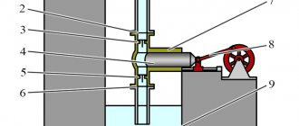
The D-240 engine has a combined lubrication system. Based on the operating conditions of the parts, oil flows to the rubbing surfaces (crankshaft crankpins and main journals, camshaft bearing journals, fuel pump gear bushings and intermediate gear) under pressure, but in a pulsating flow (valve mechanism) or by splashing. The engine lubrication system includes: a full-flow centrifugal oil filter (centrifuge), an oil pump with an oil receiver and an oil cooler. The lubrication system also includes connecting fittings, oil lines, safety valves, control devices and others. Some diesel components (starter, pump, fuel pump) have their own autonomous lubrication circuit. To lubricate the engine of the MTZ-82 tractor, motor oil is used: in winter - grade M8G2, in summer - M10G2. The oil must be changed every 480 hours of engine operation.
Lubrication system diagram: 1 - oil cooler; 2 - main oil line; 3 — oil pressure indicator; 4 - mesh; 5 - centrifuge; 6 - oil pump; 7 - pressure reducing valve; 8 - drain valve; 9 - safety valve; 10 — thrust rings; 11 - pipe; 12 — oil receiver; 13 - oil cooler.
Oil pump D-240
Single-stage, gear type, mounted on the first crankshaft main bearing cap and rotated from the engine crankshaft. The pump consists of a cover, a housing, drive and drive gears mounted on the shaft, as well as a driven gear located on the pin.
During the rotation of the gears, a vacuum is formed in the suction area, which facilitates the flow of oil into the oil intake of the pump. Getting into the gear teeth, the oil is supplied to the main line, and from there it goes to the rubbing units.
The depth of the borings for the gears in the housing, their width and placement are carried out with high precision. To create a tightness in the internal cavity of the oil pump, the mating planes of the cover and housing are carefully ground. It is not allowed to move the cover from one pump to another. The oil supply by the pump is 36 liters per minute at a speed of 2320 rpm and the generated pressure is 0.70-0.75 MPa (7.0-7.5 kgf/cm²).
Oil pump: 1 - oil intake; 2 - pump housing; 3 — driven gear pin; 4 — driven gear; 5 — housing cover; 6 — pump drive gear; 7 - pin; 8 — pump shaft; 9 - drive gear; 10 - pipe.
Oil filter
The D-240 engine centrifuge is designed to clean circulating oil in the lubrication system. A centrifugal filter equipped with a nozzleless hydraulic drive is installed on the engine.
The filter housing has an axis on which the rotor rotates. The cover is attached to the frame with a nut and sealed with a rubber ring. The rotor is held from axial movement by a washer and nut located at the upper end of the threaded axle. The rotor is closed from above with a cap secured with a nut and washer. An oil drain tube is located in the internal cavity of the axle. Under the influence of centrifugal forces, small particles, wear products of parts and oil decomposition remain on the inner walls of the rotor. The purified oil is thrown at high speed through a tangential hole into the internal bore of the rotor housing in the area of the inlet holes of the rotor axis. As a result, a reactive force is generated that rotates the rotor. Next, the oil is fed through the holes in the rotor axis and the tube into the main oil line.
The safety valve controls the pressure in front of the rotor to 0.65-0.70 MPa (6.5-7.0 kgf/cm²). If the oil pressure at the rotor inlet exceeds this value, it is drained through the valve into the sump.
Engine oil pump malfunctions
Failure of the oil pump leads to disruption of the circulation of engine oil and reduces the cooling efficiency of the engine. Ignoring the problem can cause significant damage to the engine and lead to more expensive repairs.
Most often, gear NSs experience the following malfunctions:
- The pressure decreases.
You need to check the oil pump as soon as the indicator light on the dashboard comes on.
- Blood pressure rises.
Increasing oil pressure in the cooling system is also a problem. If it is slightly exceeded, oil seeps through seals, pipe connections, seals, etc. This is unpleasant, but not critical.
If the operating pressure is significantly exceeded, the bypass valves will prevent the flow of fluid into the cooling system, and the engine simply will not start.
- Oil consumption increases.
If you notice a significant increase in oil consumption, you need to check the engine oil pump. If it leaks into the cylinder cavity, the exhaust will change color.
The causes of malfunctions are the following defects:
- Clogged oil receiver mesh.
The mesh is necessary to filter the fluid at the inlet of the oil pump. It becomes clogged, as a result of which the pressure in the system decreases or the supply of technical fluid stops. The mesh becomes more clogged when using mining or after washing the power plant.
- Wear of the inner surface of the housing (mirror).
Wear of the housing usually occurs when the service life of the pump is exceeded. In this case, the entire unit is changed, and sometimes along with the crankshaft gear.
- Gear wear.
Oil pump gears are subject to accelerated wear when using the wrong oil, running out, or rarely changing the fluid when it thickens.
- Low oil level in the engine crankcase.
If the oil level is insufficient, the pump works at its limit, overheats and may break. You need to monitor the fluid level and add it as needed.
Adjusting the drain valve of the MTZ 82 centrifuge
When changing oil in a diesel crankcase, follow the following recommendations:
To drain the oil, there is a hole in the lower part of the diesel oil sump that is closed with a plug.
CHECKING AND ADJUSTING CLEARANCES IN DIESEL VALVES
Check and adjust the gaps between the valves and rocker arms after running in a new tractor and every 500 hours (with maintenance-2), as well as after removing the cylinder head, TIGHTENING the cylinder head bolts and when valve knocking occurs. On a cold diesel engine, adjust the gap between the rocker arm striker and the end of the valve stem to 0.25. 0.30 mm for intake and exhaust valves.
Make adjustments in the following order (Fig. 35):
Rice. 35. Adjusting clearances in diesel valves
It is possible to adjust the valves in another way:
After adjusting the gaps, replace the cover cap. When rechecking on a cold diesel engine, clearances of 0.20 are allowed. 0.35 mm for intake and exhaust valves.
CHECKING THE TIGHTENING OF THE CYLINDER HEAD BOLTS
Check the tightness of the cylinder head mounting bolts after running in a new tractor and after 1000 hours (with maintenance-3) on a warm diesel engine in the following order:
DISASSEMBLY AND CLEANING THE CENTRIFUGAL OIL FILTER ROTOR
Clean the centrifugal oil filter rotor simultaneously with changing the oil in the diesel crankcase.
Clean the rotor in the following sequence:
a) unscrew cap nut 1 (Fig. 37) securing cap 2 of the centrifugal filter and remove it;
b) insert a screwdriver (small diameter rod) between the filter housing and the bottom of the rotor and stop the rotor from turning (see Fig. 38). Using a wrench S=36 mm, rotating the nut 4 securing the rotor shell, pull the shell 3 off the rotor body;
c) using a wooden scraper, remove the layer of deposits from the inner walls of the rotor bowl;
d) if necessary, clean the nozzle holes in the upper part of the rotor column;
e) assemble the rotor in the reverse order of disassembly, aligning the marks on the rotor and the rotor cup. Before installing the rotor shell, lubricate the O-ring with engine oil. Screw the cup fastening nut with a little force until the cup is completely seated on the rotor; Tighten nut 1 for securing the cap 2 to a torque of 3.5-5.0 kgf*m (35-50 N*m);
e) check the operation of the centrifugal oil filter.
Characteristics
K126 carburetor structure, adjustment and repair
Before studying the valve adjustment on the D-245 engine, let’s consider its technical parameters:
- Manufacturer: MMZ (Minsk).
- Type - four-stroke in-line diesel engine with an in-line arrangement of 4 cylinders.
- The fuel mixture is supplied by direct injection.
- Compression – 15.1.
- Piston displacement – 125 mm.
- The cylinder diameter is 110 mm.
- Working volume – 4.75 l.
- Cooling is a liquid system.
- Speed – 2200 rotations per minute.
- Average fuel consumption is 236 g/kWh.
- Power indicator – 77 kW.
- Camshaft gear.
- Intermediate gear.
- Crankshaft toothed element.
- TN drive wheel.