How to launch a railway in the Urals
The pre-heater for the Ural-4320 vehicle is basically similar to the pre-heater for the KamAZ-5320 and KamAZ-4310 vehicles.
Its design features include a slightly different arrangement of units caused by layout considerations, and a special control panel installed under the hood of the car on the left side of the radiator. Instead of one lever for switching operating modes of the heater, located in the driver's cabin of the KamAZ-5320 and KamAZ-4310 vehicles, the control panel for the heater of the Ural-4320 vehicle contains switches for the electromagnetic fuel valve, pump unit, transistor switch with a spark plug and electric fuel heater.
When using low-freezing liquid in the cooling system, warming up and starting the engine are carried out in the following sequence. The valve on the fuel tank of the heater is opened, and by turning on the pump unit with a switch, a centrifugal fan blows through the boiler flue for 10...15 s. Then, by turning on the electric heating with a switch (non-fixed activation), the fuel is heated for 30...90 s before it is injected into the mixture formation zone of the burner. The holding time of switch 5 in the on position depends on the ambient temperature and is: 30 s at minus 30 °C; 60 s at minus 40 °C; 90 s at minus 50 °C.
Promotional offers based on your interests:
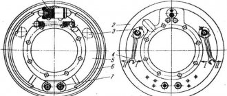
Rice. 2.35. Control panel for the heater of the Ural-4320 car: 1 - switch for the electromagnetic fuel switch. panel: 2 - pump unit switch; 3 - transistor switch switch with spark plug: 4.6 - plates; 5 — switch for electric heating of fuel
After this, the switch (non-fixed switching) turns on the transistor switch with a spark plug, the switch turns on the pumping unit, and the switch turns on the electromagnetic fuel valve. The switch handle of the transistor switch with a spark plug is held in the on position for no more than 30 seconds until a characteristic hum appears in the boiler, indicating ignition of the fuel in the burner. A working heater starts up within 10… 15 s. After releasing the switch handle of the transistor switch with a spark plug, a continuous, even hum should continue in the heater boiler, indicating that the heater has reached stable operation.
If the start of the heater fails, the electromagnetic fuel valve and the pump unit are turned off and after a minute the test run of the heater is repeated in the specified sequence.
When the liquid in the cooling system is heated to a temperature of 40 °C, the engine is started and then warmed up to a temperature of 70...80 °C. During stable engine operation, the heater is turned off by stopping the fuel supply to the heater burner by the electromagnetic fuel valve, and the heater boiler flues are purged with a centrifugal fan for 20...30 s.
If water is used in the cooling system, the engine is warmed up and started in the following sequence. The heater is started for 10...15 s without water in the cooling system. Then water in a volume of 16 liters is poured through the neck into the heater cylinder, keeping the radiator cap open. The engine warms up until abundant steam is released from the radiator filler neck, after which water is added until the cooling system is filled. And finally, the engine starts, warms up to a temperature of 70...80 °C, and the heater turns off.
ANSWERS to UA
Ticket number 1.
The procedure for starting the pre-heater of the YaMZ-236 (238) engine.
The PZD-30 starting heater is used for pre-heating of diesel engines of KamAZ and Ural vehicles at an air temperature of 10 degrees and below. The heater is controlled from a remote control located in the cab on the right, next to the right door.
To start PZD-30 you need:
— check the level of coolant (antifreeze or antifreeze) in the engine expansion tank
- turn on the "mass" switch
— open the tap on the fuel tank of the heater
- turn on the right switch on the remote control (solenoid shut-off valve switch)
— turn on the bottom switch on the remote control (fuel electric heating switch) for 20–40 seconds, while the boiler is purged and the diesel fuel is heated
- turn on the upper left switch (spark plug switch), - the fuel mixture is ignited and burned, ensuring heating of the liquid in the boiler,
- when the fuel in the boiler pops, turn off the spark plug switch and the fuel heating switch
The circulation of hot liquid from the boiler to the engine and back, as well as the supply of air to the boiler, is carried out using a liquid pump and a fan of the pump unit.
When the coolant temperature in the engine reaches about + 30 degrees and above, you should:
- turn off the right switch (solenoid valve) - in this case, the boiler is purged for about a minute
— close the shut-off valve on the fuel tank
The amount of fuel supplied to the boiler is adjusted to prevent the appearance of an open flame from the exhaust pipe of the boiler, using the adjusting screw on the fuel pump of the pumping unit.
IT IS STRICTLY PROHIBITED to use the heater in enclosed spaces.
2. The sequence of carrying out a control inspection of the Ural-4320 vehicle before leaving the vehicle depot.
The purpose of the inspection is to check the technical condition of the vehicle and its readiness to perform the task.
Inspection sequence:
— inspect the vehicle from the outside, from the left front wheel, then clockwise: cabin, tail, body, transmission, chassis
- check :
— integrity of headlight glasses, lanterns, wipe cockpit glass, mirrors, lighting devices, license plates
— complete set of tools, presence of a first aid kit, 2 wheel chocks, fire extinguisher
— amount of fuel in tanks, level and quality of oil in the engine crankcase, coolant level in the radiator expansion tank
- the amount of compressed air pressure in the pneumatic system
- open tire valves
— Start the engine and:
- warm up the engine (at a temperature of 10 degrees and below - using a pre-heater)
— check for leaks from the cooling, lubrication, and power steering systems
— check for compressed air leakage from the system
- listen to the engine in all operating modes
-check the operation of control devices
— check the operation of the headlights, tail lights, direction indicators, horn, windshield wipers and windshield washers
- check the operation of the generator
— Stop the engine and check:
— audible operation of the centrifugal oil purification filter, as well as the absence of leaks from the systems
- Also check:
— condition and fastening of steering rods, cotter pins of rod nuts
— reliable tightening of wheel nuts
— free moves: steering wheel, brake pedals, clutch
— reliability of fastening of the spare wheel
— serviceability of the side locks of the body, as well as:
— you need to make sure that the winch cable is tightly wound on the drum, the power take-off lever is in
neutral position and securely fastened
— When starting to move, check:
— serviceability and reliability of the service brake system and parking brake
- clutch operation
— ease of control of the transfer case and gearbox
— ease of rotation of the steering wheel (without the appearance of sudden efforts when turning the steering wheel)
3. Lower, remove from the holder and install the spare wheel of the KamAZ-4310 vehicle in its original position.
The spare wheel is installed in a holder behind the cab. Raising and lowering the spare wheel is carried out using
hydraulic pump and hydraulic power cylinder, as well as the pump allows lifting and lowering the cabin.
To lower the wheel you must:
- loosen the nuts of the clamping screws of the holder
— move the hydraulic pump control levers to the “Wheel lowering” position
- insert the mounting blade into the hole in the pump handle and swing the blade handle up and down to lower the wheel
To lift the wheel:
— move the pump levers to the “Wheel lift” position
- roll the wheel into the lowered holder, and, pumping the handle of the paddle, raise the wheel to the upper position
- secure the wheel with the nuts of the coupling screws
Ticket number 2.
1. Reasons causing ineffective braking or lack of braking
car Ural - 4320 with the service brake, with the brake pedal fully pressed.
The service brake system of a Ural vehicle differs from the brake system of a KamAZ vehicle in the presence of a pneumohydraulic drive (pneumohydraulic brake booster). The pneumatic drive is the command (control) part, and the hydraulic drive is the executive (working) part of the pneumatic booster with the main hydraulic brake cylinder installed on the wheel brake mechanisms of the wheels. By car
Ural 4320 uses 2 circuits: the first hydraulic circuit operates the brakes of the front and middle axles, the second - the brakes of the rear axle, each circuit uses its own amplifier.
Reasons causing ineffective / weak / braking:
— insufficient air pressure in the brake system
— oiling of the brake pads of the wheel brake mechanisms due to clogging of the axle breathers
— leakage of brake fluid from hydraulic cylinder drives
— presence of air in one of the circuits
- different clearance between brake pads and brake drums on some wheels
— different wear of brake pads on wheels
Reasons for lack of vehicle braking:
— lack of compressed air in the brake system
— lack of brake fluid in the hydraulic circuits
2. Sequence of disassembly and maintenance of the filter - sedimentation tank for coarse fuel purification of the KamAZ-740 engine. Removing air from the power system.
With daily T.O. (E.T.O) it is necessary to drain the fuel sludge from the coarse filter and fine fuel filters, followed by removing air from the fuel system.
Disassembly, washing of the filter-sump, replacement of paper fine fuel filters is carried out during work according to T.O.-2. To drain fuel from the filters, remove the lower drain plugs on the filter housings. It is PROHIBITED to dump fuel on the ground!
To disassemble the filter-sump, unscrew the four upper bolts on the top filter cover, then remove and wash the metal mesh umbrella filter and the cavity of the filter bowl with gasoline or diesel fuel and blow with compressed air.
When subsequently assembling the filter, check the integrity of the rubber sealing ring of the filter bowl.
After that, remove air from the fine fuel filters:
- raise and secure the cab with a safety stop
— loosen the bleeder bolt (unscrew it halfway or one turn), DO NOT UNCROSS it!!!
- using a manual fuel pump located on the fuel injection pump, bleed the system until fuel appears from under the bleeder bolt
- tighten the bolt
- lower the cabin.
3. The procedure for filling the engine cooling system of the Ural - 4320 vehicle and draining the liquid from the system.
The cooling system of the Ural - 4320 vehicle uses low-freezing liquid Tosol A - 40 or Tosol A - 65. The liquid is filled with the cabin raised, the cockpit heater (stove) valve open into the radiator filler neck, to the upper level of the edges of the radiator tubes (on a /m KamAZ - 4310 filling is carried out into the neck of the expansion tank, level control is done using a control valve on the expansion tank). After starting the engine, after 3-4 minutes, the air pockets are removed from the cooling system (i.e., the fluid should be added to the normal level).
Drain the liquid - through 4 drain valves and an open radiator cap / on KamAZ - expansion tank cap /: drain valve on the heater boiler, drain valve on the heater pump unit, drain valve of the lower radiator pipe and drain valve of the cabin heater. System capacity – 32 liters. Antifreeze is replaced after 2 years of vehicle operation.
Ticket number 3.
1. Operations to remove condensate from the pneumatic drive of the brakes and the air pressure regulation system in the tires of the Ural - 4320, / KamAZ -4310 vehicles, during daily maintenance / E.T.O. /.
Condensation is removed from the system in order to prevent water from entering the air ducts, brake valve, and wheel brake chambers.
Before draining the condensate, check and bring it to normal / 6.5 - 7.2 atm. / compressed air pressure in the brake system.
To drain the condensate, you need to press or pull to the side the shut-off valves on ALL receivers of the system, this will release water along with compressed air, after which the air pressure in the system should be brought to normal.
2. Checking the level, methods for determining the quality of motor oil in the crankcase of Ural - 4320, KamAZ -4310 engines, when carrying out KO. List the brands of oils.
Oil quality is checked in 4 ways:
— visually, the oil should be transparent, — the oil level marks on the dipstick should be visible through the oil film
— to the touch, when wiping the oil from the dipstick between your fingers, the presence of foreign particles should not be felt
- smell, - the oil should not smell like fuel
— “oil stain” method — when applying a drop of oil from the dipstick onto a sheet of clean paper, an oil stain is formed. If dirt appears in the center of the oil stain, the oil should be replaced.
Motor oil brands:
— engine oil: for summer operation — M 10 G2 K
— in winter — M 8 G2 K
— all-season – D V — A S W- p 10 V
3. List the features of switching on oil radiators for YaMZ-236 (238) and KamAZ-740 engines.
The oil cooler is turned off to prevent engine overcooling at air temperature
0 degrees and below.
The oil radiator of the YaMZ engine is turned off by a valve located on the lower radiator pipe.
The oil cooler on the KamAZ engine is turned off by a tap located on the housing of the full-flow centrifugal filter.
Brands of motor oils: summer oil - M10G2K, winter oil - M8G2K; all-season – DV –ASZp – 10V.
Lubrication system capacity: YaMZ -236 (238) - 23.7 liters, KamAZ - 740 - 26 liters.
Oil change: at TO-2 or during Seasonal Maintenance.
Ticket number 4.
1. List the reasons that prevent the KamAZ-4310 engine from starting during winter operation, at low temperatures.
To operate a diesel engine, the following grades of diesel fuel are used: “DL” – summer diesel, at air temperatures above 0 degrees, “DZ” – winter diesel, at temperatures from 0 to – 30 degrees, “DA” – arctic diesel, at temperatures below - 30 degrees.
At low temperatures, the summer fuel remaining in the fuel tanks thickens, i.e. – paraffin films form in the diesel fuel – waxing of the fuel occurs, as a result of which the plunger pairs of the high-pressure pump
(Fuel injection pump), injector nozzles, become clogged with these films of paraffin. To prevent this, it is necessary when conducting seasonal maintenance. replace fuel according to the season. In the case when in winter there is thickened summer fuel in the fuel tanks, to stop paraffinization - to dissolve paraffin films, you can add kerosene to the fuel tanks: - for 170 liters of tank, you should add 5 - 7 liters of kerosene, but after that you will experience black smoke when the engine is running. The following reasons for preventing the engine from starting are: - freezing of water on the mesh fuel intake in the tank, in the filter-sump, in the fuel lines; - difficult movement of the fuel pump rack / injection pump / due to thickening of the lubricant in the pump.
2.Checking the condition, the amount of deflection (tension) of the drive belts of the liquid pump, generator, power steering pump, YaMZ engine - 236 (238). Procedure for replacing belts.
A feature of the drive on the YaMZ engine is the presence of 2 drive belts: the first belt is the generator and water pump drive belt from the fan drive fluid coupling pulley, the second belt is the fluid coupling pulley drive belt from the crankshaft pulley. (The KamAZ-740 engine uses one common drive belt, paired from two narrow belts).
Checking the condition of the belts: - the belts should not have cuts, peeling, or be oily.
Checking the belt tension: - checking is carried out by pressing on the middle of the belt (between the drive pulleys), with a force of 4 kgf, from the water pump, and the belt deflection should be 15 - 22 mm. It is not recommended to use the extreme adjustment points: 15 and 22; on average, the deflection should be about 19 mm.
The tension of the drive belts is carried out by moving the generator up and down, with the generator stop bolt loosened and when the tension roller moves, also with the lock bolt loosened.
3. The procedure for checking the value and adjusting the free play of the clutch pedal of a vehicle
Ural - 4320.
The clutch drive of the Ural vehicle - 4320 is mechanical (on the KamAZ 4310 vehicle, a pneumohydraulic booster is used in the drive).
Adjusting the free travel of the clutch pedal on the Ural - 4320 is carried out by changing the length of the adjusting rod located between the clutch control drive lever and the clutch release fork shaft lever. To increase the free travel of the pedal, the tip - the adjusting fork is rolled off the rod, to reduce the travel - screwed on, after which the lock nut is tightened. The amount of free play is checked using a ruler and the pedal travel should be within 30 - 40 mm. With correctly adjusted free travel of the clutch pedal, the full travel of the clutch release lever will be 39.6 - 45.8 mm, and its free travel will be 6.1 - 9.2 mm.
Ticket number 5.
1. The procedure for checking the oil level in the power steering pump reservoir. Differences in checking the oil level of engines YaMZ - 236 (238), KamAZ - 4310. Name the brands of oils.
Check the oil level in the pump reservoir for:
- YaMZ engine by the internal mark on the pump body, after removing the strainer tank from the filler neck,
- KamAZ engine - the level in the pump reservoir is checked using a dipstick attached to the cover of the pump reservoir. On the dipstick there are marks for the minimum and maximum oil levels in the tank.
Brands of oils used: - "R" brand oil (steering oil), substitute: - "AU" brand oil (spindle oil). Oil change after 2 years of operation..
A method for checking the operating modes of the fluid coupling of the KamAZ-4310 engine fan drive during a vehicle inspection.
The hydraulic coupling mode switch has 3 positions:
— “O” position — the fan is turned off, this position is used for fording
— position “B” — all-mode, i.e. automatic operating mode: - the engine is hot - the fan is running, the engine is cold - the fan is not running
— “P” position — the fan runs constantly, even when the engine is cold. This mode is used in hot weather, but CONTINUOUS operation of the fluid coupling in this mode should not exceed 4 hours
To check the operation of the fluid coupling, you should warm up the engine to operating temperature according to the device: + 85 - + 95 degrees. Switch the switch to the “O” position, while the fan impeller should not rotate, then switch the switch to the “B” position - the fan impeller should automatically turn on and off, then move the switch to the “P” position, while the impeller should rotate for a long time, with the coolant temperature readings even below + 80 degrees.
Checking the correct connection of 6 ST – 190 batteries to the on-board network of the Ural - 4320 vehicle.
The on-board voltage of the Ural car is 4320: 24 volts. To obtain a voltage of 24 volts, two batteries are used in series; the positive terminal of the first battery should be connected to the negative terminal of the second battery with a power wire with pole pieces, having previously cleaned the battery terminals with sandpaper.
The positive terminal of the connected batteries is connected to the main power terminal of the starter traction relay, and the negative terminal is connected to the battery switch, and through it to the body / “ground” / of the vehicle.
To reduce oxidation of the terminals, it is recommended to lubricate them with a thin layer of LITOL-24 lubricant.
Checking the correct connection of batteries to the vehicle's on-board network:
To these terminals: POSITIVE and MINUS you need:
— put on, without fastening, the wire ends of the power wires of the vehicle’s on-board network
— turn on the headlights, and check in which sector of the ammeter / + or - / the arrow will deviate. If the wires are correctly connected to the battery terminals, the ammeter needle should deviate to the “MINUS” sector, i.e., the batteries will be discharged, if the arrow deviates to the “PLUS” sector, i.e. in battery charging mode, you need to swap the connections of the car wires to the battery terminals.
Ticket number 6.
1. List the types and frequency of technical maintenance / T.O. / Ural 4320 and KamAZ -4310 vehicles.
There are 5 main types of Technical Services (TS):
— K.O. – control inspection of the vehicle before leaving the car park. Carried out to check the technical serviceability of the vehicle and the readiness of the vehicle to complete the task
- E.T.O. — daily maintenance, performed by the driver every day upon returning to the fleet. Carried out to eliminate detected vehicle malfunctions detected on the way and prepare the vehicle for the next working day
- THAT. - 1 - carried out every 1300 - 1600 km, in order to maintain the vehicle in good technical condition, prevent failures of various vehicle components and check the adjustments of vehicle units
- THAT. — 2 — is carried out after the vehicle has driven 7200 - 12000 km, in order to reduce the wear rate of the vehicle’s units and components: inspection, fastening, adjustment, and lubrication work is carried out. The difference in mileage is due to the operating conditions of the vehicle: off-road driving or on a good highway
— S.O. — seasonal vehicle maintenance. It is carried out twice a year: in spring and autumn, in order to prepare the vehicle for summer or winter operating conditions. Seasonal maintenance work is combined with work during maintenance. - 2.
2. Method for determining the degree of contamination of the engine oil pre-filter
YaMZ - 236 (238). Sequence of work to clean the filter.
The design of the full-flow centrifugal coarse oil filter is similar to the design of the filter on the KamAZ-4310 vehicle; the filter is located in the front right side of the engine. When oil is supplied under a pressure of 6 - 6.5 atm, created by the oil pump, a torque arises due to jets ejected at an angle of oil from the nozzles of the base of the filter rotor, as a result of which the rotor rotates at a frequency of about 5000 revolutions per hour. minute. At the same time, a centrifugal force is created, which throws dirt particles towards the inner walls of the rotor cap,
Because of this, the total weight of the rotor increases.
Method for determining filter rotor contamination:
.After turning off the engine, the driver hears the characteristic buzz of a rotating rotor. By the time of this sound, one can judge the degree of contamination of the rotor. If the sound time is from 1 minute to 2 minutes, the filter is clean, more than 3 to 4 minutes, the filter rotor must be cleaned.
To disassemble the filter, 20 - 30 minutes after stopping the engine (the time required to drain the oil from the filter rotor), you need to: unscrew the upper nut of the filter casing by pressing on the filter rotor and holding the rotor (in this case, the rotor is fixed in a stationary state with a stopper rotor), unscrew the upper rotor nut, remove the filter rotor cap from the axis, holding the rotor bottom with your hand, and remove adhering dirt from the inner surface of the cap, wash the surfaces of the cap and the rotor bottom in gasoline or diesel fuel, clean the holes of the rotor nozzles, check the condition of the rubber seals rings of the bottom of the filter rotor, assemble the filter in the reverse order, aligning the marks on the bottom of the rotor and the rotor cap. Assembling the filter rotor without aligning the marks is unacceptable! / because the rotor base and cap are balanced /. Tighten the rotor cap nut with a force of 8 - 9 kgf/m, check the rotation of the rotor on the axis - the rotation of the rotor should be without jamming or wobbling. When installing the outer rotor cap, carefully check the condition of the rubber sealing ring and the correct installation of the cap to prevent leaks from under the filter cap.
3. The purpose of turning off the spring energy accumulator of the KamAZ - 4310 vehicle mechanically.
Spring energy accumulators are located on the middle and rear axles of the KamAZ -4310 vehicle; they are part of the parking and emergency braking systems. In the event of an emergency drop in air pressure in the brake system, spring energy accumulators are automatically activated, keeping the vehicle stationary.
To mechanically release the energy accumulators, you should use a ring wrench “22”, turning the bolts of all four energy accumulators up to the stop, at the same time, the springs of the energy accumulators are compressed and the brake mechanisms of the wheels of the middle and rear drive axles are released.
This method of releasing the brakes is used when there is a need for urgent evacuation and towing of a faulty, damaged vehicle.
Ticket number 7.
1. Methods for adjusting the timing of fuel injection into the high-pressure fuel pump, when working on the fuel injection pump - 1.
The moment of fuel injection into the engine cylinders should be 18 degrees before TDC in the first cylinder.
To check and adjust the fuel injection timing you need to:
- remove the lower hatch on the clutch housing
- raise and secure the cabin with a stopper
- lower the flywheel lock to the lower position
aplik.ru
Preheater operation
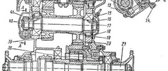
The coolant from the lower radiator manifold is supplied by the water pump of the pumping unit through pipe I (Fig. 2.7) to pipe II and enters the boiler through pipe IV.
In the boiler, the liquid, entering through the outer jacket into the inner one, forms two flows that wash the combustion chamber and the return flue.
Air is supplied to the burner by an air blower through pipe V.
The fuel pump of the pumping unit supplies fuel from the tank to the solenoid valve. When the valve is closed, before starting the heater, a portion of the fuel is heated by an electric heater. When the valve is open, fuel enters the burner through the nozzle under pressure, where it is mixed with the forced air.
The electric spark ignition system ensures ignition of the fuel-air mixture during the start-up period. Then the candle turns off and combustion is maintained automatically. The heat obtained from fuel combustion heats the coolant passing through the boiler in two streams. Through pipe 16 of the boiler, hot liquid enters the jacket of the engine cylinder block. Exhaust gases are discharged from the boiler through pipe III.