Section 2. CONTROLS AND OPERATION OF THE PAZ-32053 BUS
CONTROLS AND CONTROL INSTRUMENTS OF PAZ-32053 BUS
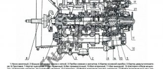
The location of the controls is shown in (Fig. 2-1 a). To the right of the driver's seat are the gearbox control lever and the parking brake handle. The gear shift diagram is shown on plate 10 of the instrument panel and fig. 2-1 b.
Rice. 2-1 Controls: a - driver’s workplace; b - gear shift diagram. 1-end of the door locking rod; 2- bag; 3-door opening handle; 4-handle for driver's landing; 5- switch for headlights, direction indicators and sound signal; 6- instrument and starter switch; 7- switch for windshield wiper, windshield washer and sound signal; 8- instrument panel; 9-window defroster; 10 - plate with gear shift diagram; 11- radiator shutter control circuit; 12- fuse block; 13-gearbox lever; 14- engine hood; 15- hood fastener; 16- hood handle; 17- handbrake handle; 18- fuel supply control pedal; 19- brake pedal; 20- cabin ventilation damper; 21-clutch pedal; 22-socket
Rice. 2-2 Diagram of the position of the instrument switch and starter key
Instrument and starter switch 7 (Fig. 2-1) is located on the steering column. In Figure 2-2. The diagram of the position of the instrument switch and starter key is shown:
“III” - in this position the key is inserted and removed from the switch. Regardless of whether the key is inserted or not, the steering shaft is locked with an anti-theft device, but you can turn on the hazard lights, door drive, portable lamp, turn on or off the batteries;
“0” - in this position the anti-theft device is disabled. To turn off the anti-theft device, you need to insert the key into the switch (position “III”) and, slightly shaking the steering wheel left and right, turn the key to position “0”.
“I” - in this position, control and measuring instruments operate and the switching on of electricity consumers is possible.
“II” - in this non-fixed position the starter is turned on.
To turn off the devices, turn the key from position I to the fixed position 0.
To avoid failure of the contact part of the instrument switch, do not leave the key in an intermediate position.
Switch for headlights, direction indicators and horn. The switch lever has six fixed positions (Fig. 2-3) - I, II, III, IV, V, VI and four non-fixed positions “A”.
If the switch lever is in position I and the central light switch button is in position II, then the low beam headlights are on. By moving the lever to position II (down), the high beam headlights are on and
blue warning light on the instrument panel. When the switch lever is repeatedly moved from position I up along the steering column (non-fixed position), the high beam headlights are signaled.
When you press the lever button (from any position) along the axis, a sound signal is activated (without locking).
When the lever is moved from positions I or II to position IV or VI (right turn) or down to position III or V (left turn), the direction indicators turn on and a green flashing warning light comes on on the instrument panel. To briefly turn on the direction indicators, the switch lever must be moved to the appropriate position “A”. When released, the lever returns to position I or II.
After completing the turn, the switch lever returns to position I or II automatically when the steering wheel is turned.
Switch for windshield wiper, washer and horn.
At lever position (Fig. 2-4):
0 — windshield wiper off;
1 — low speed windshield wiper is on;
II — high speed windshield wiper is on;
III - intermittent operation of the windshield wiper is turned on. To briefly turn on the washer and wiper, the switch lever must be moved from position 0 towards you (in the direction of the arrow).
By pressing the button of the switch lever along its axis (non-fixed position), the sound signal is turned on.
The washer can be turned on from all positions of the lever. The windshield wiper only works when the ignition is on.
The arrangement of instruments on the dashboard is shown in Fig. 2-5.
Indicator lamp “Converter overheating” 6 (red) - when illuminated, it indicates that the temperature of the converter has exceeded the maximum permissible level.
Attention! The movement of the bus in the presence of a light (red) signal (the presence of a signal is more than
(3.4) minutes) is prohibited, as this will lead to failure of the converter (its combustion) and may cause the bus to catch fire.
When indicator lamp 6 lights up (or when the converter temperature indicator shows -(570.600) C), the driver should stop the bus and turn off the engine to find and eliminate the causes of converter overheating.
Indicator lamp “Operation of the neutralizer emergency indicator” 7 (green) lights up constantly, warning that the neutralizer temperature control system is on.
Indicator lamp “Engine diagnostics” 10 (orange). When the ignition is turned on (turn the ignition key to position I), engine diagnostic lamp 10, if the engine control system is working properly, should light up for (2.5) seconds and go out. After which the engine can be started. If, after turning on the ignition, lamp 10 does not go out, this indicates a malfunction in the engine control system. It is necessary to find and eliminate the malfunction (see the “Engine” section).
The ABS diagnostic indicator 4 lights up when the ignition is turned on and goes out after (2.3) seconds if there are no active errors in the memory of the ABS electronic unit.
Emergency switch 33 (Fig. 2-5) has three key positions: 0 - off, while the button is not pressed and is secured with a locking flag; I (fixed) - alarm activation mode; to do this, turn the latch flag and press the button until it is in a fixed position; II (non-fixed) - turning off the battery is done by pressing the switch key to the maximum non-fixed position. After you stop pressing, the key returns to position I. At the same time, the speedometer, door control mechanisms, hazard warning lights and lighting for the driver's lamp and door lamps remain on.
Attention! It is prohibited to hold the emergency switch key in the extreme (unfixed) position for more than 2 seconds.
Attention! Do not use the emergency switch as a battery switch in non-emergency situations.
After moving the emergency switch key to position I, the hazard warning lights turn off. To turn on the battery, press button 32.
A two-pointer pressure gauge for monitoring air pressure in the brake system is included in the instrument cluster. The white arrow shows the air pressure in the circuit of the service brake system of the front axle, the red arrow in the circuit of the rear axle. The nominal air pressure in the brake pneumatic drive is (0.65___0.80) MPa.
How to shift a gearbox on a bus
PAZ-32053-07 and PAZ-4234.
SAAZ TRANSMISSION is synchronized, with a central control lever, with direct or overdrive fifth gear. The gearbox lever is connected by a rod to the gear shift lever at the driver's workplace. The structure of the gearbox and its drive is shown in Fig. 4-4 and fig. 4-5.
The following models of gearboxes can be installed on the bus: SAAZ-3206, SAAZ-320670, SAAZ-132A2, SAAZ-132M3.
The new family of SAAZ-136 gearboxes has an increased service life and the following differences from the SAAZ-3206: all gears on the secondary shaft are mounted on needle bearings; the intermediate shaft gears have a keyless fit on the shaft due to interference; the intermediate shaft is mounted on tapered bearings, the tightening of which is regulated by a special nut; SAAZ-136M has clutch synchronizers installed in all gears, SAAZ-136A has finger synchronizers with steel cone rings coated with molybdenum; A contactless speedometer sensor is installed.
For better use of performance properties, it is recommended to use buses with gearboxes with an accelerating 5th gear on suburban routes, and buses with gearboxes with a direct 5th gear on city routes.
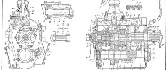
Rice. 4-4 Gearbox SAAZ-3206 1- primary shaft; 2- secondary shaft; 3.6- synchronizers; 4- cover; 5-control mechanism; 7- secondary shaft rear bearing cover; 8- speedometer drive worm; 9- secondary shaft flange; 10- nut of the secondary shaft flange; 11- speedometer drive; 12 - first gear and reverse gear; 13- intermediate shaft; 14 - second gear gears; 15- drive gear for reverse and power take-off; 16- third gear gears; 17- fourth (fifth) gear gears; 18- pair of drive shaft; 19-crankcase; 20 - input shaft cover; 21-gear intermediate reverse gear and power take-off.
To fill with oil, there is a filler screw plug in the right wall of the crankcase 19. To drain the oil, there is a drain hole in the left wall of the crankcase, at the bottom, closed with a magnetic screw plug.
Centering of the box is carried out along the flange of the primary shaft cover 20.
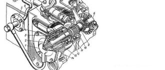
Gear shifting is carried out by the control mechanism lever in the cover 4 (Fig. 4-4) of the gearbox through rod 5 (Fig. 4-5) and gear shift lever 2 at the driver’s workplace.
If it is difficult to engage gears, it is recommended to adjust the drive by changing the length of the rod 5 by turning the fork 9 of the gear shift rod.
Rice. 4-5 Gearbox drive 1-lever handle; 2-gear shift lever; 3- hinge; 4- lever bracket; 5- traction; 6- bolts; 7- finger; 8-coupling; 9- fork; 10- gearbox; 11-shift lever
When servicing the gearbox
its fastening to the clutch housing and the fastening of the parts of the gearbox itself to the crankcase are checked; The oil level is replaced and maintained according to the lubrication chart.
When changing the oil, you need to clean the drain plug magnet and the breather. A clogged breather can cause an oil leak due to increased pressure in the crankcase.
When changing the oil, as well as when repairing the gearbox, do not allow contaminants to get into it, which can cause the gears to jam.
Source
SPECIAL OPINION
Conducting editorial tests on the test roads of the Federal State Unitary Enterprise NITSIAMT, you somehow forget that this is a place of increased concentration of new models of the global automotive industry. The streets of Moscow and highways aimed at Europe have recently turned into a permanent Motor Show and also cannot reflect the general situation on the roads of the entire country. And the homespun truth is that in the vast Russian expanses, the products of the former Automotive Industry and its bus component, in particular, will obviously rule the roost for a very long time. In Soviet times, regular KAVZs and PAZs, especially all-wheel drive ones, were the main means of suburban transport, especially in rural areas. Since then, PAZ has almost photographically preserved the appearance of its products and its leading position in the production of buses. If among the bus factories that found themselves in the abyss of perestroika processes, there was a prize “For the will to win”, then it would have been registered in the city of Pavlov on good grounds.
As for the interior and the driver’s workplace, they “brought together” at least three generations of passengers and drivers. Honored pensioners do not need to tell their grandchildren what buses they had to ride on, and a young, inexperienced driver may well take a master class from his father or grandfather, who drove Pavlovsk cars several decades ago. But the high need for PAZs in the country cannot be explained by continuity alone. In the technical and marketing aspects, dramatic changes have occurred, determined by the strategy, which, in addition to Pavlovsky, includes the Likinsky, Kurgan and Golitsynsky bus plants.
Today, along with the traditional gasoline bus, a diesel version is also offered, equipped with MMZ-245 engines in various modifications, which has an incredible impact on its fuel efficiency. Based on a preliminary assessment of the fuel consumption values obtained as a result of measurements, it can be assumed that the reduction in operating fuel consumption can be up to 10 liters, or in the advertising form “25 free kilometers” compared to a gasoline car.
Installing a diesel engine makes it easier to solve problems related to environmental requirements. The development of middle-class buses (PAZ-4234 - an extended version of PAZ-3205) also looks economically justified, which allows increasing passenger capacity from 37 to 50 people with minimal costs for changing production. The main direction of the strategy aimed at reducing production costs was the refusal to use energy-intensive stamping production and the transition to a tubular body frame with priority use of plastic external panels; a similar technology was tested on the new serial bus PAZ-4230 of the Aurora family, which is already widely represented on market. But there is one significant point: the price of the Aurora is approximately twice the cost of even the most expensive diesel version of the almost antique PAZ-3205. This means that our veteran still has hope for many, many years of working life. And either fortunately or unfortunately, we are not used to the general level of this machine.
Section 2. CONTROLS AND OPERATION OF THE PAZ-32053 BUS
CONTROLS AND CONTROL INSTRUMENTS OF THE PAZ-32053 BUS
The location of the controls is shown in (Fig. 2-1 a). To the right of the driver's seat are the gearbox control lever and the parking brake handle. The gear shift diagram is shown on plate 10 of the instrument panel and fig. 2-1 b.
Rice. 2-1 Controls: a – driver’s workplace; b – gear shift diagram. 1-end of the door locking rod; 2- bag; 3-door opening handle; 4-handle for driver's landing; 5- switch for headlights, direction indicators and sound signal; 6- instrument and starter switch; 7- switch for windshield wiper, windshield washer and sound signal; 8- instrument panel; 9-window defroster; 10 - plate with gear shift diagram; 11- radiator shutter control circuit; 12- fuse block; 13-gearbox lever; 14- engine hood; 15- hood fastener; 16- hood handle; 17- handbrake handle; 18- fuel supply control pedal; 19- brake pedal; 20 - cabin ventilation damper; 21-clutch pedal; 22-socket
Rice. 2-2 Diagram of the position of the instrument switch and starter key
Instrument and starter switch 7 (Fig. 2-1) is located on the steering column. In Figure 2-2. The diagram of the position of the instrument switch and starter key is shown:
“III” – in this position the key is inserted and removed from the switch. Regardless of whether the key is inserted or not, the steering shaft is locked with an anti-theft device, but you can turn on the hazard lights, door drive, portable lamp, turn on or off the batteries;
“0” – in this position the anti-theft device is disabled. To turn off the anti-theft device, you need to insert the key into the switch (position “III”) and, slightly shaking the steering wheel left and right, turn the key to position “0”.
“I” – in this position, control and measuring instruments operate and switching on of electricity consumers is possible.
“II” – in this non-fixed position the starter is turned on.
To turn off the devices, turn the key from position I to the fixed position 0.
To avoid failure of the contact part of the instrument switch, do not leave the key in an intermediate position.
Switch for headlights, direction indicators and horn. The switch lever has six fixed positions (Fig. 2-3) - I, II, III, IV, V, VI and four non-fixed positions “A”.
Groove gearbox shift diagram
The GAZ-53 truck is perhaps the only car that has not been produced for 20 years, but is still in use by most people and enterprises. This is all thanks to the high-quality assembly and the parts used from which the individual components of the truck were created.
This is what the original GAZ 53 looks like
The gearbox diagram is constructed as follows. The front end of the input shaft is fixed in the bearing of the engine crankshaft, the rear end of the shaft is connected to the secondary shaft through a needle bearing.
The intermediate shaft transmits all movements to the secondary shaft; depending on the selected speed, the gear ratio changes and, accordingly, the speed at which the car moves. The fourth gear is direct; in this gear, the clutch connects the primary and secondary shafts.
Example of a gearbox for GAZ-53
From the shank of the secondary shaft, through the propeller shaft, the movement enters the rear axle, which rotates the rear wheels.
Kamaz gearbox device
For KAMAZ vehicles, two types of gearboxes are produced:
- Model 14 - 5-speed;
- Model 15 - 10-speed.
The 14th model is for single vehicles, the 15th is for a road train.
The 15th model of the KAMAZ gearbox, in which 10 gear shift speeds are the same five-speed gearbox of the 14th model plus a gear divider. The design of the rear axle gearbox of a passenger car differs from the design of the divider gearbox. The design of the gearbox-divider together with the gearbox of model 14 creates 10 forward speeds and 2 reverse speeds.
Pros of boxes with a divider:
- The switching frequency becomes lower. You have to switch less often.
- The thrust of the internal combustion engine of the car increases.
- Ease of control increases.
To obtain permission to drive trucks over 3.5 tons with trailers, you must meet certain requirements. Find out how to open category E.
Since KAMAZ vehicles are classified by purpose, that is, for transporting heavy loads, for such models the automobile plant made 14 modernized models out of the box, which is called KPP 152.
What improvements have been made to the old 5-speed gearbox:
- Synchronizers have become more reinforced.
- A new gear mount was added to the design.
- To avoid the 4th and 5th speeds slipping out, which happens with conventional KAMAZ gearboxes, 4 degrees were added to the system to thin the teeth.
- The gearbox splines have also become more reinforced.
- The control scheme has been improved.
- The spline mount has been removed.
- The height of the teeth has been increased.
The divider receives the load from the pneumatic system and is controlled by it. In new KamAZ vehicles the design is more complex, so it is advisable to repair the gearbox and divider in specialized service stations.
TRANSMISSION OF KAMAZ VEHICLES - PART 3
The remote drive for controlling the main gearbox (Fig. 138) consists of a swing lever 4 for gear shifting, support 2 for the gear shift lever mounted on the front end of the engine cylinder block, front 10 and intermediate 17 control rods, which move in spherical bushings 13 made of metal-ceramic, the bushings are sealed with rubber rings 12 and pressed by a spring 14 to the crayon 11. The spherical supports of the front link are located in the bore of the support bracket 2 and in the flywheel housing. The intermediate link support is installed on the clutch housing. An adjusting flange 18 is screwed onto the rear end of the intermediate rod and secured with two coupling bolts 24.
The gear shift lever support (Fig. 139) consists of bracket 1, corrugated hatch seal 5, seal spring 6, shortened gear shift lever 4, which with its spherical part rests on a polyurethane bushing 7, which dampens vibration of the lever. The sphere is pressed from above through support washer 2 by a spring. Set screw 8 secures the shift lever in the neutral position when adjusting the drive. In the working position, the bolt must be unscrewed and secured with a locknut.
The remote drive for controlling the main gearbox of model 15 differs from the drive of the gearbox of model 14 by an extended intermediate rod and a gear shift handle in which switch 3 (see Fig. 138) of the divider control valve is mounted.
The pneumatic gear shift system of the divider (Fig. 140) consists of the following main assembly units: pressure reducing valve 4, control valve 3, gear shift mechanism 5 of the divider with air distributor 6, valve 1 for switching on the gear divider, valve stop 2 and air ducts.
Air from the receiver of the IV circuit of the drive of the auxiliary brake system at a pressure of 608...736 kPa (6.2...7.5 kgf/cm2) is supplied to the input of the pressure reducing valve 4, at the outlet of the valve a constant pressure is maintained equal to 387...436 kPa ( 3.95…4.45 kgf/cm2), the value of which is regulated by spacers installed on the spring housing.
Divider control valve 3 (see Fig. 140), depending on the position of the spool, directs the air coming from the pressure reducing valve into one of the cavities under the pistons of the air distributor 6 and moves the air distributor spool to one of two extreme positions, thus preparing the air supply into cavity A or C of the power cylinder.
Preliminary gear selection in the divider is made by moving the valve switch lever to position B or H, which moves the valve spool through a braided cable.
The air supply from the pressure reducing valve under the piston of the power cylinder is carried out by the valve (Fig. 141) for switching on the gear divider, the opening of which is carried out by stop 2 (see Fig. 140) attached to the piston pusher of the pneumatic hydraulic booster for clutch release. The valve opens at the end of the pusher stroke, that is, when the clutch is completely disengaged.
Rice. 138. Drive for controlling the gear shift mechanism: 1 — divider control valve; 2 — gear shift lever support; 3 — tap switch; 4 — gear shift lever; 5 — control valve cable with braid; 6 — front control rod head; 7 — tip lever; 8, 22 — locknuts; 9, 21 — installation screws; 10 — front control rod; 11 — ball joint block; 12 — sealing ring; 13 — ball joint bushing; 14 - spring; 15 - cover; 16 — front linkage lever; 17-intermediate rod; 18 — adjusting coupling flange; 19 - bolt; 20 — support; 23 — gear lever rod; 24 — bolt for fastening the adjusting flange
contents .. 41 42 ..
Creation of the GAZ 53 checkpoint
The first releases of the GAZ 53 (with the index “F”) were equipped with a six-cylinder engine and a GAZ 51 rear axle. The gearbox was also taken from the 51st, but it was modernized. It should be noted that it is possible to replace the GAZ 53 gearbox with a GAZ 51, but it does not always make sense to do this. The fifty-first box has different gear ratios. In addition, it is designed for a less powerful engine and lower load capacity.
Due to the fact that the production of the GAZ 53F was discontinued in 1967, the old modification was replaced by the improved GAZ 53A.
This car was already equipped with a powerful V-shaped 8-cylinder engine, so a new rear axle had to be designed on the new model and the gearbox had to be improved.
Example of a GAZ 53F truck
On earlier versions of the gearbox, synchronizers for the third and fourth gears were installed, which are designed to smooth out the moment the gearbox is engaged, but in later versions of the gearbox the synchronizers were removed, considering them unnecessary. All that's left is the shift clutch. Gearboxes without synchronizers began to be used on the GAZ 3307.
Diagram of the GAZ-53 gearbox
Here we will talk about the gearbox of the famous GAZ 53 truck.
Design and diagram of a gearbox from a GAZ 53 truck.
The gearbox on this truck has four forward speeds and one reverse. It is mechanical, consisting of three shafts: drive, driven, intermediate. The GAZ 53 gearbox is designed for three strokes.
Thanks to the gearbox, it is possible to transfer the speed that the engine develops to the drive wheels, while changing the amount of traction force. If necessary, using the gearbox, you can stop transmitting these revolutions to the drive wheels. This corresponds to the neutral position of the gear lever.
Positions of the GAZ-53A gearbox shift lever.
Car reference book
A wide range of trucks, especially vehicles for intra-city and long-distance transportation, as well as transportation of construction materials, requires the creation of gearboxes specifically designed for such operating modes.
Listed below are the various design types of manual transmissions developed by ZF for trucks for various purposes. They are divided into 3 groups:
- Ecolite gearboxes: 5 gears (for light trucks with engines from 50 to 120 kW);
- with 6 gears or 12 steps (for medium-class trucks with engines with power from 110 to 180 kW);
- with 9 gears or 16 steps (for middle-class trucks with engine power from 180 to 240 kW);
- with 16 stages (for heavy trucks with engine power from 220 to 400 kW).
Important distinctive features of these gearboxes:
- High specific weight due to light alloy body and compact design;
- Low and even shifting forces thanks to the latest short-throw and double-cone synchronizers;
- Wide range of gear ratios with optimal gear gradation;
- Availability of options with direct or overdrive top gear.
The Ecolite series includes, for example, the S 6-66 model, designed to transmit torque up to 750 Nm (Fig. 46 “ Six-speed transmission of the Ecolite series, model S 6-66 ”).
The maximum gear ratio that can be achieved using a six-speed gearbox is i = 9.0.
Long haul trucks use six-speed transmissions with an integrated front splitter. This additional gear train, located in front of the main gearbox, provides - as shown in Figure 47 " Six-speed gearbox with integrated front splitter " - a second constant gear ratio, which is most often designed as an overdrive gear with i - 0.83.
The alternating engagement of two constant gear ratios L and S (“slow group” - “fast group”) doubles the available six gearbox stages, that is, each gear ratio interval is divided in half, resulting in the entire range of gear ratios being divided into 12 steps.
In this way, the divider unit makes driving more economical, always ensuring the selection of the “ideal” gear and thus the correct ratio of engine power to driving mode.
To better understand the above, please see Table 4, “ Gear Ratios with and without Divider ” and Figure 48, “ Split and Simultaneously Expand the Range of Gear Ratios with Built-in Divider ,” which illustrate the separation (L and S) and simultaneous expansion of the range of direct ratios. transmission (9.06-1.0) due to the built-in divider unit with i = 0.83.
Figure 49, “ Six-speed transmission design of the S 6-66 model and the transmission of torque in different stages, ” shows the transmission of the S 6-66 with an integrated front divider and the transmission of torque in separate gears in slow (L) and fast ( S) groups.
The divider is controlled using a pneumatic drive and a control system, which - as can be seen from Figure 50 “ Principal diagram of a pneumatic drive for switching stages of the divider ” - consists of a divider control valve (1) on the gear shift lever, a start valve (10) controlled by the clutch pedal , and a double-acting working cylinder (12) with built-in relay valve (11).
Before changing gear, the driver, using the control valve (1) and accelerator valve (11), selects the required group (L or S) of the divider. Only after the clutch is completely disengaged, the start valve (10) activates the supply of compressed air to the working cylinder (12) and further gear shifting is carried out in accordance with the selected group.
Ecomid series gearboxes have an integrated rear divider. Nine-speed modifications of this series, used primarily on trucks for transporting construction materials, are a block of four gears with a separate reduction gear by sliding gears and an additional rear divider in the form of a planetary gear. An example of such a design is the gearbox of the model 9 S 109 (Fig. 51).
By connecting a rear splitter, the number of gears in a block of four gears is doubled. This produces two shift positions - “slow group” (L) with gears 1-4 and “fast group” (S) with gears 5-8. Thus, together with the reduction gear, the driver has a total of nine sequential forward gears at his disposal. The torque transmission diagram is shown in Figure 52.
The operation of the planetary gear as a rear divider is carried out as follows (Fig. 53 “ Planetary gear design ”). When the divider control valve is in position "b", the ring gear (1) remains stationary. Driven by the sun gear (secondary shaft) (2), the planetary gears (3) - and thus the planetary carrier (input shaft) (4) - roll over the stationary ring gear.
This creates the following gear ratio (using the example of the 9 S 109):
i = Zring gear / Z sun gear +1 = 86/34+1 = 3.53
“+1” is due to the fact that the planetary carrier makes one revolution, while the sun gear makes 2.53 revolutions.
When the splitter control valve is moved to the “S” position, the ring gear is rigidly connected to the planetary carrier. As a result, the planetary gear operates as a single unit without changing the gear ratio (i = 1.0).
In gearboxes with a rear divider, the main gears are switched using a mechanical drive, and the divider groups are switched using a pneumatic mechanism. In this case, there are two different gear shift patterns (Fig. 54 “ Shift patterns in a four-speed gearbox with a rear divider ”).
When shifting with double H, each individual gear corresponds to a specific position in the gear shift pattern (Fig. 54 on the left). In this case, switching of divider groups L and S is carried out automatically when changing channel 3/4 to 5/6, that is, when switching from fourth to fifth gear or vice versa.
When shifting with overlay H (Fig. 54 on the right), positions 1-4 of the gear shift lever correspond to two gears. This means that when shifting from fourth to fifth gear or vice versa, the splitter group must first be selected using the splitter control valve on the shift lever.
The control system for shifting with double H is shown in Figure 55 “ Diagram of the basic design of the gear shift mechanism according to the “double H” scheme .” It consists of a changeover valve (1) and a double-acting working cylinder (2) integrated into the gearbox. The shift valve is activated by the control shaft (3) of the main four-speed transmission unit and only releases the compressed air supply to the working cylinder when the gearshift lever is in neutral.
When installed on long-haul trucks, a gearbox with a rear splitter is combined with a front splitter, which in this case is installed in front of the four main stages (without reduction gear).
In this way, you can get a gearbox with 16 steps (2x4x2 =16) (Fig. 56 “ Gear ratio steps for a gearbox with front and rear splitters (without reduction gear) ”).
Malfunctions of the GAZ 53 gearbox
Symptoms of a problem
A faulty gearbox can be judged by the following signs:
We have long wanted to test the most “people’s” bus, PAZ-3205. Since Soviet times, the main consumers of the PAZ-3205 were villagers who used these buses to travel from remote villages to regional centers. Various modifications of the PAZ-3205 are widely used for transporting construction workers, factory workers, and shift workers at oil and gas developments. In small towns, “pasikis,” as they are affectionately called by people, operate regular buses. Even beyond the Arctic Circle they have found application. And recently they have mastered another “profession” - minibus taxi in large cities. So the PAZ-3205 is a popular and truly “people's” bus. What are the buses of the Pavlovsk plant?
Many of our readers were probably surprised by the question posed - “grooves” have been coming off the assembly line for a long time, and have been used by numerous customers for many years. And why test buses that everyone already knows? One could agree, but...
PAZ-32053 with a gasoline engine ZMZ-5234.10
It is probably incorrect to compare the car of today with its “brother” from six years ago in terms of power unit. At that time we were dealing with a completely new car, the same sample had been tested a long time ago, and all the “childhood diseases” were eliminated by the PAZ drivers during operation.
The engine idles quietly. The noise is created only by the pneumatic compressor, and the squelching sound of the operating compressor is similar to the squealing of a black grouse. But when the engine speed increases, a characteristic sound appears, somewhat reminiscent of the operation of the engine of an old GAZ-53 truck. Naturally, in this case you can no longer hear the pneumatic compressor.
The starting dynamics of the petrol PAZ are quite good - the engine power is still 130 hp. With. The gearbox engaged in gears without problems, except for two – fifth and reverse. For some reason, the fifth gear was engaged all the time with a “breakdown”, i.e. with a slight grinding sound, the reverse gear was also difficult, but for a different reason - there was not enough space.
And the road dynamics of the PAZ-32053 are good. To my surprise, the gas pedal worked without problems: like on imported cars, without delays and smoothly. Therefore, it was not difficult to maintain a constant speed during fuel consumption measurements.
Until 2003, PAZ buses were equipped with a braking system consisting of two circuits: hydraulic and pneumatic, like on trucks from the Gorky Automobile Plant. Since 2003, Pavlovsk residents have modernized the braking system, and it has become completely pneumatic, which made it possible to install ABS from Knorr-Bremse.
But the location of the brake pedal remains inconvenient: it is installed at different levels with the gas pedal.
The hydraulic clutch pedal is poorly positioned - very high. In city traffic jams, when the driver constantly keeps his foot on the clutch pedal, the inconvenience turns into leg pain. By the way, our version is also confirmed by the drivers of PAZ “route” taxis operating in cities. On suburban routes, PAZ drivers do not have this problem: they don’t have to keep their foot on the clutch pedal for long.
As for maneuverability, Pavlovsk buses have always been distinguished by good handling and maneuverability. Suffice it to say that with an overall turning radius of 8.5 m, the bus turns on a road 6 m wide in two steps. It should be noted that the power steering worked well - with such a turn, you had to turn the steering wheel in place. On a gasoline “groove” the power steering worked silently and easily.
There were no complaints about the chassis during testing either. Buses PAZ-32053 and PAZ-32053-07 are equipped with bridges from the Ryazan Automotive Units Plant (RZAA) or the Kanash Automobile Units Plant (KAAZ). In our case, bridges made in Ryazan were installed on both grooves. Apparently, this is why the gearboxes did not emit the characteristic howling sound inherent in the axles of Gorky trucks. The Ryazan plant also produces rear axles for the Moscow ZIL automobile plant.
Diagram of operation of a gearbox with a divider
Most KamAZ trucks in use today are equipped with five-speed manual transmissions. The gear shift pattern in such gearboxes is quite familiar: the driver depresses the clutch and moves the lever to the required position. It is important to understand that KamAZ vehicles are heavy-duty trucks, that is, adjusting the position of the lever must be done strictly in stages.
gearbox and divider switching diagram
The typical transmission modes for a truck with a diesel engine are low (“H”) and high (“B”) operating modes. The development of these two options was carried out specifically in order to minimize the load on the engine of the machine, both with a maximum load and when empty. Many KamAZ vehicle models allow you to switch these modes without using the gearshift lever.
The driver just needs to raise or lower a special divider switch and literally squeeze the clutch for a second.
The mode is adjusted automatically: a lowered switch activates a light driving mode, and a raised switch activates a stronger driving mode.
Dealing with switching gearbox modes on KamAZ trucks is relatively simple. To change gears 1-5, use the corresponding lever located to the right of the driver's seat. For example, acceleration of a truck involves the use of the following gear shift pattern: 1B-2B-3B-4Н-4B-5Н-5B . On a clogged highway or in difficult road conditions, use 1H-2H-ЗH-4H-4В-5H-5В .
It should be borne in mind that the KamAZ gearbox device allows you to change speeds only if the clutch is disengaged. To switch from the upper mode to the lower one and vice versa, you need to move the switch to the appropriate position and only then press the clutch all the way and as sharply as possible. Literally in a second you need to release the pedal for the desired main gear to engage.
During the operation of the vehicle, it is very important to monitor how much oil is in the KamAZ gearbox, and, as necessary, add lubricant in a timely manner, preventing possible problems and malfunctions.
PAZ-32053-07 with a Minsk diesel engine
Everything that has been said about the design and layout of a bus with a gasoline engine is fully true for a car with a diesel engine. The main difference is the Minsk-made MMZ D-245.7 engine. It’s hard not to notice him when standing next to a bus with its engine running. You can immediately say: “He! Tractor "Belarus". PAZ specialists worked for a long time to reduce the noise of not only the engine, but also the entire bus as a whole, and as a result, its level was brought to the required certification standards, but the feeling of a tractor engine remained.