The power take-off shaft powers the attachment. MTZ-80 has 2 drives: two-speed independent (540 and 1000 rpm) and synchronous:
- With an independent drive, the PTO will operate both while driving and when parked.
- The synchronous drive depends on the speed of the tractor, so it will not work when stopped
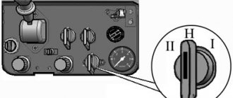
The PTO control system is used to switch the transmission mode:
Independent ⇄ Synchronous
The most common problem is the breakdown of parts for controlling the power take-off shaft. Spare parts for the PTO can be purchased at https://tractorsouz.com.ua/ at a favorable price and with delivery.
PTO diagram of MTZ 80 and 82
Below we present a diagram of the drive of the rear power take-off shaft for tractors of the MTZ 80 and 82 models, and we will give its explanation.
The main mechanisms of the rear PTO include: 2-speed gearbox, drive type switch, mechanical gearbox, dependent or independent type switch.
The rotation speed of the independent power take-off shaft is switched using a clutch (5), which is installed on the shaft spline (6). And the mechanism that is responsible for this is a hexagon, it is located in the lower cover of the one-piece clutch housing.
The lever (18) has 3 positions: clockwise rotation - dependent type, anti-clockwise - independent, middle position - neutral. Remember that the synchronous type should only be turned on when the engine is not running or the minimum crankshaft rotation speed, but the synchronous type only when the tractor is stopped.
Planetary PTO gearbox MTZ 82 and 80
This mechanism is one of the important components, so we will dwell on its design in more detail.
this mechanism is designed to control the power take-off shaft and has a gear ratio of 1.47. Its components: drive crown (17), satellites (18), sun gear (19). The satellites are installed on the axles (16), which are pressed into the carrier bore.
On special order, the plant can produce the shaft (15) as a composite one, i.e. special shanks (25) with 8 (for 540 rpm) or 21 (for 1000 rpm) splines can be inserted into its rear end for various implements.
As you can see, the diagram is quite simple to understand.
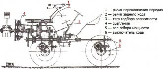
Side take-off shaft for models 80 and 82
Below is a diagram of the side power take-off shaft for these tractor models.
In this case, everything is even simpler, the drive is carried out through a movable gear wheel (2), and the gear itself moves along the splines using a driver (6). The side shaft can only be engaged when the clutch is disengaged using rod 3.
What is PTO?
The abbreviation PTO stands for power take-off shaft, which is installed on the MTZ-80 tractor or similar MTZ-82 to provide drive for mounted systems and units.
PTO shank
According to the installation method, the PTO can be of a side or rear type. The most optimal are rear-mounted power take-off shafts. They are installed on most wheeled vehicles and on the MTZ-80 tractor in particular. According to the principle of operation, the PTO of the MTZ-82 tractor can be of three types:
- Synchronous. In other words, such a shaft is called dependent. The speed of the unit directly depends on the mode of movement of the equipment. The drive to the power take-off shaft comes directly from the gearbox gearbox. The average rotation speed is 3.5 revolutions/1 meter of travel.
- Independent. Such a mechanism is connected directly to the MTZ-82 engine. Its rotation frequency depends on the engine flywheel with which the tractor is equipped. In addition, whether the clutch is on or off plays a role. For MTZ-80, the shaft rotation speed is 540 or 1000 rpm.
- Combined. Such a PTO can operate in the two modes listed above.
A little history
The MTZ series of universal tractors began to be created in the 1970s after a special resolution of the USSR Council of Ministers. The government decided to introduce a powerful row-crop tractor (up to 80 hp) into the agricultural sector. The development base was a modernized version of the MTZ-50 tractor. Many configurations were introduced into the design of the vehicle; the casing and cabin underwent modernization.
The MTZ tractor series began to be created in the 1970s
A new engine with increased power was installed on the tractor. In 1972, the first tests of the MTZ-82 turned out to be very successful. Based on the test results, a list of aggregated equipment was created; in total, more than 230 devices were created for various types of work. The acceleration of the tractor up to 30 km per hour made it likely to be used for transport work.
The first tractor left the assembly line of the Minsk plant in 1974. The first reviews of MTZ 82 were positive. And Belarusian tractor manufacturers began to increase production volumes. For almost four decades, the equipment of the Minsk plant has cultivated fields on almost all continents of the world. They are especially popular in developing countries of Asia, Africa, and Latin America.
PTO adjustment for MTZ-80 and 82
If you are not familiar with the complete device or do not understand the operating principle of the PTO for MTZ-82 and 80, then we recommend that you read the previous material. But if there are no “problems” with this, then let’s get started.
Quite often (almost always) after replacing the brake bands, it is necessary to adjust the PTO control mechanism as a whole; to do this, follow these instructions, but first let us recall two diagrams:
Rear power take-off shaft control.
Planetary PTO gearbox.
Now you can safely begin:
1. Set the eccentric axis (2 – 15) to its original position, so that the “I” flat is vertical to the right. We fix it with a locking plate (2-17) and bolts (2-16);
2. Disconnect the rod (4);
3. Turn out the bolts (9) and thereby release the springs (6);
4. Remove the rear axle hatch cover, this will give us access to the screw (13);
5. Fix the lever (11) in the neutral position; to do this, you need to insert an M10X60 bolt into the hole on the lever in the rear axle housing;
6. Remove the locking plate (2-26), and tighten the screw (2-21) until it stops;
7. Remove the bolt (10) that holds the lever (11) in the desired position;
8. We tighten the bolt (9), guiding it in the recess of the glass (7) to dimensions “A” from 26 to 30 mm;
9. Set the position of the lever (11) to the “on” position;
10. Set the rod (4);
11. By adjusting rods 11 and 15, we place the required swing zone of the lever (1) in the middle part of the slot in the control panel.
Upon completion of the PTO adjustment, we replace the plate (26), the hatch cover, counter rods (4, 15) and the bolts themselves (9).
Adjusting band brakes MTZ-82 and MTZ-80
If during operation you notice that:
• PTO slippage occurs;
• When the control lever (1) is switched, it rests on any part of the slot;
• To turn it on, a force of more than 15 kgf is required;
• There is a “fuzzy” fixation in the most extreme positions or its movement is uneven when on/off.
Then you need to adjust the band brakes; to do this, follow the instructions below:
1. Place the lever (11) in the neutral position, while fixing its position, as in the previous point 5;
2. Turn out the pain (2-16) and remove the plate (17) from the slot of the axle shank (15);
3. Using an open-end wrench set to 13, turn the axis (15) clockwise until the gap between the belt and the PTO drum is selected;
4. Place the plate (17) in its “right” place and tighten the bolts (16);
5. Remove the locking bolt from the lever (11).
If you make a couple of external adjustments, then the axis (2-15) may take the leftmost position, this indicates that the external adjustment reserve has been used up. Then we put it in its original position, turning it counterclockwise, and carry out the adjustment as per the instructions above.
If the adjustment is carried out correctly, then the lever (1) should not reach the position (on or off) from the edge of the slot by at least 3 cm and strictly occupy the center position.
Practical tips for use.
The design features of the drive shafts of the machines used often have the character of open, actively rotating parts. To avoid injuries and emergency breakdowns when working with drive machines, you should be careful and take into account the following aspects and rules:
- The machine coupled with the tractor must be in good technical condition.
- The machine must be used strictly for its intended purpose and in appropriate conditions. When preparing for PTO operation, you need to make sure that the splines of the shaft shank and the drive coupling of the machine used match (8 splines or 21). If there is a discrepancy, the shaft shank must be replaced.
- Check the presence and reliability of fastening of protective covers, rotating parts of the drive machine, adjustment of the safety clutches and serviceability of the cardan joints of the drive.
- The drive is installed directly at the place where the unit is used. The connection is secured with a special locking bolt when the recess on the shaft splines coincides with the hole in the coupling of the cardan drive of the machine being aggregated.
- The route and turning radius must correspond to the design features of the unit.
- In order to avoid overloading the unit structures, the choice of movement speed, processing depth, working width, and operating mode of the unit must comply with the standards and requirements.
- Disconnection is done after the shaft has completely stopped in the neutral position of the drive mode switching lever and the PTO is turned off.
With an optimal balance of engine speed and load, a significant reduction in fuel consumption per unit volume of work done by the unit is achieved. If the agrotechnical and technological conditions of the work do not limit the speed of the unit, the gear is selected based on the optimal load without signs of overloading the tractor and the mechanisms of the drive machine used. When working with energy-intensive machines with insufficient engine power, in a situation where the unit’s performance is not fully loaded at speeds above 7 km/h, a gearbox reduction gearbox is used.
Peculiarities of operation of the MTZ-82 tractor with machines requiring drive from the rear PTO
General recommendations:
a) before connecting the machine to the tractor, make sure that the rear PTO control is adjusted correctly (see 7.6.7.);
b) install and securely fix the required (8- or 21-spline) PTO shank and turn on the corresponding speed drive, while for the 8-spline shank set 540 rpm, and for the 21-spline shank - 1000 rpm.
To replace the PTO shaft end, do the following: unscrew the four nuts, remove the protective casing and plate; unscrew the six bolts securing locking plate 1 (Fig. 29), remove locking plate 1 and remove shank 2; install the other shank into the bore and secure it with locking plate 1, tighten six bolts; install the plate, casing and secure them with nuts. Engage the independent PTO drive at minimum diesel speed or when the diesel engine is stopped. Engage the synchronous PTO drive with the diesel engine running and the clutch engaging smoothly.
Fig.29
When operating the tractor without using a PTO, be sure to set the PTO control lever to the “PTO off” position, the shift clutch of the two-speed PTO drive to position 1 (at 540 rpm), and the switch lever from independent to synchronous PTO drive to middle (neutral) position;
c) lubricate the shaft and telescopic connection pipe of the cardan transmission with grease. Install the universal joint on the PTO shaft end and securely fasten it in the locking groove. Make sure that the forks 1 (Fig. 30) of the hinges of the intermediate (telescopic) shaft lie with their ears 2 in the same plane. Failure to comply with this requirement causes overload of the cardan transmission and PTO;
Rice. thirty
d) install the driveshaft casing of the agricultural machine;
e) after installing the cardan transmission, make sure that there is no resistance to the elements of the telescopic connection of the cardan transmission at the extreme positions of the machine relative to the tractor; the minimum overlap of the telescopic part of the cardan transmission should be 110-120 mm, since with a smaller amount of overlap the transmission may open.
The length of the spring 1 of the safety clutch of the agricultural machine (Fig. 31) must be adjusted so that when overloaded, the cam clutches 2 and 3 rotate relative to each other. Excessive tightening of the spring leads to failure of the clutch and overload of the cardan transmission and PTO;
Rice. 31
f) engage and disengage the PTO smoothly, without jerking, at a low speed of rotation of the diesel crankshaft;
g) before starting, check the operation of the machine at low and maximum speed of the diesel crankshaft;
Tractor movement with the PTO synchronous drive engaged is allowed at a speed of no more than 8 km/h;
h) turn off the PTO when turning the unit (for trailed machines), as well as when lifting the machine into the transport position (for mounted and semi-mounted ones);
i) after uncoupling the machine from the tractor, do not leave the universal joint on the PTO shaft;
j) when installing a drive pulley, as well as drive gearboxes of special machines (cotton-growing machines, excavators, etc.) on the rear PTO cover, make sure that they are centered relative to the shank (placed in a 0162 mm bore on the rear cover), and their fastening nuts are securely screwed.
When working with rotary tillage machines:
a) monitor the serviceability and normal operation of safety devices;
b) do not engage the PTO with the working tool lowered to the ground;
c) lower the machine with rotating working parts smoothly while the tractor is moving;
d) do not engage the PTO when the angle of refraction in one of the universal joints is more than 35 degrees;
e) when working on hard soils, cultivate transverse strips to enter the paddock, only after that cultivate the field in the longitudinal direction.
..
22
23 ..
Carburetor of MTZ-09N walk-behind tractor
If, after purchasing such a device, malfunctions begin, then it’s time to get the carburetor tuned. This happens when the unit sits for a long time and is not used. It is very easy to do; you need to tighten all the bolts as tightly as possible, and then unscrew them half a turn. Using the lever, turn on the minimum speed. A screw is used for adjustment and this should be done at idle speed; it is important that no extraneous noise comes from the motor. If you unscrew the fuel screw, the fuel supply will increase, but vice versa it will decrease.
Video 505 vm.-77 MTZ-50 MTZ-50 year of manufacture 1977 major overhaul
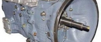
coupling
Upon visual inspection, oil smudges are visible on the shaft cover
This indicates wear of the cuff or gasket. In this case, the shaft is dismantled and the gasket between the PTO cover and the rear axle is replaced. If the leak comes from the shank side, the stopper ring is removed, the shaft is pressed out and the cuffs are replaced.
The MTZ-80 tractor does not produce maximum power when working with attachments
The probable cause is the band brakes. They need adjustment or complete replacement. If the adjustment does not help solve the problem, it is necessary to remove the PTO from the tractor and measure the thickness of the brake bands. If the thickness is less than 2.5 millimeters, the tapes are replaced.
At maximum load on the tractor, extraneous noise is heard
This indicates wear of the satellite axles, support bearings or splined joints. The technical condition of these components can be assessed only after the PTO is removed from the tractor. After this, the teeth are inspected and the gaps are checked. If repair is possible, the parts are restored; if not, they are replaced.
If the speed reducer gearbox has been dismantled or disassembled, the PTO will need to be checked or adjusted. To do this, place the tractor on a jack (under the drive wheels) and turn the take-off shaft, alternating the gears.
When performing this operation, the tractor PTO must be switched to synchronous mode. When scrolling, the gear wheels should rotate freely.
Attention, TODAY only!
Similar
Possible faults
Possible breakdowns, repairs and malfunctions:
- Jamming of the shaft handle on machines: turning on requires a lot of effort from the driver. In this case, it is recommended to inspect the spring cup or cam-type coupling for damage and wear of parts.
- Increasing extraneous noise as torque increases. Such a malfunction may be associated with wear of the PTO splines and elements of the planetary gear mechanism. It is also worth inspecting the cuffs for elasticity and damage.
- The shaft is unstable and jerky. The breakdown may be related to the splined connections of the mechanism. Either the gear moves too freely along the base, because her teeth were worn out. It is necessary to disconnect the rear axle from the dog clutch. Inspect the width of the gaps. If the gap is too large, it is recommended to replace the shaft.
- The engine is not running at full power. The band brakes should be replaced and adjusted.
- The tail shaft moves too freely. In this case, it is recommended to tighten the loose nuts. Threads may need to be replaced.
General device
The power plant is diesel. The engine is 4-stroke, 4-cylinder, with a design power of 82 horsepower. Engines are also produced at Minsk Tractor Plant. In Minsk engines, the combustion chamber made in the piston is divided in half. Tractor models with a pre-heater are also available on the market. The total engine volume is 4.75 liters, the speed reaches 22,000 rpm.
The main brakes and parking brakes are on discs, dry. Pneumatic brake drive for trailers. Locks with car brakes. Electric current for the tractor is generated by a 700 W generator set with a voltage of 14 V. A starting system with a voltage of 24 V can be supplied upon request. The driver's workplace is comfortable, the cabin is isolated from noise, and good visibility is provided.
All tractors are equipped with a mechanical transmission. The 9-speed MTZ 82 is equipped with a reduction gearbox and has 22 gears - a total of 18 forward, four rear gears.
The rear wheels are placed on a rigid suspension and mounted on a semi-rigid one. Rubber for MTZ-82 is also supplied by Belarusian manufacturers. If the farmer is put off by the price, there is always a large selection on the secondary market.
Production
Delivered to tractor dealerships,
mainly assembled by the Minsk Tractor Plant. But in the near future, Belarusian tractor manufacturers are intensively entering into production cooperation, opening assembly lines, developing their network of equipment maintenance points, and increasing the supply of spare parts.
In Russia there is an assembly facility in Saransk, which is based on the installation of Belarusian-designed tractors from ready-made components and assemblies supplied from the head assembly flow. Locally assembled Russian cars from finished Belarusian-made parts are somewhat cheaper.
Increasing the speed of Belarus
To get maximum efficiency from the purchased MTZ walk-behind tractor, many owners are interested in the possibility of increasing the speed of the unit. Experts recommend replacing the standard gears with accelerated gears. The difference is in the number of teeth. A regular gear has 61 teeth, and the axle shaft has 12. The accelerated gear is slightly different and has 55 teeth, and the axle shaft has 15.
The principle of operation is to increase the speed of rotational movements of the axle shaft, and, consequently, the entire unit as a whole. Moreover, the engine speed does not change. For example, in 4th gear after replacement, the speed will increase from 9 km/h to 15 km/h.
One simple but effective way to increase the speed of the MTZ walk-behind tractor is to replace the wheels with larger diameter ones. The explanation is simple - the increased wheel area covers a larger area.
Advantages and disadvantages of the tractor
During operation, the costs of maintaining a Minsk tractor are minimal. And this is the main factor that is valued by farmers. The car has high reliability. And on Russian fields, the tractor is in no way inferior in productivity to its European counterparts. And sometimes even surpasses them. Over the years, the Minsk tractor has gained a reputation as “indestructible equipment”, which cannot be affected by off-road conditions, temperature changes, dust, heat, rain, snow and frost.
The tractor is easily aggregated with a large number of attachments. Easy to use. The developers tried to create a certain level of comfort for the driver in the cabin (as far as this word is applicable for cars developed during the USSR). The machine meets modern ergonomic standards.
Disadvantages and typical problems
In general, the engine is insensitive to fuel quality. But if the quality of diesel fuel is poor, the diesel engine may stall and not start at all. What to do? The problem is often solved by adjusting the injectors and changing diesel fuel.
If there is black smoke from the exhaust pipe, immediately reduce the load on the engine. If white and blue smoke occurs, it is necessary to carry out maintenance of the fuel system and adjust the thermostat.
A particularly alarming symptom of the “health” of equipment is knocking in diesel engines. You should stop work, carry out diagnostics, and replace severely worn rings and bushings.
If oil consumption is excessive, worn parts are also replaced and piston rings are replaced.
Carrying out running-in of MTZ
It is necessary to carry out a break-in after purchasing a new walk-behind tractor before putting it into operation. The importance of break-in is to allow the parts to break in. Since the walk-behind tractor that comes off the assembly line is not run-in in production, all parts may not fit tightly due to possible roughness on the surface. Therefore, during the running-in of the MTZ, no attachments are used, and the unit is started only at half power. You should not operate it at maximum speed.
The manufacturer recommends running-in for 10-15 hours.
The engine starts and at first it just runs, then gradually the load needs to be added. Do not use a heavy hitch. All you need to do is connect the trailer without any load and go for a ride with it.
Dismantling and repair of the power take-off shaft of the MTZ-80, MTZ-50, YuMZ-6 tractor
If you notice that the power take-off shaft control lever is jammed, or if it is difficult and difficult to control the shift clutch driver to an independent or synchronous drive, you should pay attention to the boost mechanism (spring cup) and the claw shift clutch. Most likely, it has exhausted its resource and has fallen into disrepair
To finally clarify all the circumstances, remove the reinforcement mechanism and disassemble the spring cup as in Figure 2.8.20.
The glass must be disassembled in a certain sequence. First, install the power take-off shaft control lever (hereinafter simply PTO) in a position where the technological holes in the lever 5 of the shift shaft and the rear axle are aligned, and tighten the adjusting bolt 1 into them. Then loosen the lock nut 3, tighten the adjusting bolt 2 until it stops in the lever 5 shift roller and locking bolt 4 in the spring cup. Fixing the glass with your hand, smoothly unscrew the adjusting bolt 2. Check how clearly the glass is fixed to the body. Only after this the glass assembly is removed. At the final stage, they are compressed with a clamp and the locking bolt 4 is unscrewed. The necessary components and parts are replaced. For reassembly, a clamp or other crimping device is also used.
Rice. 2.8.20. Removing the spring cup of the reinforcement mechanism assembly of the MTZ tractor: 1 - installation bolt; 2 — adjusting bolt; 3 - lock nut; 4 - lock bolt; 5 — shift roller lever
If the shift cam clutch breaks down, you need to disconnect the gearbox from the rear axle and replace the necessary parts.
If the shaft end still rotates when the PTO is disengaged, it means that the brake bands are unadjusted or have worn out.
Let's look at setting the tension of the brake bands and the PTO control lever. First remove the hatch cover (Fig. 2.8.21) and tighten the adjusting bolts until they stop (Fig. 2.8.22). Next, screw the installation bolt 5 (Fig. 2.8.23) into the lever 6 and the bridge housing 7 and separate the servo-assist mechanism assembly.
At the next stage, the rod is separated from the PTO control lever. Unscrew bolts 8 until the PTO shaft can be turned without difficulty by hand effort. Then the rod is again connected to the control lever and, if necessary, by turning the fork, its length is adjusted and the servo-boosting mechanism is installed.
In order to remove the PTO from the tractor, unscrew the tightening bolts of the rear cover and press out the entire PTO assembly using technological bolts (Fig. 2.8.24). After this, the brake bands are removed (Fig. 2.8.25) and their thickness is measured. The tapes are replaced with new ones when the thickness is less than 2.5 mm.
Purpose of the tractor
First, the equipment is intended for work in the fields. Positioned on the market as a functional and all-wheel drive medium tractor. The tractor is capable of sowing, harvesting various crops, plowing plowed land and spring wedges. Often a tractor with attachments and trailers are used to move goods, for land and road work.
The mechanism can be removed without dismantling the fuel tank!!! In the video it is dismantled because others are planned.
Simplicity and reliability have earned the tractor great popularity