- home
- Media center
- Articles
- Tightening procedure for the ZIL-130 cylinder head
Menu
- News
- Articles
- Video materials
- Photo materials
- Publication in the media
- 3D tour
29.01.2021
The procedure for tightening the ZIL-130 cylinder head specified in the operating instructions is not an idle whim of the developers. Neglecting the requirements of technical regulations causes serious, sometimes irreparable, malfunctions. Knowing this, qualified specialists involved in servicing internal combustion engines use only information taken from reliable sources during the repair process.
Installing the head gasket
Installing the cylinder head begins with installing the gasket. The gasket should not be hard (dry). It should be compressed when the head is pulled. The gasket may be placed in the wrong position. The gasket has a hole for the oil channel. Through which oil pressure is transmitted from the camshaft to the rocker shaft. This hole is offset relative to the axis of symmetry of the head. When installing the cylinder head gasket, it is necessary to align the hole in the oil channel with the hole on the cylinder head gasket.
Replacing the cylinder head gasket with your own hands: instructions with photos and videos
The modern car is the apotheosis of technical equipment. However, any automotive equipment consists of small parts that can break, wear out, or become loose at any time, especially in cars that are already several years old.
One of these “small” parts is the cylinder head gasket. Despite the fact that it seems not such an important part, its failure can “kill” the engine. Information about when it needs to be replaced, how to do it and what the consequences of its breakdown may be will be useful for any motorist, both a beginner and someone with many years of experience.
Table of contents:
Installation of cylinder head ZIL 130
Installation of the ZIL 130 cylinder head is complicated by the fact that the rocker shaft is attracted by the cylinder head bolts. Before installing the cylinder head, it is necessary to check its alignment with the engine block. For ZIL 130 this is a pressing problem. The heads are very often driven. Overheating is mainly to blame. The engine is very reliable and drivers forget to monitor the coolant level. When overheated, a cast iron block easily deforms aluminum heads. And if the head is removed because the gasket has burned out, it is imperative to check the plane of the head for possible deformation. If there is even a slight defect, the head will not be able to be tightened. Coolant will leak from under it.
When installing, the head should sit on the guide bushings. Which come out of the engine block. After the cylinder head has sat tightly in place. It is necessary to install rocker arm pusher rods. Before installation, you should check the rods to ensure they are not bent. Rods with defects should be replaced. There is no need to edit or put them in place. The corrected rod will bend again. It's better to replace it with a new one.
When installing the rocker shaft. It is necessary to screw the adjusting screws into the rocker arms as much as possible. So that when tightening the head there is no resistance from the valve springs. The shaft should be attracted evenly. If tightened one way, it may burst.
The head mounting bolts have different sizes. The shortest ones are screwed in the bottom row. The longest ones are screwed together with the rocker shaft. The middle rows are also fastened with bolts of different lengths; they are easy to distinguish.
Tightening procedure for cylinder head ZIL 130
Possible breakdowns
When heated to operating temperature, the aluminum alloy from which the cylinder heads of the V-shaped eight-cylinder engine used in popular truck models expands. If the order and tightening torque of the ZIL-130 cylinder head are not followed, this may cause the head gasket to burn out, cracks to form in the cylinder walls, lubrication channels, and cooling jackets. As a result, prerequisites arise for coolant leakage and its ingress:
The opposite is also possible. In some cases, exhaust gases or engine oil enter the cooling system, impairing heat dissipation, and the engine overheats. To prevent this from happening, it is necessary to follow the procedure for tightening the ZIL-130 head, tightening the bolts with the force specified in the technical specifications.
Tightening torque of cylinder head ZIL 130
The first stage of the head is pulled with little effort. Sufficient to press the head evenly against the gasket. The push rods must fit into the grooves of the adjusting screws. They need to be sent to their places.
The second stage, the heads are tightened using a torque wrench, the tightening torque of the Zil 130 cylinder head is 50-60. Nm . Observe the drawing order. The gasket must be compressed evenly. Gradual pulling allows you to do this more correctly.
The third stage is the final broaching. According to the drawing diagram. The tightening torque of the Zil 130 cylinder head is 90-110 Nm. At ambient temperatures above 20 degrees, tightening should be done at the upper limit. After the head is finally tightened, the valves should be adjusted. This link provides detailed instructions for adjusting the valves.
If the engine has been overhauled, the valves must be adjusted before installing the engine on the car. Because neither can be tightened or released. This can lead to damage to the timing system. And the engine may not be able to start at all. Moreover, adjusting valves on an installed engine is not so convenient. Final adjustments will still have to be made. But after the engine has been running for some time. Heats up to operating temperature. This will make it possible to wash out abrasive particles, small particles of sand and shavings from under the rubbing surfaces. The final adjustment is carried out with the engine cooled down.
Source
Design features of the internal combustion engine
The power unit installed on ZIL-130 trucks of various modifications is reliable and unpretentious. Features of the traditional layout for the sixties of the twentieth century are:
The order and tightening torque of the ZIL-130 cylinder head were determined during calculations and confirmed during field tests.
The listed technical solutions have proven themselves well in practice. The developers of the Likhachev plant managed to create a reliable and unpretentious power unit, the mileage of which, before major repairs, is 500 thousand km or more. But this does not mean that the engine, produced from 1962 to 2010, will tolerate frankly barbaric treatment. The procedure for tightening the ZIL-130 cylinder head must be followed to preserve engine life and achieve design characteristics.
Tightening torques of the ZIL 130 engine
The engine cylinder block is cast iron, with insertable wet liners made of gray cast iron, with an acid-resistant insert in the upper part. To seal the upper part of the liner, the sleeve collar is clamped between the block and the block head with an asbestos steel gasket, the lower part is sealed with two rubber rings.
The cylinder heads are made of aluminum alloy, with insertable seats and valve guides. Gaskets made of asbestos steel are installed between the block and the heads. Each cylinder head is attached to the cylinder block with seventeen bolts. The holes in the cylinder block for the bolts are counterseen. It should be remembered that the four rocker arm axle bolts are also the cylinder head bolts and are included in the seventeen bolts indicated above.
Promotional offers based on your interests:
The bolts securing the heads to the block must be tightened with a special torque wrench, which allows you to control the tightening torque, since the aluminum block head, when heated, increases in height more than the steel bolts securing it. When the engine warms up, the tightening of the cylinder heads increases, and when it cools, it decreases, so the head bolts must be tightened on a cold engine. The tightening torque should be 90–110 N • m (9–11 kgf • m), and at an engine temperature of about 0 ° C, the tightening torque of the bolts should be closer to the lower limit of 90 N • m (9 kgf • m), and at a temperature from + 20 to + 25° C —• closer to the upper limit of 110 N • m (11 kgf • m). Do not tighten the cylinder head bolts at temperatures
The piston pins are floating and are fixed in the piston by two retaining rings. The pins are manufactured with high precision and matched to the pistons and connecting rods, sorted into four groups by outer diameter. The group designation is painted on the piston - on the inner surface (on one of the bosses), on the connecting rod -. on the outer cylindrical surface of the small head, on the finger - on the inner surface.
During assembly, the pin, piston and connecting rod are assembled from parts of only one group. To avoid scuffing on the mating surfaces, assembly of the pin with the piston should be carried out when the piston is heated to a temperature of 55 °C. The pistons should only be heated in liquid and clean oil.
Piston rings are installed four on each piston: three compression rings and one oil scraper ring. The two upper compression rings are chrome plated on the outer cylindrical surface.
The outer surface of the lower compression ring is made conical; the larger base of the cone faces down. Compression rings are installed so that the groove on the inner cylindrical surface of the rings faces upward, as shown in Fig. 4. The oil scraper ring consists of two flat steel rings and two expanders - axial and radial.
When installing a piston into an engine cylinder, flat ring discs must be installed so that their locks are located at an angle of 180° to one another. In this case, the locks of the axial and radial expanders should be located (each) at an angle of 120” to them.
In a free state, piston rings have a complex shape that allows for the most favorable distribution of ring pressure on the liner wall, which increases the service life of the ring. When installing rings on the piston, their joints (locks) must be located at an angle of 90° to one another. The design and manufacturing technology of piston rings for ZIL engines, with timely vehicle maintenance, ensures that the engine will operate until it is overhauled without changing the rings. Premature and unreasonable replacement of piston rings leads to a reduction in Engine life. Before deciding to replace the piston rings or submit the engine for a major overhaul, it is necessary to eliminate all external oil leaks, wash the filter of the crankcase ventilation system, and also clean the tube and valve of deposits and monitor oil consumption for waste.
If it is necessary to replace the piston rings or send the engine for major repairs, you should use special diagnostic equipment (compressometer, K69-A device, etc.).
To increase the service life of the engine, you should use the grades of fuel and engine oil recommended by the manual, promptly wash the filter elements of the air filter and crankcase ventilation filter, and also clean the tube, crankcase ventilation valve, and centrifugal oil purifier.
The connecting rods are steel, I-section. Thin-walled steel-aluminum liners with a thickness of 21o!o22 mm are installed in the lower head of the connecting rod. A bronze bushing is pressed into the upper head of the connecting rod.
The liners are manufactured with high precision and do not require scraping, filing joints or using gaskets during installation. These operations are not allowed for thin-walled liners.
When installing a piston and connecting rod assembly onto an engine, the arrow on the bottom must always face the front end of the crankshaft. In the piston-connecting rod assembly intended for the left group of cylinders, mark 11 on the connecting rod rod and arrow 8 on the piston bottom should face the same direction, and in the kit for the right group of cylinders - in different directions.
The nuts of the connecting rod bolts must be tightened with a torque wrench; the tightening torque is 56-62 Nm (5.6-6.2 kgf-m). It is necessary to check and, if necessary, tighten the connecting rod bolt nuts every time you remove the oil pan.
The crankshaft is steel, with hardened journals, five-bearing, with lubrication channels (Fig. 5) and cavities for oil purification. The cavities are closed with plugs with internal hex keys. The tightening torque of the plugs must be at least 30 Nm (3 kgfm). The plug may protrude from the shaft no more than the height of the chamfer. The cavities should be cleaned after 100,000 km, when replacing connecting rod and main bearings, as well as when repairing the engine.
The main bearing cap bolts must be tightened with a torque wrench. The tightening torque should be 110–113 N • m (11–13 kgf • m). The main bearing cap bolts must be checked and, if necessary, tightened each time the oil pan is removed. When the connecting rod or main bearing shells wear out, be sure to replace both halves of the shells at the same time. On the front main journal, in the groove of the cylinder block, two steel-aluminum thrust washers are installed in the form of two half rings, protecting the shaft from axial movements,
The crankshaft is dynamically balanced in the flywheel and clutch assembly. The tightening torque of the flywheel mounting bolts on the crankshaft flange should be 140-150 N • m (14-15 kgf • m).
The flywheel is cast iron, with a steel ring gear for starting the engine from the starter, attached to the flange of the rear end of the crankshaft with six bolts. When assembling the flywheel with the crankshaft, you must keep in mind that one of the flywheel mounting holes is offset by 2°. When attaching the flywheel to the crankshaft flange, tighten the nuts evenly. It is necessary to ensure that the flywheel mounting bolts are carefully aligned. The cotter pin should fit snugly around the end of the bolt.
The camshaft is made of steel, with hardened cams and an ignition distributor drive gear, driven by a pair of gears. The camshaft is mounted on five supports equipped with bushings made of bimetallic tape. For correct mutual installation of the gears of the crankshaft and camshaft, you need to place them so that the marks are on the same straight line connecting the centers.
The valves are upper, located in the cylinder head in one row, inclined to the cylinder axis, driven by the camshaft through rods, pushers and rocker arms. The valves are made of heat-resistant steel; the angle of the working chamfer of the intake valve seat is 30°, exhaust 45°; The exhaust valve stem has a hole filled with sodium.
To increase their service life, the exhaust valves are forcibly turned during engine operation by a special mechanism. The mechanism for turning the exhaust valve is shown in Fig. 7.
If knocking occurs in the valve mechanism, it is necessary to check and, if necessary, adjust the gaps between the valves and rocker arms, which should be within 0.25-0.3 mm (for intake and exhaust valves). The clearances in the valve mechanism are adjusted on a cold engine using an adjusting screw with a lock nut located in the short arm of the rocker arm.
To adjust the clearance in the valve mechanism, you need to set the piston of the first cylinder to the top dead center (TDC) of the compression stroke. In this case, the hole on the crankshaft pulley should be located under the “TDC” mark on the ignition timing indicator located on the crankshaft maximum speed limiter sensor.
Long-term operation of the engine with incorrect clearances can lead to premature wear of valve train parts, burnt valves, wear of rocker arms, bearing surfaces of pushrods and camshaft cams.
Whenever disassembling an engine that has traveled more than 70 thousand km, it is necessary to check the condition of the return springs and balls of the mechanism for turning the exhaust valve.
If signs of wear are found on the coils of the spring, the spring must be turned with the worn area down. When assembling the mechanism for turning the valve, you need to pay attention to the correct installation of balls and springs; the springs must be located behind the ball relative to the selected direction of rotation.
Valve pushers are steel, hollow. To increase the reliability of the cam-pusher pair, special cast iron is melted onto the end of the pusher. There are holes drilled in the bottom of the pusher for lubrication.
The intake pipeline is made of aluminum alloy, common to both rows of cylinders, located between the cylinder heads and equipped with a liquid cavity for heating the mixture. The tightening torque of the nuts securing the intake pipe to the cylinder head should be within 15-20 Nm (1.5-2 kgfm). The nuts must be tightened evenly, sequentially, crosswise.
The exhaust gas pipelines are cast iron, one on each side of the block.
Source
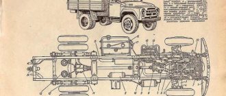
Removing the power unit
To provide better access to the vehicle components from below (when removing the power unit), it is recommended to install the vehicle on an inspection hole, above which there is a lifting device.
The weight of the assembled power unit without refueling is 640 kg, and therefore to remove it it is necessary to have a lifting device with a lifting capacity of at least 1 ton; the height to the hook must be at least 2 m. Before removing the power unit from the vehicle, it is necessary to drain the water from the cooling system; it is also advisable to drain the lubricant from the engine crankcases and gearbox. Water is drained through three drain taps. When disassembling, it is recommended to place small parts in separate containers, and when disconnecting wires from electrical equipment, screw the screws and nuts by hand into their place.
Before removing the power unit, the following preparatory work must be performed. Remove the hatch cover of the battery socket and release the positive terminal of the battery, remove the starter wire, and for the ZIL-131 car, turn off the ground using the switch.
Raise the engine hood and disconnect the wires from the instruments and adapter blocks, remove the cover and rotor from the distributor-breaker.
Loosen the screws of the clamps and remove the water and oil radiator hoses. Remove the pipeline with heater hoses.
Disconnect the blinds drive cable and remove it together with the sheath from the hole in the front wall of the cabin.
Loosen and remove radiator trim.
Unscrew the radiator mounting nut.
remove the radiator manually or using the K3-0355 tool (Fig. 1, a), remove the rubber pads with the spacer sleeve.
Disconnect the carburetor drive and check: the foot drive linkage, the manual throttle cable and the manual choke cable.
Disconnect and remove: the pipeline that discharges compressed air from the compressor; pressure regulator pipeline; pipeline supplying fuel to the fuel pump.
Disconnect the high and low pressure hoses from the power steering pump housing.
Disconnect the steering gear drive and remove the steering driveshaft.
Disconnect the exhaust pipes of the muffler from the exhaust pipe by bending the lock washers and unscrewing the nuts.
Remove the cabin floor hatch cover by unscrewing the fastening bolts.
Remove the gearbox lever housing with the gasket as an assembly with the lever by unscrewing the housing mounting bolts.
Close the hole in the gearbox cover with a cardboard cover, securing it with two bolts.
Disconnect the speedometer drive by unscrewing the clamping nut of the fitting.
Disconnect the foot brake drive by disconnecting the rod from the pedal lever.
Disconnect the hand brake drive acting on the trailer brakes.
Remove the handbrake lever from the gearbox by unscrewing its mounting bolts.
Disconnect the propeller shaft from the handbrake drum by unscrewing the nuts securing it.
Disconnect the clutch release drive by disconnecting the rod and pedal lever.
On a ZIL-131 car, disconnect the driveshaft from the flange of the gearbox driven shaft.
Disconnect the transfer case drive and control lever.
If the vehicle has a winch, disconnect the driveshaft of the power take-off, remove the cover and drive lever.
Loosen the bolts securing the front mount and the two rear engine mounts, as well as the tie rod mount.
Hook the lifting device (Fig. 1, b) onto the engine brackets and carefully, lifting and moving forward, remove the power unit from the car.
The removed power unit from the vehicle is installed on a special trolley to transport it to the disassembly site.
Source
Engine mechanisms
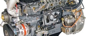
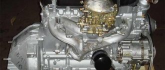
The ZIL-130 engine is a four-stroke unit with eight cylinders arranged in a V-shape at an angle of 90˚. The engine is carburetor. The internal combustion engine uses a water cooling system, the circulation in the system is forced.
Rice. 1. Engine ZIL-130
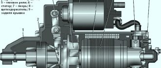
Rice. 2. Engine mount: a – front support; b – rear support; 1 – protective cap; 2 – front support mounting bolt; 3 – front support bracket; 4 and 12 – engine mounting bolts; 5 – front cover of the cylinder block; 6 – upper cushion of the front support; 7 – lower cushion of the front support; 8 – washer; 9 – spacer sleeve; 10 – frame cross member; 11 – clutch housing; 13 – rear support mounting bolt; 14 – cover; 15 – rear support bracket; 16 – shoe; 17 – rear support cushion; 18 – adjusting shim
The cylinder block is cast from cast iron, the insert liners ("wet" liners are used) are also made of cast iron, which includes ferrite compounds. In the upper part of the BC there is an insert made of special cast iron. This part of the block wears out faster. To extend its service life, thin-walled acid-resistant sleeves (material – cast iron) are pressed into it. To ensure sealing of the liner in its upper part, an asbestos-steel gasket is used in the cylinder head. The gasket helps to clamp the liner collar between the block and the cylinder head. Two rubber rings provide a seal to the bottom of the sleeve.
The material for the manufacture of the cylinder head with insert seats and valve guides is aluminum alloy. An asbestos-steel gasket is placed between the block and the cylinder head. Each head is fastened to the block with bolts (17 in total); the holes for them are pre-faceted. Of the total number of mounting bolts for each cylinder head, four serve to fix the rocker arm axis and are simultaneously used to fasten the cylinder head.
To tighten the fasteners and control the tightening force, use a torque wrench. This is due to the difference in the expansion of the heated material from which the block head (aluminum) and fasteners (steel) are made. Tightening the cylinder head mounting bolts is done with the engine cold. This is done because the cylinder head tightening will increase or decrease depending on whether the temperature of the internal combustion engine increases or decreases. At engine temperature:
After the cylinder head mounting bolts are tightened, it is necessary to check and adjust the valve clearances, if the need arises. The mounting bolts of the exhaust gas pipelines are tightened together with the tightening of the cylinder head mounting bolts.
In Fig. Figure 5 shows how the cylinder head mounting bolts are tightened in two stages:
Rice. 5. Sequence of tightening the cylinder head bolts
This way you can ensure that the cylinder head planes are completely adjacent to the block. First, you should remove deposits from the water holes of the combustion chamber, BC and cylinder head, then start changing the gaskets. The cylinder head cover gasket has a grooved surface. For proper installation, the grooved surface must face the cylinder head cover. It is necessary to adjust the force for tightening the cylinder head cover fastening nuts - it should be from 0.5 to 0.6 kgf∙m (from 5 to 6 N∙m). It is necessary to tighten evenly.
The material of the pistons is aluminum alloy, which is coated with tin. It is necessary to monitor the compliance of the liner and piston. The probe tape, whose dimensions are 200x10x0.08 mm, and the piston are recessed into the cylinder. The tape is pulled through with force. The tape is clamped in the cylinder between its wall and the piston, and force must be applied to release it. The force applied to pull the tape must be measured - its value should be from 2 to 3.5 kgf (20-35 N).
Fixation of the floating piston pins in the piston is done using two retaining rings. The manufacturing precision of piston pins is very high. The fingers are selected to the connecting rods and pistons. The fingers are sorted into different groups based on their outer diameter (there are four in total). The external diameter is used as a criterion for sorting. In order to indicate that a part belongs to a certain group, the corresponding designation is applied to it with paint. Place of application of this designation:
During assembly, only parts from the same group can be used. To do this, each of them must be marked with a mark indicating that it belongs to this group. It should be remembered that scoring may appear on the mating surfaces of the parts. To prevent this, the pistons are first placed in oil and then heated to 55°C. Only after this do they begin to assemble the piston and pin.
rings installed on each piston is four, of which one is oil scraper and three are compression. The difference between the two upper compression rings is the chrome coating applied. Chrome plating is applied to the outer cylindrical surface.
The lower compression ring has a conical shape. The base of the cone points downwards. Compression rings are installed correctly if the groove on their inner cylindrical surface faces upward (Fig. 6). The oil scraper ring is composed of two steel rings, flat in shape, as well as two expanders, axial and radial.
Rice. 6. Piston with connecting rod: 1 – annular disk of the oil scraper ring; 2 – axial expander; 3 – radial expander; 4 – lower and middle compression rings; 5 – upper compression ring; 6 – retaining ring; 7 – piston pin; 8 – arrow on the piston bottom; 9 – piston; 10 – connecting rod; 11 – mark on the connecting rod rod; 12 – boss on the connecting rod cover
When installing the piston, flat-shaped steel rings are installed in such a way that the locks of the annular disks are at an angle of 180° to one another. The angle at which the locks of both expanders are installed in relation to the locks of the steel disks should be 120°.
With this shape of the piston rings, it is possible to achieve optimal distribution of the ring pressure that it exerts on the walls of the liner. This helps to increase the working life of the part and makes it possible to change rings, subject to timely maintenance, only when carrying out a major overhaul of the internal combustion engine. Before replacing the piston rings, the oil consumption is checked for waste, for which external oil leaks are eliminated, the crankcase ventilation system filter is washed, and deposits on the valve are removed. This must be done before deciding to overhaul the internal combustion engine. If there are no sufficient grounds for making a decision to replace the piston rings, it cannot be carried out - this can lead to a decrease in the service life of the internal combustion engine.
The need to replace piston rings or send the internal combustion engine for overhaul is determined only after diagnostics using special equipment.
The service life of the ZIL-310 internal combustion engine can be extended if:
The connecting rods are made of steel and have an I-beam cross-section. A bronze bushing is pressed into the upper head of the part. Inserts are pressed into the bottom. The liners are made of an alloy of aluminum and tin (they are called steel-aluminum), they are thin-walled.
Precision in the production of liners further eliminates the need for precision leveling of their surface (scraping) and joints, as well as the use of gaskets. Moreover, such actions are prohibited.
When installing the piston and connecting rod, the following rules must be observed:
The force for tightening the connecting rod bolt nuts using a torque wrench should be from 5.6 to 6.2 kgf∙m (from 56 to 62 N∙m). The required force is checked and the nuts are additionally tightened each time the sump housing is removed.
The crankshaft is five-bearing, there are hardened journals. The part is made of steel. The crankshaft has channels for lubrication (Fig. 7). The cavities provided for oil purification are closed by plugs. The plugs have an internal hex key that is used for unscrewing. The force for tightening them should be at least 3 kgf∙m (30 N∙m). The permissible size of the protrusion of the part above the crankshaft surface is the height of the chamfer. Cavities are cleaned during repair work. Cleaning should also be carried out when replacing connecting rod and main bearings and when the mileage has exceeded 100 thousand km.
Rice. 7. Crankshaft: 1 – counterweight; 2 – plug; 3 – cavity for centrifugal oil purification
There is interchangeability of main bearing shells on all supports. This does not apply only to the rear support.
The material from which the flywheel is cast iron. It is attached to the crankshaft flange with 6 bolts. The flywheel has a toothed ring made of steel. With its help, the internal combustion engine is started from the starter. The offset of one of the mounting holes of the part is 2° - this must be taken into account when assembling with the crankshaft. The flywheel mounting nuts must be tightened to the crankshaft flange with the same force. The flywheel mounting bolts must be well secured.
The camshaft is made of steel. There are hardened cams and ignition distributor drive gear. The camshaft is five-bearing. Bushings are pressed into the supports (they are made of bimetallic tape). The camshaft is driven by two gears. The installation of the crankshaft and camshaft wheels is considered correct when the marks are located on a straight line that connects the centers of these wheels (Fig. 8).
Rice. 8. Position of marks on gears when setting valve timing
The material for the manufacture of valves is heat-resistant steel. The valves are located in a single row in the cylinder head at an angle relative to the cylinder axis. The valves are driven from the camshaft through rods, pushers and rocker arms. The valve seats have a working chamfer. The angle of the working chamfer at the intake valve is 30°, at the exhaust valve – 45°.
To increase the service life of the exhaust valves, a forced turning mechanism is used (Fig. 9).
If a knock occurs in the valve mechanism, they are checked. If necessary, adjust the gaps between the valves and rocker arms. The established clearance limits for valves, both intake and exhaust, are from 0.25 to 0.30 mm. The gaps are adjusted using a special adjusting screw with a lock nut. The adjusting screw is located in the short arm of the rocker arm. Adjustments can only be made when the engine has cooled down.
The adjustment is made as follows: set the piston of the first cylinder to the top dead center of the compression stroke. This point is also called TDC. It is necessary to install the hole on the crankshaft pulley under the TDC mark on the ignition timing indicator.
Having installed the piston of the first cylinder and the hole on the crankshaft pulley in this position, the cylinder valve clearances are adjusted:
| intake and exhaust cylinder 1 | exhaust cylinder 4 |
| exhaust cylinder 2 | exhaust cylinder 5 |
| intake cylinder 3 | intake cylinder 7 |
| intake cylinder 6 |
The remaining valves are adjusted by rotating the crankshaft 360°.
Malfunctions that may appear if the internal combustion engine operates for a long time with incorrectly adjusted clearances:
When disassembling an engine whose mileage exceeds 70,000 km, it is mandatory to check the condition of the return springs and balls of the mechanism for turning the exhaust valve.
When wear appears on the coils of the spring, you need to turn the part with the worn part down. It is necessary to correctly assemble the mechanism for turning the valves - in the selected direction of rotation, the spring is installed behind the ball.
Valve pushers (they are hollow) are made of steel. Cast iron is fused to the end of the part - this increases the reliability of the cam-pusher pair. A hole is drilled in the pusher, at the bottom of the part, which is used for lubrication.
Exhaust pipelines are made of cast iron. They are located on each side of the BC.
Sequence of actions and necessary tools
Before starting work, you should make sure that the mating surfaces are free of contamination. If parts have previously been in use, they should be cleaned using special tools, solvents and detergents. The head must be checked for flatness and, if necessary, ground. After that:
To develop the necessary force without damaging critical parts, it is recommended to use:
Pull smoothly, ensuring uniform tightening torque of the ZIL-130 engine. Jerks and shock loads are unacceptable! It is advisable to perform all operations by mounting the motor on a special stand. But it is possible, if there is no other way out, to carry out repairs without removing the power unit from the car. For convenience, it makes sense to remove the hood cover.
Reasons for repairs
Before we begin to directly consider the issue of carrying out major repairs, it is worth considering for what reasons it is being carried out. So, why does the ZIL engine fail:
- Wear of main elements, such as the crankshaft or power unit cylinders. This is related to work and resource development.
- Burnout of the piston mechanism due to exposure to time, as well as the use of low-quality fuel.
- Mechanical damage to the cylinder head and block. Presence of cracks and wear on the seals.