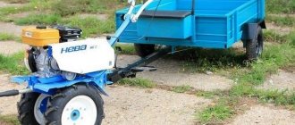
How to make a front drive axle on a T 25 with your own hands video
Is it possible to install a front axle (drive) from a T40 to a T25?
This question has been bothering me for a long time, does anyone know where the cardan on the front axle on the T30 comes from?
aslanbi in T-30 front axle cord drive from rear axle differential
Yaugen, that is, you can’t connect a cardan to a regular T25 box? I was thinking how it’s connected to a T40. I want to hook up a front loader on a T25, so I think without a front end it will be useful? I remember once I borrowed an MTZ80 from a friend with a KUN to load manure in the garden, it skidded more than it loaded.
Asianbi depending on what year the box is in the newer boxes the hatch is made from below in a suit with such a box it won’t be too difficult to install the front axle as for the front axle, I have it on the T-25 I load manure with gravel with it I clean the snow and the front axle would not hurt but for Last night I want to change the front wheels, put wider ones and also put the rear ones with sk-4, if all this does not give the desired result, then I will also install the front axle, but the drive on it will be hydraulic
I have a 93 Yaugen. HTZ 25f, I haven’t seen a box with a hatch yet, but can’t you connect the cardan to the shaft that comes out from the side of the box where the pump is located? I wonder if the bridge will withstand a UAZ?
aslanbi we think equally this is pleasing since you propose, i.e., in principle, it is possible to connect the cardan to the side PTO, but you need to make a disconnecting coupling. Since the revolutions of the front and rear wheels will differ quite greatly and you will only have to engage the axle in heavy mud, since on a hard surface the side shaft may break or the shaft may twist. In principle, the UAZ Bridge will survive, but only in the version without a frontal bridge. I saw on the T-16 there was a front UAZ axle, the cordan was connected directly to the power take-off shaft and there was nothing going on. Personally, I will install 2 hydraulic pumps: 1 on the side PTO; the second on the axle; hydraulics will soften the difference in speed of the front and rear wheels; personally, I am inclined to use the MTZ or T40 axle
Yaugen, in principle, your idea is good, but I really don’t like the front ends, especially from the T40, there’s a lot of metal, if it was possible to cut it down, I would put it from the 66th, the MTZ one is probably expensive and the landing will probably be high, but what kind of hydraulic motors can be installed?
aslanbi 66th the bridge is very easy to cut, but it stops one distance between the bridge and the ground will turn out to be small and there is nothing to do with a stock landing in the forest in the T-30 there is a T-40 bridge and so that the tractor stands horizontally level, the factories have the side panels thrown over it turns out quite high and with It is not convenient to work with a frotal when it is lowered; the installation rests on the wheels when turning them; therefore, you will have to put the wheels on 15-16; the hydraulic motors will come from German equipment
Yaugen bought a low-slung tractor from me and I drive it and I don’t want to lift it from the front loads to the ground about 30 cm. On the 66th I think no less, well, I don’t know, I haven’t had to drive through swamps yet, but how to cut the axle? I roughly understand the rear one but the front one doesn't.
aslanbi here is the drive for the front axle in the T-30 Files: dsci0074.jpg dsci0073.jpg
Jaugen Thanks for the photos! What sizes are hydraulic motors? Where can they be attached to the bottom? I thought too and came to the conclusion that a hydraulic drive would be better, you don’t always need a front end.
djenym on the T-30u there were two types of bridges on the first models the bridge was shol with the T-40 on the new models the bridge is somewhat similar to the bridge from the 320 Belarusian I can’t upload a photo of the bridge yet because the tractor is being repaired, the front axle will be installed now I don’t know but the owner of the tractor wants a new model because the bridge said about the T-40 that it’s too tough for a tractor and it’s a pile of metal
djenm good evening, if you want to change the gearbox body, then you will have to change all the gears, as well as the clutch and basket, since the power take-off shaft in the T-30 is independent, the semi-frame is just as tubular as the T-25, but the axle mount is made differently, once the tractor appears, I’ll do it detailed photo of all components, the tires on the T-30 are wider than those on the T-25, the height is the same, I would like to ask if the cross-country ability of the tractor on these wheels has increased compared to the original T-25 tires and is it worth installing them? I would also like to see a photo of how you put them on secured to the hubs
Djenym good evening, can you tell me more about the lift? I’m interested in the lifting capacity and the height of the lift, but I once asked on the forum about the possibility of installing it on the T-25, so people started swearing at it
Djenym thanks for the answer according to this scheme, I wanted to put as for the front axle the easiest way to create a front axle for the T-25 is to install a UAZ axle and connect a hydromator to it. and connect the bridge between the two with a fork coupling which will allow the hydraulic pump to be turned on and off from the front axle. connect the hydraulic pump to the distributor
Yaugen, I have not dealt with the hydraulic motor, but it seems to me that when the front end is turned off, the hydraulic motor should spin from the wheels and will interfere? mail.ru is there, send it or write
I have a Jaugen loader that looks like this Files: 41278253_1_0.jpg
djenym thank you for the photo of this one and they only offer me the lift itself, which is massive. As for the hydraulic pumps, I had to take them off. I came across a pretty good thing, now what concerns the installation of it for the bridge when you drive along the road where the front axle is not needed, the hydraulic pump will be disconnected by the clutch and there will be no resistance to the bridge will be when the tractor is working in the mud, connect the clutch and distributor to the floating position, as soon as the tractor starts to sit down, connect the distributor and, depending on where you need it, forward and back, press the corresponding button on the distributor
djenym thank you for the photo of this one and they only offer me the lift itself, which is massive. As for the hydraulic pumps, I had to take them off. I came across a pretty good thing, now what concerns the installation of it for the bridge when you drive along the road where the front axle is not needed, the hydraulic pump will be disconnected by the clutch and there will be no resistance to the bridge will be when the tractor is working in the mud, connect the clutch and distributor to the floating position, as soon as the tractor starts to sit down, connect the distributor and, depending on where you need it, forward and back, press the corresponding button on the distributor
I'm terribly sorry, I just didn't understand about the clutch
I apologize for interfering. Dear Colleagues, you have made me very interested in the hydraulic drive of the front axle. I have a YuMZ-6, it’s unrealistic to put a front end on it, but my tractor was an Excavator and on the left side there is a side PTO, and a booster one at that! It used to drive a powerful hydraulic pump for excavator equipment. But you can install a suitable hydraulic pump and a front axle from a T-40 or MTZ-ovsky and drive it with a hydraulic motor. I understand the theory, but in practice I have had no experience with hydraulic motors. But in this way it is possible to install the front end on YuMZ. True, you still need a distributor for forward-reverse gear.
I apologize for interfering. Dear Colleagues, you have made me very interested in the hydraulic drive of the front axle. I have a YuMZ-6, it’s unrealistic to put a front end on it, but my tractor was an Excavator and on the left side there is a side PTO, and a booster one at that! It used to drive a powerful hydraulic pump for excavator equipment. But you can install a suitable hydraulic pump and a front axle from a T-40 or MTZ-ovsky and drive it with a hydraulic motor. I understand the theory, but in practice I have had no experience with hydraulic motors. But in this way it is possible to install the front end on YuMZ. True, you still need a distributor for forward-reverse gear.
djenm good evening, if you want to change the gearbox body, then you will have to change all the gears, as well as the clutch and basket, since the power take-off shaft in the T-30 is independent, the semi-frame is just as tubular as the T-25, but the axle mount is made differently, once the tractor appears, I’ll do it detailed photo of all components, the tires on the T-30 are wider than those on the T-25, the height is the same, I would like to ask if the cross-country ability of the tractor on these wheels has increased compared to the original T-25 tires and is it worth installing them? I would also like to see a photo of how you put them on secured to the hubs
I apologize for interfering. Dear Colleagues, you have made me very interested in the hydraulic drive of the front axle. I have a YuMZ-6, it’s unrealistic to put a front end on it, but my tractor was an Excavator and on the left side there is a side PTO, and a booster one at that! It used to drive a powerful hydraulic pump for excavator equipment. But you can install a suitable hydraulic pump and a front axle from a T-40 or MTZ-ovsky and drive it with a hydraulic motor. I understand the theory, but in practice I have had no experience with hydraulic motors. But in this way it is possible to install the front end on YuMZ. True, you still need a distributor for forward-reverse gear.
Repair of front axles and drive axles of tractors of traction class 1.4.
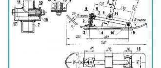
Front axles The gap in the ball joint of the steering rod, the runout of the wheel when moving in a straight line indicate wear on the working surfaces of the joint. The rod is compressed from the conical surface of the finger using a special device
(Fig. 80). The pin is replaced when the ball surface is worn to a size of 31.8 mm, and the liners are replaced to a size of more than 32.4 mm. Sharp shocks and impacts transmitted to the semi-frame of the MTZ-80 and T-40 tractors when driving over uneven surfaces are a consequence of breakage or loss of elasticity of the suspension springs. To replace the springs, compress the rotary arm, remove the axle and unscrew the fastening of the lower bushing of the rotary axle. Creaking noises when the wheel rotates or its beating indicate wear or destruction of the hub bearings or loosening of the tapered bearing nuts. When an external inspection fails to identify the cause of the malfunction, measure the axial clearance in the hub bearings
(Fig. 81). If it exceeds 0.5 mm, then it is adjusted. Unscrew the castle nut, tighten it as far as it will go and unscrew it to one side (20...30°). After this, the wheel should turn freely, without jamming, with a little hand effort. If the wheel sticks or rotates unevenly, the hub is disassembled. When adjusting the bearing clearance, it may be discovered that the castle nut has become loose; in this case, check the condition of the tapered bearings. Unscrew the nut and compress the hub with a special puller. During the inspection, they move the bearing races in the axial direction and try to rotate them in their seats. If chips or breakages are detected, as well as if there is axial movement or rotation of the races in the seats, the bearings are replaced. Knocks in the steering knuckles, “yaw” of the tractor when driving in a straight line indicate wear of the axle bushings. The axle bushings are replaced when the inner surface is worn to the following size: for the MTZ-80 tractor - lower - 50.5 mm, upper - 38.6 mm; at YuMZ - both bushings - 50.9; for T-40 and T-25 - both bushings - 35.5; for the T-16M, both bushings are 45.5 mm. After disassembling and reassembling the front axle, and also if the tractor “steers” to the side when driving on a flat road or there is increased wear on the rubber of the front wheels, check and adjust the toe-in of the front wheels. To do this, turn the steering wheel until it stops in one direction and move it in the opposite direction until it stops, counting the number of turns of the steering wheel. Then return the steering wheel to the middle position, turning it half the previously counted revolutions. Install the KI-650 ruler with its tips into the tire next to the wheel rim at the level of the axle, and the ruler arrow at the “0” scale mark. Next, rotating both wheels with the front axle jacked up, move the ruler to the front position, also at the level of the axle. Read the readings of the ruler on the scale. If the result goes beyond 6...12 mm, the convergence is adjusted by increasing or decreasing the length of the transverse rods. In case of cracks in the front axle housing or extreme wear of the swing axis, the front axle is removed as an assembly and replaced with a new one. To remove and install the swing axis and its bushings, use special pullers and devices
(Fig. 82). The swing axis is replaced with landing dimensions less than: for the MTZ-80 tractor - 49.9 mm; T-40 and T-16M -40.1; T-25 -45.1; at YuMZ - 49.5 mm.
T-25 with UAZ (3151) military bridge.
So I decided to install a UAZ front axle for my T-25. I dismantled the bridge to shorten the right stocking. To press out the stocking, you need to drill out the electric rivets. We were able to drill it out only with homemade Pobedit drills. I'm thinking of changing the wheels from T-25 to 16*. tires 7.50L-16 with an outer diameter of 792mm. What is your offer? Let's discuss this topic together!
I'm thinking of changing the wheels from T-25 to 16*. tires 7.50L-16
The wheel rims are small, it seems to me that the tractor will nod and the clearance is small, the rims are needed for 20* i.e. from T-40. By the way, such discs are installed on UAZ vehicles.
What is your offer? Let's discuss this topic together
How will the front axle be driven?
I will make the axle drive approximately like the T-30. Files: img_0001.jpg
I will make the axle drive approximately like the T-30
Is there a hatch in the box? I have a monolith
If there is no hatch, I would like to hear your thoughts.
There is no hatch. There will be a grinder and a hatch!
There is no hatch. There will be a grinder and a hatch!
Well, how to connect, I’m afraid you’ll suffer, but it’s of little use
Thank you for the moral support! Justify why it’s tormenting and why it’s of little use? I don’t see anything scary yet!
Justify why it’s tormenting and why it’s of little use? I don’t see anything scary yet!
One of two things: 1. Either you imagine in every detail how you will do this, you have calculated everything, and it does not cause you any difficulties (I take my hat off to you). 2. Either you don’t fully understand what you’ll have to face.
In any case, the process and the result will be very interesting.
Here I shortened the bridge stocking. When installing T_25 discs, the size of the stake will be 120cm. Files: foto0847.jpg
Thank you for the moral support! Justify why it’s tormenting and why it’s of little use? I don’t see anything scary yet!
Hello, I’m also thinking about the topic of warriors instead of the front axle on the T-25, a question for experts: should I make a drive from the side PTO? through the industrial support, respectively, with an overrunning clutch (with the possibility of blocking) Alexander Panteleevich 63 for you a couple of questions, why are you cutting the track to 1.2, because the UAZ has something like 1.4 and the wheels are from the T-25, why redo it, because there is a UAZ wheel with 16″
“Brevity is the sister of talent” A.P. Chekhov
to make a drive from the side PTO? through the industrial support, respectively, with the overrunning clutch (with the possibility of blocking)
IMHO it is too difficult for full functionality: 1 Use it only in one gear or install an additional gearbox (variator). 2 The side shaft spins even when the gear is not engaged, you need to install a coupling so that the front end is connected only when the gear is engaged (I read somewhere that they install an electric coupling from a lathe and a gear shift sensor). 3 It should be taken into account that slow transmission can also be activated at Z.H.
If you do all this with manual control, then you need to learn like a pilot. You can, of course, assign these tasks to electronics, then it will also be almost an airplane. But if you do everything just to manually turn it on briefly, I think there’s no point. IMHO it should be done like in an industrial setting. on tractors, it is desirable that the front row be rowed back, and the center diff with locking.
Melnikov Lexa from the side PTO can be made for only one gear, and if you move to another, then such axle will have to be disconnected. The gearbox of the GAZ-66 axle is mounted, it has an automatic lock, it is certainly larger in size, but can be used as a basis. I make the track 1.2 since my rear is also 1.2, Stocking only hit one. I will install wheels from T_25. With the wheel protection I get a track width of 1.2, but on the UAZ wheels I got 1.12.
Source
T-25 with UAZ (3151) military bridge.
So I decided to install a UAZ front axle for my T-25. I dismantled the bridge to shorten the right stocking. To press out the stocking, you need to drill out the electric rivets. We were able to drill it out only with homemade Pobedit drills. I'm thinking of changing the wheels from T-25 to 16*. tires 7.50L-16 with an outer diameter of 792mm. What is your offer? Let's discuss this topic together! I'm thinking of changing the wheels from T-25 to 16*. tires 7.50L-16
The wheel rims are small, it seems to me that the tractor will nod and the clearance is small, the rims are needed for 20* i.e. from T-40. By the way, such discs are installed on UAZ vehicles.
What is your offer? Let's discuss this topic together
How will the front axle be driven?
Good morning everybody! The UAZ (3151) has a ground clearance of 300mm on its tires. Tire size 8.40-15, approximately 760mm. — diameter. Do you have technical data for tires suitable in size for this bridge? Files: img.jpg
I will make the axle drive approximately like the T-30. Files: img_0001.jpg
I will make the axle drive approximately like the T-30
Is there a hatch in the box? I have a monolith
If there is no hatch, I would like to hear your thoughts.
There is no hatch. There will be a grinder and a hatch!
There is no hatch. There will be a grinder and a hatch!
Well, how to connect, I’m afraid you’ll suffer, but it’s of little use
Thank you for the moral support! Justify why it’s tormenting and why it’s of little use? I don’t see anything scary yet!
Justify why it’s tormenting and why it’s of little use? I don’t see anything scary yet!
One of two things: 1. Either you imagine in every detail how you will do this, you have calculated everything, and it does not cause you any difficulties (I take my hat off to you). 2. Either you don’t fully understand what you’ll have to face.
In any case, the process and the result will be very interesting.
Here I shortened the bridge stocking. When installing T_25 discs, the size of the stake will be 120cm. Files: foto0847.jpg
Thank you for the moral support! Justify why it’s tormenting and why it’s of little use? I don’t see anything scary yet!
Hello, I’m also thinking about the topic of warriors instead of the front axle on the T-25, a question for experts: should I make a drive from the side PTO? through the industrial support, respectively, with an overrunning clutch (with the possibility of blocking) Alexander Panteleevich 63 for you a couple of questions, why are you cutting the track to 1.2, because the UAZ has something like 1.4 and the wheels are from the T-25, why redo it, because there is a UAZ wheel with 16″
to make a drive from the side PTO? through the industrial support, respectively, with the overrunning clutch (with the possibility of blocking)
IMHO it is too difficult for full functionality: 1 Use it only in one gear or install an additional gearbox (variator). 2 The side shaft spins even when the gear is not engaged, you need to install a coupling so that the front end is connected only when the gear is engaged (I read somewhere that they install an electric coupling from a lathe and a gear shift sensor). 3 It should be taken into account that slow transmission can also be activated at Z.H.
Front axle of the T-25 tractor
The complex of units and mechanical components of the tractor chassis that connect the wheels located on the same axis and serve as reliable support for the front part is called the front axle.
By means of a suspension, the bridge is attached to the frame and supporting body.
Its main purpose is to interact with the steering control of the T-25 tractor, which ensures turns, while at the same time being a reliable front support. It consists of steering axles and knuckles, with many levers and a steering linkage, and of course the wheel hubs and balancer.
Operating principle and diagram of the T-25 front axle
For a complete understanding, we ask you to familiarize yourself with the diagram below.
The front axle balancer is made of steel and in its middle part there are bosses in which hardened bushings are located. The main axis passes through them, which is located in the frontal part of the half-frame fastening; it is fastened using tightening bolts with a conical tail. The front axle of the axle is used as the rolling center. With the help of an articulated joint, the axle can adapt to various ground unevenness, regardless of its frame and rear wheels. At the very top of the balancer there are also bosses; the half-frame mount rests against them, which limits the rolling angles.
The steering knuckles are fixed in the split ends of the balancer using tie bolts. To adjust the track width of the front wheels, each knuckle is equipped with four holes. Depending on which hole the pin is inserted into, the track width of the front axle of the T-25 tractor depends.
The front axle cam is attached to the lower flange, made in the shape of a rectangle. The axle itself is secured with two studs and bolts.
The design of the front axle of the T-25 tractor includes a thrust ball bearing, which is installed in the bore of the steering knuckle.
The upper ring of the bearing is mounted in the bore, and its lower boundary rests against the shoulder of the fist passing through the spacer ring.
Important! The bearing ring rotates along with the axle when the tractor makes a turn.
For additional protection from external contamination, a felt gland is used.
The front wheel rotation limiter is welded to the lower part of the steering knuckle. The thrust knuckle bearing is lubricated using the attached oiler.
The steering linkage consists of a set of levers and a transverse rod, used to turn the front wheels to the desired angle.
Transverse rod - a longitudinal pipe with ends in which rods are installed, tightened with bolts. Each rod consists of four flats. They serve to completely fix the position of the rod, which corresponds to the established track.
Diagram and principle of operation of the front wheel hub
First, let's look at the diagram of the T-25 tractor hub.
Its rotation is carried out using two tapered roller bearings, which are installed in the cylindrical part of the axis. There is a threaded hole in the hub, which serves to lubricate the bearings located in the front wheels and is closed with a threaded plug. The outer part is closed with a molded lid. As you can see, the hub diagram is relatively not difficult to understand, but if you still have questions, we will be happy to answer them in the comments at the end of the article. To enlarge the diagram, simply click on it with the mouse.
Front axle joint tractor T-25
The front axle system uses a ball joint, which consists of springs, a pin and a cover. Let's look at its diagram with a description.
Using castle nuts, the conical tail of the pin is tightened into the conical hole of the lever. The surfaces of the ball bearings and pins are hardened.
To ensure that there is no play in the connections during natural wear of the liners, a spring is used that presses the upper part of the liner to the ball surface.
content .. 81 82 88 ..FRONT AXLE OF TRACTOR T-25
The running system of the T-25 tractor consists of a front axle, front guide wheels and rear drive wheels with low-pressure pneumatic tires. To use the tractor for inter-row cultivation of row crops with different row spacings, the track of the driving wheels is adjusted from 1100 to 1500 mm with an interval of 100 mm, and the track of the front wheels is within the range of 1200–1400 mm.
The front axle of the tractor consists of a transverse balancer, steering knuckles with rotary axles, front wheel hubs, levers and steering linkage rods.
The cast steel balancer 16 (Fig. 66) has bosses in the middle part into which steel bushings 1, cemented and hardened to high hardness, are pressed. Axle 2 freely passes through the bushings, secured in the front bracket of the semi-frame with bolt 3 with a tapered shank and a coupling bolt 21. Axle 2 serves as the swing axis of the front axle. The articulated joint allows the front wheel axle to adapt to uneven ground conditions regardless of the position of the tractor frame and its rear wheels.
There is a flat at the front end of the axle, which facilitates the alignment of the tapered hole in the axle for the locking bolt 3 with the threaded hole in the front bracket of the half-frame. The threaded hole at the end is used to press out the axle when dismantling the front axle. The hard surfaces of the bushings and axle can withstand very harsh conditions and do not require lubrication.
To limit the swing angle of the balancer, lugs are made in its upper part, with which the balancer rests against the half-frame bracket.
The steering knuckles 6 are clamped in the split ends of the balancer with coupling bolts 15. The position of the knuckles is fixed by pins 23, which pass through the holes in the balancer and the knuckles. The pins are welded to strips 22, bolted to the balancer. To adjust the track of the front wheels, each knuckle has four holes; the size of the front axle track depends on which of the holes pin 23 goes into.
In the protruding inclined part of the steering knuckle, two steel cemented and hardened bushings are pressed into which axle 4 rotates. The upper cylindrical end of the axle with a keyway and a threaded hole at the end comes out of the steering knuckle and is used to fasten the steering arms and brackets for the front wings. A single-arm lever 14 is attached to the steering knuckle axis on the right side of the tractor with a tightening bolt and a key, and a double-arm lever 18 is attached to the left one.
The flange of the front wheel axle 13 is attached to the lower rectangular flange of the steering knuckle axle. The axle is secured by two bolts 10 and two special studs 12. Two locating pins 11 unload the bolts and studs and determine the relative position of the wheel axis and the steering knuckle axis during readjustments of the tractor. In Fig. 66 at the top, the solid lines show the installation of the front wheel axle in the high setting of the tractor. By turning the axle 180° upward (shown by thin lines) while simultaneously turning the final drives 90° back or forward, a low adjustment is obtained, while the tractor's ground clearance is reduced by 207 mm. In Fig. 66 at the bottom left shows the installation of the axis in the main setup.
The bolts and studs for fastening the axles are locked with locking washers, the ends of which are bent at the edges of the bolt heads and hexagons made in the middle part of the studs. The lower bracket of the front wheel fenders is attached to the outer threaded ends of the studs.
A ball thrust bearing 7 is installed in the bore of the steering knuckle. The upper bearing ring is pressed into the bore, and the lower ring rests through the spacer ring 8 against the shoulder of the knuckle axle and, when the tractor turns, rotates along with the axle. The felt seal protects the bearing from dust and dirt. Through thrust bearings, the front part of the tractor rests on the axles of the steering knuckles and the front wheels of the tractor connected to them.
A limiter 9 for turning the front wheels is welded to the bottom of the right steering knuckle, into which the projections of the axle flange rest. To lubricate the bearing, an oiler is installed in the thrust cam.
Rice. 66. Front axle:
1 — front axle balancer bushing; 2 - swing axis of the balancer; 3 - lock bolt; 4 — steering knuckle axis; 5 — bushing of the steering knuckle axis; 6 — steering knuckle; 7 — ball thrust bearing; 8 - spacer ring; 9 — rotation limiter; 10 — front wheel axle mounting bolt; 11—locating pin; 12 — stud securing the front wheel axle; 18 — front wheel axle; 14 — right swing arm; 15 — balancer coupling bolt; 16 — front axle balancer; 17 — longitudinal steering rod; 18 — left swing arm; 19 — transverse rod; 20 — transverse thrust; 21 — coupling bolt of the swing axis; 22 — bar; 23 - pin; 24 - ball joint; 25 — front wheel hub
content .. 81 82 88 ..
Tractor T-25 - technical characteristics, repair, design
The T 25 tractor came off the assembly line just at a time when the production of agricultural machinery in the USSR was rapidly increasing its turnover.
Farmers of that time felt an urgent need to automate manual labor precisely in those areas where a large unit could not help.
Landowners needed a small but fairly reliable machine, which the T 25 tractor performed perfectly well.
Tractor technical characteristics
The T 25 tractor is a universal wheeled unit. It has gained its popularity not only because of its reliability and ability to operate in various conditions with almost any type of hitch, but also due to its good technical characteristics. Among them are:
The T 25 tractor has small dimensions. The length of the unit is 3.18 and the width is 1.47 m. The height of the machine, including the cabin, is 2.47 m. Modest overall dimensions make the T 25 tractor an indispensable assistant in small areas, ranging from several hundred to 2-3 hectares.
The unit can be confidently used in conjunction with a potato digger, harrows, and plows. The T25 tractor works effectively with a potato hiller; if necessary, the unit can be operated together with a hiller.
To transport cargo, the tractor owner can attach a homemade trailer or a single-axle cart to the unit.
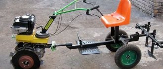
Often, when cultivating soil, farmers install special “hedgehogs” on the tractor, which help cultivate hard soils more efficiently.
Thanks to the wide range of attachments used, the unit has virtually no competitors equal to itself in terms of versatility.
Its modified “successor”, the T-25A tractor, also showed its best performance.
Today, both models successfully plow the soil, helping modern farmers grow and harvest rich harvests.
Below we will look at everything about the T 25 tractor and study in detail the features of its main elements and components.
Unit motor design
The design of the machine is based on a time-tested, reliable four-stroke engine, working together with an air cooling system and a gear starter. A family of motors specifically for the tractor was developed at the Vladimir plant.
The model range includes 2-, 4- and 6-cylinder engines, equipped with a large number of standardized elements. As standard, the T-25 is equipped with a two-cylinder D21A1 engine with a rated power of 27 hp. With.
The power of this engine model may vary slightly depending on the generator connection diagram.
Provided the fuel pump is adjusted correctly, the engine will consume a minimum amount of fuel and lubricants. The design of the engine is simple and easy to repair yourself.
One of the main features of the engine is the presence of a dual lubrication system that operates under splash and pressure.
Thanks to the presence of this unit, the T-25 and its modification, the T25 100, is a universal tractor that can withstand operation at any time of the year and under any working conditions.
With a warm engine and a working battery with a continuous color electrical circuit, the oil pressure at nominal speed is about 3 kgf/cm2. The t25 tractor cannot be left idling for a long time.
The motor device is secured using three supports. Elastic front supports are located on the semi-frame on special rubber pads and securely hold the motor through a rigid connection. The rear part of the engine is fixed to the tractor connecting body by means of a crankcase flange.
Reliability of motor fixation significantly expands the tractor's capabilities. It can be confidently used with a bucket - in this case, the engine will not tear off one of the semi-frames, as often happens with tractors of other brands.
Bearings T-25A
A little about the tractor. The T-25A universal row-crop tractor has been produced by the Vladimir Tractor Plant since 1973. The tractor is designed for work in vegetable growing and horticulture with mounted and trailed machines, hay harvesting, livestock farming and transport, as well as for driving stationary machines. The T-25A is equipped with a two-cylinder four-stroke air-cooled diesel engine (D21), a dry single-disk permanently closed clutch, a mechanical reversible gearbox with two slow forward gears, a rear linkage system with the ability to install an automatic coupler, a hydraulic hook or a pendulum tow hitch, a rear power take-off shaft . The design of the tractor allows you to change the agrotechnical clearance, track width and readjust it for long-term work in reverse. A drive pulley can be installed to drive stationary machines, and a brake cylinder can be installed to operate a semi-trailer.
Bearing table T-25
| Installation location | Number | Bearing type | Size | Qty |
| Engine (crankshaft) | 1204 | Ball radial spherical double row | 20x47x14 | 1 |
| Fuel pump regulator | 1000095 | Ball radial single row | 5x13x4 | 2 |
| Fuel pump regulator | 201 | Ball radial single row | 12x32x10 | 1 |
| Fuel pump regulator | 6-25 | Ball radial single row | 5x16x5 | 2 |
| Fuel pump regulator | 942/8 | Needle-shaped with one outer stamped ring | 8x14x12 | 2 |
| Fuel pump drive | 29 | Ball radial single row | 9x26x8 | 1 |
| Fuel pump drive | 204 | Ball radial single row | 20x47x14 | 2 |
| Cooling system (fan) | 180504 | Ball radial single row | 20x47x18 | 2 |
| Clutch | 9588217 | Ball thrust single in housing for clutches | 85x124x24.5 | 1 |
| Main gear (intermediate shaft) | 406 | Ball radial single row | 30x90x23 | 1 |
| Main gear (intermediate shaft) | 407 | Ball radial single row | 35x100x25 | 1 |
| Main gear (main shaft) | 308 | Ball radial single row | 40x90x23 | 2 |
| Main gear (main shaft) | 50308 | Radial single-row ball with a locking groove on the outer ring | 40x90x23 | 1 |
| Main gear (primary shaft) | 102506 | Roller radial single row | 30x62x20 | 1 |
| Main gear (primary shaft) | 206 | Ball radial single row | 30x62x16 | 1 |
| Main gear (primary shaft) | 306 | Ball radial single row | 30x72x19 | 1 |
| Main gear (primary shaft) | 308 | Ball radial single row | 40x90x23 | 1 |
| Main gear (differential) | 214 | Ball radial single row | 70x125x24 | 2 |
| Main gear (forks) | 207 | Ball radial single row | 35x72x17 | 1 |
| Main gear (forks) | 305 | Ball radial single row | 25x62x17 | 1 |
| Final drive | 309 | Ball radial single row | 45x100x25 | 4 |
| Final drive | 7512 | Roller conical single row | 60x110x29.8 | 2 |
| Final drive | 7608 | Roller conical single row | 40x90x35.3 | 2 |
| Final drive | 60309 | Ball radial single row with one protective washer | 45x100x25 | 2 |
| Front axle | 7305 | Roller conical single row | 25x62x18.3 | 2 |
| Front axle | 7306 | Roller conical single row | 30x72x20.8 | 2 |
| Front axle (steering knuckle axis) | 8207 | Ball thrust single | 35x62x18 | 2 |
| Steering | 305 | Ball radial single row | 25x62x17 | 1 |
| Steering | 922205 | Roller radial single row without inner ring | 25x52x15 | 1 |
| Steering | 977908 | Conical angular contact roller without inner ring | 40.6x66x13.5 | 2 |
| Generator | 180504 | Ball radial single row | 20x47x18 | 2 |
| PTO | 209 | Ball radial single row | 45x85x19 | 1 |
| PTO | 1209 | Ball radial spherical double row | 45x85x19 | 1 |
| Hydraulic pump drive | 104 | Ball radial single row | 20x42x12 | 2 |
| Pulley | 214 | Ball radial single row | 70x125x24 | 2 |
See also:
- Bearings VTZ-2027.
- Bearings T-40, T-40A.
- Bearings "BELARUS" 320 MK.
- Bearings SK-5 "Niva"
- Bearings of the MTZ-12 walk-behind tractor.
- Bearings ZIRKA SH-61
- Bearings Java-350
- Bearings MTZ-622 "Belarus"
- Bearings MTZ-05.
Front axle of the T-25 tractor and its structure (diagram)
The basis for the front part of the model, as well as the very mechanism that ensures the T-25 turns (interacting and working together with the steering), is the front axle of the T-25 tractor. The latter includes knuckles (rotary with rotary axles), rods and levers of the steering linkage, hubs of the transverse balancer and driven wheels.
The steel balance (in its middle part) is distinguished by the presence of tides. Bushings (hardened, cemented, steel) are located here. An axle passes through the latter, which is mounted using bolts (tightening and with a tapered tail) in the front sector of the half-frame fastening. The axis plays the role of the swing axis of the bridge. The bridge, due to its articulated joint, perfectly adapts to uneven ground conditions, regardless of the position of the frame and drive wheels. There are tides on the balancer (in the upper part). It is they who limit the angles of its swing, resting against the fasteners of the half-frame.
Front axle of the T-25 tractor
Elements shown in the diagram:
CARE OF THE FRONT AXLE OF THE T-25 TRACTOR
Maintaining the front axle consists mainly of tightening the bolts, adjusting the tapered wheel bearings, eliminating oil leaks from the wheel hubs and adjusting the wheel alignment.
The coupling bolts of the balancer and the tie rod tube clamps must be tightened to capacity, and the nuts must be cottered. The locknuts of the threaded connections of the ball joint cages with the rods must also be securely tightened. Loosening the bolts leads to crushing of the alignment pins in the balancer and breaking of the holes, and in the transverse link - to bending of the rods.
Loosening the bolts in the steering knuckles causes the keyways in the knuckle and axle to quickly break and the keys to collapse. The cones of the ball pins of the steering rods must fit tightly with the conical holes in the arms. The weakening of this connection leads to rapid breaking of the holes in the levers and crushing of the cones. The ball pin nuts must be tightly tightened and carefully pinned.
Check whether the stop welded to the left body of the steering knuckle is still intact to limit the rotation of the wheels to the right and left and reduce the load on the steering mechanism. If it is lost, it must be restored.
The stability of the tractor's movement significantly depends on the condition of the conical bearings of the front wheels. With large clearances in the bearings, the phenomenon of wobbling of the front wheels may be observed.
To check the size of the axial clearance in the bearings, lift the front wheel with a jack to a height of 20-30 mm so that it does not touch the ground. By moving the hub along the axis, the amount of movement is determined. If the axial clearance is more than 0.5 mm, then the bearings are adjusted in the following sequence:
unscrew plug 7 (see Fig. 67) on the inside of wheel hub 1, turn the wheel with the hole down and drain all the oil, wash the hub cavity and bearings with kerosene or diesel fuel;
unscrew the four bolts and remove the hub cover 4; uncotter the castle nut 6 on the threaded shank of the wheel axle 3;
tighten the castle nut until the wheel turns tightly in the bearings; unscrew the nut on four sides; after this, the wheel should rotate easily and smoothly by hand without sticking or jamming, but have no noticeable axial play;
fasten the castle nut, install the outer cover, first checking the condition of the gasket (if necessary, replace the gasket), and tighten it tightly with bolts;
pour oil into the hub with a syringe, screw in the plug and lower the wheel.
If there is an oil leak from the inside of the hub, then the causes of the leak may be the destruction of the rubber diaphragm 10 or the rubber ring 13, damage to the rubbing surfaces of the metal rings 14 and 16.
To determine the cause of the oil leak and eliminate it, disassemble the wheel hub in the following order:
unscrew and unscrew the castle nuts of the bolts securing the rim clamping strips, remove the bolts and remove the rim and tire from the wheel hub;
unscrew the filler plug and drain the oil from the hub, unscrew the bolts and remove the outer hub cover;
bend the lock washers on the heads of the bolts securing the inner cover and unscrew the four bolts;
unscrew the castle nut of the wheel axle, unscrew the nut and remove the thrust washer with the flat;
remove the front wheel hub from the axle along with the outer tapered bearing 5 and the outer ring of the inner bearing 2;
remove the internal bearing from the axle together with the seal cover 8 and the parts associated with it (this operation is recommended to be performed using a puller), the puller rods are threaded into two diametrically opposite holes in the housing (see Fig. 67) and secured to the traverse so that the central screw rested against the end of the axle; by rotating the screw, the bearing is pressed out; disassemble the seal; To do this, unscrew two bolts (see Fig. 67) pressing the diaphragm
10 and a protective cover 9 to the seal housing, and separate the diaphragm with the sealing ring 16 from the housing;
inspect the diaphragm and the working surface of the sealing ring 16, compress the ring 17 that presses the diaphragm, remove the diaphragm, put a new diaphragm on the sealing ring, press on the ring 17, pressing it tightly to the diaphragm, and pierce it in four places;
remove the fixed ring 14 from the axis and check the condition of the rubber ring 13 (if this ring is damaged, it is replaced);
if the working surfaces of the sealing rings are damaged, they are ground until they are assembled with the diaphragm and then ground one to another on a control plate until a continuous ring belt with a width of at least 2.5 mm appears,
Reassemble the wheel hub in reverse order. When installing the fixed ring 14 on the axle, the rubber ring 13 should not be cut off.
If the tapered bearings are heavily worn, then when normal axial clearance is established in them, the wheel hub moves inside the tractor, which leads to the elimination of the gap between the seal cover 8 and the movable sealing ring 16. In this case, the normal operation of the bearings, as well as the sealing device, is disrupted.
To make sure that there is such a gap (at least 1.5 mm), it is necessary to unscrew the bolts on the assembled wheel by 4-5 mm that secure the sealing device to the hub,
and, overcoming the force of springs 15, move the seal housing away from the hub. The gap between the hub and the body is measured with a 1.5 mm thick plate. If such a plate does not fit into the gap, the hub must be repaired.
During repairs, worn bearings 5 and 2 are replaced. If there are no new bearings, it is allowed to temporarily use a steel ring 2 mm thick, which is installed between the end of the outer ring of the inner bearing 2 and the end of the bearing bore in the hub. After installing the ring and assembling the hub, check the gap size in the sealing device again. Then the hub cavity is washed with kerosene or diesel fuel, filled with oil and the plug is screwed in.
During operation, the convergence of the front wheels is periodically checked and, if necessary, adjusted.
For correctly installed wheels, the distance between the hub flanges, measured in front at the height of the hub axis, should be 1-3 mm less than the same distance behind the balancer.
Adjustment of the toe-in of the front wheels is carried out by lengthening or shortening the transverse steering rod. To do this, unscrew the locknuts at the ends of the transverse steering linkage and, by rotating the linkage in one direction or another, set the required wheel toe-in value. After this, tighten the locknuts tightly.
Tractor front axle
The design of the front axle with drive wheels is described in the corresponding section. The front axle with non-driving wheels consists of a tubular beam and two pairs of cams: retractable and rotary.
Tractor front axles:
1 — steering knuckle shaft; 2 — disc springs; 3 - axle shaft of the wheel; 4 — sealing rubber ring; 5 - lower bushing; 6 — thrust washer of the suspension spring; 7 — thrust bearing; 8 — cylindrical suspension spring; 9 — retractable fist; 10 — upper bushing; 11 — protective cap; 12 — rotary lever; 13 — front wheel bracket; 14 — pin for fixing the retractable fist; 15 — tubular beam of the front axle; 16 — swing axis fixation finger; 17 – front axle swing axis; 18 — support washer; 19 — coupling bolts for fastening the retractable fist; 20 — axial journal flange; 21 — oiler; 22 — wedge of the swing axis; 23 — lining with a locking pin; 24 — clamp for fastening the retractable fist; 25 — bolt for fastening the trunnion platform; 26—locating pin; 27 — sealing felt ring; 28 — swing axis bushings; 29 — turn limiter
The cast tubular beam 15 of the front axle of the MTZ-50 tractor (Fig.) is pivotally connected to the tractor frame by an axle 17, secured by a pin 16 in the frame bracket. At both ends of the pipe 15, short pipes of retractable fists 9 are inserted. The fists are fixedly fixed in the pipe with pins 14 and clamped with bolts 19, which tighten the split ends of the pipe.
Several holes in the pipe of the retractable cam 9, drilled at a distance of 50 mm from one another, allow you to change the track width of the front wheels at a specified interval by moving the cam in the pipe. Shafts 1 of the steering knuckles are freely inserted into the lower and upper bushings of the retractable knuckles. There are thrust ball bearings 7 above the thickened part of the shaft of the right and left steering knuckles. They carry the weight of the front part of the tractor. The bearings and bushings of the steering knuckles are lubricated with grease, which is supplied through an oiler screwed into the vertical part of the retractable knuckle.
The spring suspension of the front axle of the MTZ-50 tractor consists of cylindrical springs 8 and additional disc springs 2. The rotary lever 12 of the control mechanism is mounted on the splines of the upper end of the shaft 1 and secured with a nut
The front axle of the T-40 tractor has a spring suspension without disc springs, and the steering knuckles are composite: the wheel axle flange 20 is connected to the shaft flange 1 with four bolts and two locating pins. The retractable cam is secured in the front axle pipe with clamps 24 with a lining 23. A pin 14 is welded into the lining, which fits into one of the holes in the retractable cam pipe. This fixes the set track width of the front wheels. The rotary levers are secured to shafts 1 with splines and coupling bolts.
The front axle of the T-25 tractor does not have a spring suspension. Its steering knuckles are also composite, like those of the T-40 tractor, and the 12 steering arms are attached to the shafts 1 with a key and a coupling bolt.
The front axle of the T-16M self-propelled chassis is similar in design to the front axle of the T-25 tractor, but its steering knuckles are one-piece: the wheel axle is pressed into the thickened lower part of shaft 1. Therefore, the height of the front part of the self-propelled chassis is not adjustable.
In order for the guide wheels to more accurately maintain the straight-line movement of the tractor, turn more easily and not slip on the ground, they are not placed exactly vertically, but with slight inclinations.
Guide wheel installation diagram
The inclination of the upper part of the right and left wheels at an angle alpha (Fig.) forms the camber of the wheels. In this case, the wheel hub is pressed against the inner bearing of the axle, relieving the outer bearing and the wheel nut from axial forces. In combination with tilting the bracket in the opposite direction at an angle of betta, the camber makes it easier to steer the wheels, because the shoulder r decreases when turning the wheel.
The longitudinal inclination of the kingpins with brackets at an angle gamma increases the stability of the wheel during straight-line movement of the tractor. With this device, the inclined bracket, when turning the wheels, slightly lifts the front part of the tractor, and its weight creates forces tending to return the front wheels to the straight-line position.
The front part of the wheels is brought closer to their rear part and forms a wheel convergence, at which distance A is slightly less than distance B. Convergence reduces the sliding of the front wheels when the tractor moves, and, consequently, tire wear.
Device, spare parts and components.
SPARE PARTS FOR TRACTORS
ADJUSTMENTS OF MTZ TRACTORS ___________________
DIESEL ENGINE PARTS ___________________
MTZ SPARE PARTS CATALOG ___________________
TECHNICAL CHARACTERISTICS OF TRACTORS ___________________
SPECIAL EQUIPMENT BASED ON MTZ AND ATTACHMENTS ___________________
AGRICULTURAL MACHINERY AND EQUIPMENT ___________________
Controls and chassis of the unit
It is possible to install a plow and other types of attachments on the tractor thanks to the reliable chassis. The leading axle in the design is the rear axle, while the front axle plays the role of support for the front part of the unit. The front axle is also used to turn the wheels when changing the trajectory of the vehicle.
The front axle structure of the tractor consists of the following elements:
The rear wheels consist of spare parts such as low-pressure tires and stamped wheels. The wheel tires have a herringbone pattern, thanks to which they are independently cleaned of dirt.
When replacing spare wheel parts on the rim, it is necessary to put on a rubber tube with a valve and the tire itself. Inside, on the rim there are 6 welded posts, to which the disc is attached with bolts. To adjust the track yourself, you will need to rotate the disk relative to the axial flange and the rim relative to the disk.
The pressure inside the tires when operating the tractor with a potato digger and other attachments in the field should be no more than 0.9 kg/cm2.
Source
Leave a request in any form
Chassis of the T-25 tractor
consists of a front axle, front guide wheels and rear drive wheels with low-pressure pneumatic tires.
To use the tractor for inter-row cultivation of row crops with different row spacings, the track of the driving wheels is adjusted from 1100 to 1500 mm with an interval of 100 mm, and the track of the front wheels is within the range of 1200–1400 mm.
The front axle of the T-25 tractor consists of a transverse balancer, steering knuckles with rotary axles, front wheel hubs, levers and steering linkage rods.
Front axle T-25
Rice. 50. 1
— front axle balancer bushing;
2
- swing axis of the balancer;
3
- lock bolt;
4
— steering knuckle axis;
5
— bushing of the steering knuckle axis;
6
— steering knuckle;
7
— ball thrust bearing;
8
- spacer ring;
9
— rotation limiter;
10
— front wheel axle mounting bolt;
11
—locating pin;
12
— stud securing the front wheel axle;
13
— front wheel axle;
14
— right swing arm;
15
— balancer coupling bolt;
16
— front axle balancer;
17
— longitudinal steering rod;
18
— left swing arm;
19
— transverse rod;
20
— transverse thrust;
21
— coupling bolt of the swing axis;
22
— bar;
23
- pin;
24
- ball joint;
25
— front wheel hub.
Cast steel balancer 16 (Fig. 50)
has bosses in the middle part into which steel bushings
1
2 passes freely through the bushings
secured in the front bracket of the half-frame with bolt
3
with a tapered shank and a coupling bolt
21.
Axle
2
serves as the swing axis of the T-25 front axle.
The articulated joint allows the front wheel axle to adapt to uneven ground conditions regardless of the position of the tractor frame and its rear wheels.
There is a flat on the front end of the axle, which makes it easier to align the tapered hole in the axle for the locking bolt. 3
with a threaded hole in the front half-frame bracket. The threaded hole at the end is used to press out the axle when dismantling the T-25 front axle.
The hard surfaces of the bushings and axle can withstand very harsh conditions and do not require lubrication. To limit the swing angle of the balancer, lugs are made in its upper part, with which the balancer rests against the half-frame bracket.
Steering knuckles 6
clamped in the split ends of the balancer with coupling bolts
15.
The position of the fists is fixed by pins
23,
which pass through the holes in the balancer and the fists.
The pins are welded to the strips 22,
bolted to the balancer.
the track size of the T-25 front axle depends on which hole the pin 23
Two cemented and hardened steel bushings are pressed into the protruding inclined part of the steering knuckle, in which the axle rotates 4.
The upper cylindrical end of the axle with a keyway and a threaded hole at the end extends from the steering knuckle and is used to attach the swing arms and front fender brackets.
A single-arm lever is attached to the right side of the T-25 tractor steering knuckle axis with a coupling bolt and a key. 14,
to the left is a double-arm lever
18.
13 is attached to the lower rectangular flange of the steering knuckle axis
front wheel.
The axle is secured by two bolts 10
and two special studs
12.
Two alignment pins 11
unload bolts and studs and determine the relative position of the wheel axis and the steering knuckle axis when readjusting the tractor.
In Fig.
50 at the top, the solid lines show the installation of the front wheel axle in the high setting of the tractor.
By turning the axle 180° upward (shown by thin lines) while simultaneously turning the final drives 90° back or forward, a low adjustment is obtained, while the tractor's ground clearance is reduced by 207 mm.
In Fig. 66
The lower left shows the installation of the T-25 front axle axle in the main setup. The bolts and studs for fastening the axles are locked with lock washers, the ends of which are bent at the edges of the bolt heads and hexagons made in the middle part of the studs.
The lower bracket of the front wheel fenders is attached to the outer threaded ends of the studs. A thrust ball bearing is installed in the steering knuckle bore 7.
The upper bearing ring is pressed into the bore, and the lower one rests through a spacer ring 8
into the shoulder of the knuckle axle and when the tractor turns, it turns along with the axle.
The felt seal protects the bearing from dust and dirt. Through thrust bearings, the front part of the T-25 tractor rests on the axles of the steering knuckles and the front wheels of the tractor connected to them.
A limiter is welded to the bottom of the right steering knuckle 9
rotation of the front wheels, into which the projections of the axle flange rest. To lubricate the bearing, an oiler is installed in the thrust cam.
Control system
the direction of movement of the tractor using the steering wheel, steering column, screw mechanism and bevel gears - called steering.
With its help you can change the rotation of the propeller. Consequently, the wheels will change, which will lead to a change in the direction in which the tractor moves. If even one part fails, the tractor will only be able to move in the direction in which the failure occurred, and in some cases movement will be completely impossible.
Steering column of the T-25 tractor
The column itself is located in the plane of the top cover of the main gear. For its base, a pipe is used to which a flange is welded at the bottom and at the top of the body.
The flange is connected to the gear cover using bolts. Its upper plane is equipped with a special filler hole, which is closed with a breather in the form of a plug with a conical thread. There are also two bosses; nylon bushings are pressed into the bottom.
The steering shaft is located inside the column itself and rotates using a radial ball bearing. The force of the mechanism, which is necessary for turning, is reduced thanks to the worm pair. It is installed in the lower crankcase (at the very bottom in the diagram).
Actually, the wheel itself is placed on top of the shaft and is fixed thanks to the nut, which is located in the plug on top. Force is transmitted to the steering wheels from the steering mechanism thanks to the steering drive.
Front wheel hub T-25
Rice. 51. 1
— front wheel hub;
2
— tapered roller bearing;
3
— front wheel axle;
4
- cover;
5
— tapered roller bearing;
6
- castle nut;
7
- plug;
8
— seal cover;
9
— protective cover;
10
— rubber diaphragm;
11
- pin;
12
— guide pin;
13
— rubber sealing ring;
14
- thrust ring;
15
— seal spring;
16
— pressure ring of the seal;
17
- pressure ring.
On the cylindrical part of the axis of the front wheel of the T-25 tractor there are two tapered roller bearings on which hub 1 rotates (Fig. 51)
front wheel.
Inner race 2
is pressed onto axle
3
until it stops against the shoulder, and the inner ring of the outer bearing
5
is tightened on the axle with a castle nut 6. A washer is installed on the flat between the nut and the bearing.
The outer rings of the bearings are pressed all the way into the collars of the front wheel hub bores. The front wheel bearings are lubricated through a threaded hole in the hub, closed with a conical threaded plug 7.
On the outside, the T-25 front wheel hub is closed with a cast cover 4,
and on the inside there is a mechanical metal seal.
The thrust ring 14
is installed on the axis
3
until it stops against the collar and is secured against rotation by a pin
11.
Rubber rings 13
prevent oil leakage between the thrust ring and the wheel axle.
Four springs 15
press a movable pressure ring
16
Two guide pins 12,
8
pressed into the cover fit freely into the holes of the pressure ring and ensure its movement along the axis and rotation of the pressure ring together with the seal cover and the wheel hub.
Pressure ring 17,
pressed onto the cylindrical surface of the pressure ring, presses the rubber diaphragm
10
. The diaphragm, together with the seal cover and protective cover
9,
is bolted to the T-25 front wheel hub.
The end rubbing surfaces of the thrust and pressure rings, which are constantly pressed against each other, are cemented, hardened to high hardness and ground, which ensures a reliable seal of the front wheel hub. Protective cover 9
and a protective ring welded to the axle protect the seal parts from damage.
Rotation of the guide wheels to the required angle is ensured by the steering linkage of the T-25 tractor, which consists of a transverse rod 20 (see Fig. 50)
and levers
14 and 18,
mounted on the axles of the steering knuckles.
The transverse tie rod consists of a pipe with split ends in which the rods are clamped with coupling bolts 19.
Each rod has four flats into which the cylindrical surfaces of the tie bolts fit.
The flats are designed to fix the tie rod rods in positions corresponding to the installed track of the front wheels. The outer ends of the transverse rods are screwed into the ends of the ball joints 24
and secured with locknuts.
To the left double-arm swing lever as the tractor moves 18
the longitudinal steering rod 17 is attached using a ball joint
,
connecting the steering linkage of the T-25 front axle with the tractor control bipod lever.
Ball joint of steering rod of front axle T-25
Rice. 52. 1
— front axle lever;
2
- rubber sealing ring;
3
— protective washer;
4
— lower liner;
5
— steering rod ball pin;
6
- spring;
7
- oiler;
8
— hinge cover;
9
— upper liner;
10
— lock washer;
11
— rod tip.
The ball joint of the steering rod of the front axle of the T-25 tractor consists of pin 5 (Fig. 52)
with a ball head, ball liners
4 and 9
covering the head of the pin, springs
6
and cover
8.
The conical shank of the pin is tightened with a castle nut in the conical hole of the lever
1.
The ball surfaces of the pin and liners are cemented and hardened to high hardness. Spring 6
presses the upper liner to the ball surface of the steering rod pin, eliminating play in the connection when the pin head and liners wear.
Lid 8
screwed into the threaded part of the tip
11
and held by a lock washer
10.
The rubbing parts are lubricated with grease through a grease nipple
7.
The protective washer
3
and the rubber ring
2
protect the ball joint from dust and dirt.