Design features of the clutch
The bulk of KamAZ trucks use a double-disc clutch with a radial arrangement of power springs. To operate the mechanism, a hydraulic drive with a pneumatic amplifier is used. Thanks to this design, the force required to press the clutch pedal is significantly reduced. During the operation of KamAZ, wear occurs on the clutch discs, which must be compensated for by adjustment. Correct adjustment of the mechanism ensures the fuel consumption declared by the factory and confident acceleration of an empty or loaded vehicle.
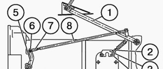
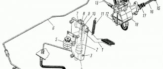
KamAZ clutch drive mechanism diagram
The main components of the drive, which is shown in the photo, are:
- pedal (1);
- hydraulic unit (2) with reservoir (3);
- highway (6);
- executive pneumatic cylinder (16).
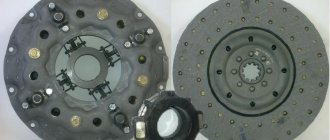
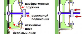
The KamAZ clutch of models 55111, 5320, as well as 43118 and 740 consists of the following structural units:
- clutch housing (A);
- release disc with stamped metal casing (B);
- pressure springs (B) and levers (D);
- one drive disk (E);
- two driven disks (D) with linings (W).
Clutch diagram for KamAZ 740 with diesel engine
The driven discs in the clutch design of a KamAZ truck are made using heat-resistant friction linings, which ensure a long service life of the mechanism. The design of the disks provides a damper for vibrations that occur when the motor shaft rotates. The drive pedal is mounted on special bushings and rarely requires lubrication during operation.
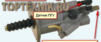
On more modern KamAZ models, single-disc clutches of the so-called Euro type are used. This mechanism is found, for example, on models 6520 or 4308. The supplier of elements for such units is Sachs, and amplifiers made by Wabco are used. There are several clutch models that differ in the amount of transmitted torque. One of the differences between imported amplifiers is the built-in indicator of friction lining wear. Wear is measured by the distance between the amplifier body and the washer on the rod. When the linings are completely worn out, this distance ranges from 23 to 25 mm. In this case, driving a car is still possible, but repair work must be carried out urgently.
Wabco CCGT unit, the wear indicator rod is visible in the upper left part
On some KamAZ models, for example, on 43114, there may be a PGU manufactured by the Volchansky Automotive Unit Plant, in which there is no possibility of adjusting the rod. Typically, such a PGU is either replaced with a customizable one or another rod with adjustability is installed.
Parts and spare parts, maintenance, service and repair
GAZ cars
ZIL cars
KAMAZ vehicles
MAZ cars
KRAZ cars
URAL cars
- URAL-4320, 5557
- Engine YaMZ-236
- __________________
- MAP OF SITE
Adjustments and repairs of clutch KamAZ-5320, 55111
The Kamaz-5320, 55111, 43118 clutch consists of a mechanism and a drive and has the following design features:
– the Kamaz-5320 clutch mechanism has a device for automatically setting the middle drive disk to the middle position when the clutch is disengaged. This device does not require adjustment during operation;
– the shape of the casing ensures fixation of the pressure springs;
– the driven disk has a heat-resistant friction lining with a long service life;
– the clutch pedal is suspended, which does not violate the seal of the cabin, and the metal-plastic bushings in the pedal supports do not require replenishment of lubricant.
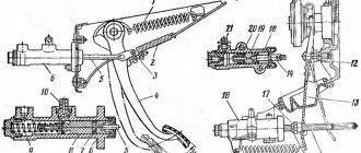
The clutch mechanism Kamaz-55111, 43118, 5320 (Fig. 1) consists of a housing 20, a pressure plate (basket) with a casing 17, pressure springs 16 and pull-out levers 6, two driven disks 1 with friction linings 22 and torsional vibration dampers; middle drive disk 2.
The stamped clutch housing Kamaz-5320 is installed on the flywheel using two mounting sleeves 3 and secured with ten M10 and two M8 bolts.
The driving disks of the Kamaz-55111, 43118, 5320 clutch 4 and middle 2 have four spikes on the outer surface, which fit into special grooves of the flywheel and transmit engine torque to the friction surfaces of the driven disks, the hubs of which are mounted on the splines of the drive shaft of the gearbox or divider
Between the housing 17 of the Kamaz-5320 clutch and the pressure plate 4 there are pressure springs 16, under the action of which the driven and middle drive disks are clamped between the pressure plate and the flywheel.
The middle drive disk of the Kamaz-5320 has a lever mechanism 27. It automatically sets disk 2 to the middle position when the clutch is disengaged.
The Kamaz-5320 clutch release device consists of 4 pull-off levers balanced on a pressure plate with a thrust ring 14, a clutch release clutch 12 with a thrust bearing 10 mounted on the bearing cover of the drive shaft of the gearbox or divider, and a release fork 13 located on the shaft in the crankcase clutch (divider).
The Kamaz-5320 clutch drive (Fig. 2) consists of a clutch pedal 1 with a release spring 11, a master cylinder 2, a compensation tank 5 with working fluid, a pneumohydraulic booster, 18 pipelines and hoses for supplying working fluid from the master cylinder to the clutch booster and air supply from the pneumatic system to the clutch booster.
Fig.1. Clutch KamAZ-43118, 5320, 55111
1 – driven disk; 2 — leading middle disk; 3 — installation sleeve; 4 – pressure disk; 5 — release lever fork; 6 — release lever; 7 – thrust ring spring; 8 — coupling lubrication hose; 9 — spring loop; 10 — release bearing; 11 – release spring; 12 — clutch release; 13 — clutch release fork; 14 - thrust ring; 15 — fork shaft; 16 — external pressure spring; 17 — clutch casing; 18 — heat-insulating washer; 19 — casing mounting bolt; 20 — clutch housing; 21 - flywheel; 22 — friction lining; 23 – internal pressure spring; 24 – input shaft; 25 - torsional vibration damper disk; 26 — internal spring of the torsional vibration damper; 27 — external spring of torsional vibration damper; 8 — driven disk ring; 29 – mechanism for automatically adjusting the position of the middle drive disk
The pneumohydraulic drive booster of the KamAZ-5320 serves to reduce the force on the clutch pedal. It is secured with two bolts to the clutch housing flange (divider) on the right side of the power unit.
Rice. 2. Drive of the clutch mechanism KamAZ-55111, 5320
1 – pedal; 2 – main cylinder; 3.10 – upper and lower stops; 4 – bracket; 5 – compensation tank; 6 – hydraulic pipeline; 7 – lever; 8 – piston pusher; 9 – eccentric pin; 11 – tension spring; 12 – plug; 13 – pipeline; 14 – air release valve; 15 – spherical adjusting nut; 16 – pneumatic piston pusher; 17 – protective cover; 18 – pneumatic hydraulic booster; I – compressed air
When you press the Kamaz-5320 clutch pedal, the fluid pressure from the master cylinder is transmitted through pipelines and hoses to the clutch pneumatic booster to the hydraulic piston and to the piston of the follower device, which automatically changes the air pressure in the power pneumatic cylinder of the booster in proportion to the force on the clutch pedal.
During operation, as the linings of the driven discs wear out, the clutch drive should be adjusted to ensure free movement of the clutch release clutch.
Clutch adjustments KamAZ-43118, 5320, 55111
Clutch adjustments KamAZ-5320, 55111, 43118 during service:
— tighten the bolts securing the pneumatic clutch drive booster:
— check by external inspection the tightness of the clutch drive, if necessary, eliminate the leak and bleed the hydraulic system of the drive;
— check the action of the release springs of the clutch pedal and the clutch release fork shaft lever, and if necessary, correct the faults;
— adjust the clutch drive;
— lubricate the clutch release clutch bearing and the clutch release fork shaft bushing;
— check the fluid level in the clutch compensation tank and top up if necessary;
— drain the condensate from the air-hydraulic booster by unscrewing plug 12 (see Fig. 3).
Adjusting the clutch drive of KamAZ-55111, 43118, 5320 consists of checking and adjusting the free play of the clutch pedal, the free play of the clutch release clutch and the full travel of the pneumatic hydraulic booster pusher.
Checking and adjusting the free play of the Kamaz-5320 clutch release clutch is carried out by manually moving the fork shaft lever from the adjusting spherical nut 15 of the pusher 16 of the pneumatic hydraulic booster of the clutch drive (in this case, it is necessary to disconnect the spring from the lever).
If the free play of the lever, measured at a radius of 90 mm, is less than 3 mm, then adjust it with the spherical nut of the pneumatic hydraulic booster pusher to a value of 3.7. 4.6 mm, which corresponds to a free play of the clutch release of 3.2. 4 mm.
Then check the full stroke of the pusher of the Kamaz-5320 pneumatic hydraulic booster by pressing the clutch pedal all the way, while the full stroke of the pusher must be at least 25 mm; with a smaller stroke, complete disengagement of the clutch is not ensured.
If the pusher stroke of the Kamaz-5320 pneumatic hydraulic booster is insufficient, check the free play of the clutch pedal, the amount of fluid in the master cylinder (Fig. 3) and the clutch reservoir, and if necessary, bleed the clutch hydraulic system.
The free play of the pedal, corresponding to the start of operation of the master cylinder, should be 6.12 mm. It should be measured in the middle part of the clutch pedal area. If the free play is outside the limits specified above, adjust the clearance A between the piston and the master cylinder piston pushrod.
How is the adjustment carried out?
If problems occur with the clutch, you should try to make adjustments. When disc slippage occurs (sluggish acceleration, slight burning smell), it is necessary to set the correct clutch stroke.
If the disks are not fully spaced (difficult switching), you will have to perform more operations:
- Set the pedal stroke.
- Remove air from the drive lines.
- Check the liquid level in the PSU.
When using the Euro unit, only the pedal free play needs to be adjusted. Lubrication and adjustment of other clutch parts during operation of the machine is not provided, except for monitoring the height of the fluid level in the drive reservoir.
By adjusting the clutch on KamAZ 5320 and other models we mean setting the correct gap between the release plate plane and the lever heads, as well as adjusting the free play of the pedal and drive clutch. The permissible free play for the clutch pedal must be in the range from 6 to 12 mm.
The gap is understood as the distance between the points of the central part of the pedal platform when the pedal is released and at the moment the master cylinder begins to turn on. The free play is regulated by rotating the eccentric pin located in the connection of the pedal lever with the upper eye of the amplifier rod. The adjustment is made with the pedal tension spring fully depressed, i.e. the pedal should rest against the upper rubber buffer, which serves as a travel limiter.
For example, on KamAZ 65115 the do-it-yourself adjustment process is as follows:
- Unlock the pin castle nut pin.
- By rotating the finger you need to achieve acceptable free play.
- Tighten the nut and secure it with a cotter pin.
- Check the pedal's full travel. If everything is adjusted correctly, it should be between 185 and 195 mm.
On single-disc MFZ units, the adjustment is similar, but the pedal travel should be from 140 to 150 mm.
Below, the process of adjusting the free wheel is demonstrated using the example of KamAZ 4310, the author of the video is Vladimir Krasikov.
Adjusting the clutch pedal free play
According to the official regulations, the stroke for moving the pedal should be about 6-12 mm, and the measurement itself should be done from the central component of the plate. The pedal must be released until the main cylinder starts working after pressing it. Adjustment is carried out using an eccentric pin; when making adjustments, the pedal must be pressed against the upper stop. The castle nut is tightened as much as possible and the full stroke is replaced, which should be 185-195 mm.
Video about adjusting the clutch pedal
The “EIGHT ATMOSPHERES” channel in its video showed in detail how to increase the clutch pedal pressure on a KamAZ Euro.
Clutch debugging
The next stage of adjustment will be to adjust the free play parameters of the clutch, the value of which should be from 3.2 to 4 mm. The measurement is carried out by rotating the adjusting nut.
The sequence of actions in this case:
- Loosen the fork mounting nut.
- Unscrew the fastening pin, allow it to move freely and remove it.
- Rotate the traction fork until the required clearance is obtained.
- Tighten the nut and install the pin in place.
- Install the locking pin.
- Check the setting. When the pedal is fully depressed, the clutch stroke should be at least 25 mm.
Debugging the full stroke of the amplifier pusher
Before starting to debug the mechanism, it is necessary to find out the stroke length of the pusher. To do this, you need to completely disengage the clutch and measure the stroke. If its value is 25 mm or less, then the clutch will not disengage completely. The driver will notice this problem immediately by the difficulty of shifting gears. To find the cause of the problem, you need to check the level of working fluid in the pusher cylinder. The standard volume is 380 cubic meters. see. If the level of the substance is insufficient, it should be topped up.
Hydraulic system diagram
Using the KamAZ 5511 model as an example, adding fluid is done as follows:
- You need to open the reservoir cap located on the drive housing.
- Add liquid to a level 15-20 mm below the edge of the neck.
The second reason for unsatisfactory operation of the amplifier may be air in the system. In this case, the drive system must be bled. This procedure is somewhat more complicated.
On KamAZ 55102 for this you need:
- Add fluid to normal level.
- Remove the protective cap from the bypass valve (installed on the CCGT housing), put on a rubber hose and lower it into a container with liquid.
- Sharply press the clutch pedal all the way.
- Open the valve one turn and press the pedal until the substance stops bubbling at the outlet of the hose. In this case, it is necessary to constantly add new fluid to the supply tank, not allowing it to fall below the 40 mm mark from the top of the tank.
- Close the valve, remove the hose and replace the cap.
- Add fluid to the operating level.
- To control the quality of work, you must press the pedal all the way - the pusher stroke should not be less than 25 mm.
Diagnostics, adjustment and pumping of KamAZ clutch
KamAZ PGU clutch drive
Adjustment of the KamAZ clutch may be required during the operation of the vehicle, since this unit is subject to serious loads.
If the clutch “leads” or “slips”, if there is extraneous noise and crackling noise when shifting gears, it is necessary to carry out diagnostics and the necessary adjustments.
Diagnostics and adjustment of the KamAZ clutch includes the following actions:
- Visual inspection of the clutch drive.
- Adjusting the free play of the clutch pedal.
- Adjusting the free play of the release bearing clutch.
- Adjusting the full stroke of the clutch pneumatic hydraulic booster pusher.
- Bleeding the clutch hydraulic system.
Inspection and maintenance of the clutch drive
The clutch drive of Kamaz-5320 vehicles includes a clutch pedal with a release spring, a master cylinder, a working cylinder assembled with a pneumatic booster, pipelines and hoses for supplying working fluid from the master cylinder to the pneumatic booster, a compensation tank connected by a hose to the clutch master cylinder. Before any clutch adjustment, the drive should be inspected:
- Check the clutch drive for leaks. To do this, press the clutch pedal two or three times. A strong air leak is detected by ear, and a weak one is detected with a soap solution. Brake fluid leaks are checked visually. If a drive leak is detected, it is eliminated by tightening or replacing leaking elements.
- Check the fluid level in the clutch compensation reservoir. The fluid should be 15...20 mm below the edge of the reservoir neck. If necessary, add liquid to the required level. Mixing liquids of different brands is not allowed.
- Check the action of the release springs of the clutch pedal and the clutch fork shaft lever
- Tighten the bolts securing the pneumatic clutch drive booster. Tightening torque 90… 100 N*m (9…10 kgf*m)
- Drain condensate from the pneumatic hydraulic booster
If the clutch drive is mechanically in good condition, the necessary adjustments are made according to the set values.
Adjusting the clutch pedal free play
The free play of the clutch pedal, corresponding to the start of operation of the master cylinder, should be 6...15 mm. Measure the free play of the pedal with a graduated ruler, which is pressed against the floor of the cabin at the level of the middle of the pedal platform.
If the free play exceeds the specified limits, adjust the clearance between the piston and the master cylinder piston pusher.
To adjust the clutch pedal, set it to its highest position and, having previously uncottered and loosened the castle nut, turn the eccentric pin that connects the upper eye of the pusher to the lever so that the movement of the pedal from the upper stop until the pusher touches the piston is 6...15 mm, after which tighten and cotter the castle nut.
The full travel of the clutch pedal should be 185... 195 mm. It is adjusted by changing the position of the movable stop 4 located in the upper part of the pedal (see Fig. 2.23, i), after which the stop is fixed with a lock nut.
Adjusting the free play of the release bearing clutch
The free play of the clutch release clutch should be 3.2...4.0 mm, which corresponds to the free play of the clutch fork shaft lever of 4...5 mm.
The free play of the clutch release clutch is checked by manually moving the lever with the spring previously disconnected.
Adjust the free play of the fork shaft lever with the spherical nut of the pneumatic booster pusher, and then connect the spring to the lever.
Adjusting the full stroke of the PSU pusher
The full stroke of the pneumatic booster pusher must be at least 25 mm. With a smaller stroke value, complete disengagement of the clutch is not ensured.
The full stroke of the pneumatic booster pusher is checked by pressing the clutch pedal all the way.
If the pusher travel of the pneumatic booster is insufficient, check the free travel of the clutch pedal and the fluid level in the clutch master cylinder reservoir again. If necessary, remove air from the hydraulic system.
Bleeding the clutch hydraulic system
Two people are required to bleed the clutch hydraulic system. Before starting work, clean the rubber protective cap of the bypass valve from dust and dirt, remove it and put a rubber hose on the valve head.
The free end of the hose is lowered into a glass vessel with a capacity of about 0.5 liters, filled to 1/3... 1/4 of the height with working fluid. By sharply pressing the clutch pedal 3...4 times and holding the pedal in the pressed position, unscrew the bypass valve 1/2...1 turn.
The presence of air in the hydraulic system is indicated by the release of air bubbles from the working fluid flowing through the hose into the glass vessel. After the liquid stops coming out when the pedal is pressed, close the bypass valve.
In this case, it is necessary to monitor the level of working fluid in the master cylinder reservoir, which should be no lower than 40 mm from the top edge of the reservoir.
The procedure is repeated until the release of air bubbles from the working fluid flowing through the hose into the glass vessel stops.
Next, having screwed the bypass valve all the way, remove the hose from it, put on the protective cap and add working fluid to the master cylinder reservoir to the normal level.
Drained brake fluid can be reused after it has settled for complete air removal and filtration. The quality of pumping is checked by the full stroke of the PSU pusher.
KamAZ PGU clutch drive
Source: https://remauto.info/regulirovka-sceplenija-kamaz/
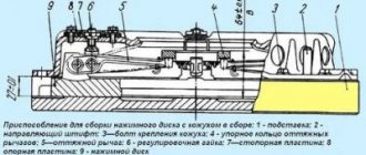
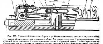
Adjusting the KamAZ clutch basket
By adjusting the clutch basket we mean adjusting the tabs placed on the basket. This debugging can be done with the box removed or adjusted directly on the car.
When performing the task without removing the box, you will need a homemade tool, which is a 3.5 mm thick wire with a 20 mm long end bent at a right angle. Using such an improvised feeler gauge, check the gap between the release bearing and the support ring of the clutch feet. The gap is adjusted using a nut on the PSU rod. You can bring the paws to the ring through the hatch in the upper part of the clutch housing. At the same time, it is important to ensure that the paws fit as uniformly as possible to the surface. But it is more correct and reliable to adjust the clutch removed from the engine.
- Place the assembled pressure plate on the template, which will provide a gap of 29 mm.
- Loosen the mounting bolts.
- Set the position of the stop ring for the feet. All four paws should touch the ring at the same time.
- Check the runout of the working surface of the disk.
- Lubricate the front bearing located in the crankshaft.
- Install the clutch using a mandrel, which will ensure alignment of the mechanism discs and the engine shaft.
This adjustment is carried out only with a double-disc clutch. A unit with one disk does not need such adjustment.
The video from the Auto and Moto channel shows the removal of the clutch and clearly shows the design features, as well as the drive for the operation of the mechanism.
Preparing for adjustment
Before properly adjusting and bleeding the clutch on Kamaz 740, 5511 or other trucks, you must perform the following steps:
- Check the tightness of the drive device. To do this, you need to depress the clutch pedal several times. The presence of a serious air leak can be determined by hearing, and a weaker one can be determined by using a soap solution. If brake fluid is leaving the system, this can be determined visually. If problems are detected in the tightness, the components are tightened or the pipes are replaced.
- Carry out diagnostics of the fluid level in the expansion tank of the drive device. The volume of consumables should be about 15-20 mm below the edge of the tank neck. If required, the fluid level is replenished. It is not recommended to mix supplies from different manufacturers when performing this task.
- Check the operation of the pedal release springs, as well as the system release fork pulley lever.
- Tighten the bolts that secure the pneumatic reinforcement device CC. This procedure is performed using a torque wrench. The tightening torque should be about 90-100 Nm.
- Drain condensate, if any, from the pneumatic hydraulic booster.
Adjusting the clutch operation
To complete the task, you will need a special homemade product in the form of a piece of wire, one side of which should be 2 mm and bent at an angle of 90 degrees. The thickness of the rod is at least 3-4 mm. This size is optimal for controlling the gap between the tab outline and the disc release component. Adjustment is made using the nut of the pneumatic booster device. The legs must be brought to the ring through a hole located in the upper part of the crankcase.
You need to adjust the clutch like this:
- The locking screws are unscrewed with a wrench.
- The stoppers and plates are dismantled.
- Each nut is loosened and released 5 turns; for convenience, it is recommended to use a ratchet. If the penny protrudes beyond the surface of the ring, it must be recessed, checking in advance for the presence of ferodo at the bottom.
- When performing this task, you can also change the spring elements if they are worn out. The paws should be positioned so that they are in equal contact with the ring.
- The disk area runout is checked. If necessary, the bearing device is lubricated. The adjustment gap should be about 29-30 mm.
Maintenance
In addition to settings, the clutch of KamAZ vehicles requires regular maintenance, since this significantly increases the service life and reliability of the mechanism on all KamAZ brands.
Using model 53215 as an example, maintenance consists of the following main points:
- Checking the tightness of the amplifier mounting bolts in the clutch drive circuit.
- Monitoring the tightness of hydraulic lines. There should be no oil stains on them.
- General check of serviceability of pedal assembly parts. All elements must be in good condition and not have large gaps in the connections.
- Checking the presence of lubricant in the clutch bearing and fork connection bushing. To supply oil in the clutch housing there are three points equipped with grease nipples. Oil is injected into them using a syringe.
- Draining condensate from the CCGT housing.
- Checking the fluid level in the amplifier reservoir.
When is clutch replacement required?
If all the work performed does not lead to the restoration of the clutch mechanism, then this becomes one of the signals to replace it.
Other signs of critical wear of structural elements are:
- sudden turning on of the disks, resulting in a hard jerk of the car;
- difficulty engaging all gears, accompanied by a characteristic crash;
- sluggish acceleration of the car, while the engine speed clearly does not correspond to the selected gear and speed;
- smell of burning pads when driving.
If such problems occur, it is necessary to stop moving as soon as possible and repair the mechanism. Continued operation of the vehicle with faulty or burnt-out clutch discs will lead to failure of the gearbox.
Video “Adjusting the clutch on KamAZ”
The video, shot for the Auto and Moto channel, demonstrates the adjustment of the clutch installed on a KamAZ 740 diesel engine.
On cars, depending on the models and trim levels, the following clutch is used:
Pneumohydraulic booster: 1 — lining wear indicator; 2 — washer; 3 - body
— friction, dry, double-disc, with peripheral springs, model 142;
— single-disk, diaphragm, exhaust type models MFZ 350, MFZ 430 f. “SACHS” (Germany) (see Fig. Clutch of models MFZ 350. MFZ 430):
— friction, diaphragm, single-disk, push-type model MF-395 f. "SACHS" (Germany) (see Fig. Clutch model MF-395).
The clutch control drive is hydraulic, equipped with a pneumatic hydraulic booster (PGU), the clutch of models MFZ 430, MFZ 350, MF 395 is PGU (Germany).
Brief technical characteristics of the clutch
Transmitted torque, N.m (kgf.m)
Number of compression springs
Force of springs and diaphragm during clutch, kN (kgf):
At PGU f. “WABCO” has installed lining wear indicator 1 (see Fig. Pneumohydraulic booster). Complete wear of the clutch driven disc linings is indicated by the distance between the plastic housing 3 and washer 2, which, as the linings wear out, becomes equal to 23.25 mm. With new linings, washer 2 should rest against body 3.
Clutch models MFZ430, MFZ350: 1 - gearbox input shaft; 2 — driven disk hub; 3 — driven disk; 4 — pressure disk; 5 - diaphragm; 6 — clutch release clutch.
Clutch model MF-395: 1 — gearbox input shaft; 2 — drive disk hub; 3 — driven disk; 4 — pressure disk; 5 - diaphragm; 6 — clutch; 7 — pneumohydraulic booster
Determine the free play of the clutch release clutch by moving the lever by hand (see Fig. Free play of the clutch release clutch). Disconnect the spring. The normal clutch stroke corresponds to a lever stroke of 45 mm. If the lever stroke is less than 3 mm, then adjust the lever stroke by rotating the spherical nut.
To release the clutch of models MFZ 430, MFZ 350, MF 395, a drive without a gap between the clutch release clutch and the diaphragm is used.
Free play of clutch release
The free play of the clutch pedal (before the master cylinder starts operating) depends on the gap A between the piston and the piston pusher of the master cylinder (see Fig. Adjusting the gap). The normal clearance corresponds to a pedal stroke of 6-12 mm.
Free play of the clutch pedal
Measure the free play of the clutch pedal in the middle part of the clutch pedal area. If the free play of the pedal goes beyond the specified limits, adjust the gap A with the eccentric pin that connects the upper eye of the pusher to the pedal lever (see Fig. Free play of the clutch pedal).
Adjust gap A when the pedal release spring presses the clutch pedal against the upper stop. Rotate the eccentric pin so that the movement of the pedal from the top stop until the pusher touches the piston is 6-12 mm, then tighten and cotter the castle nut.
Removing air from the clutch release hydraulic drive (bleeding) is carried out in the following order:
— remove the plug from the tank and fill the tank with working fluid to a level not lower than 1520 mm from the top cap of the tank filler neck (see Fig. Adjusting the gap):
— remove the cap from the bypass valve, put a hose on the valve head, lower the free end of which into a transparent vessel with working fluid (see Fig. Bleeding the bleed);
- sharply press the clutch pedal until it stops at the pedal travel stop, and then, leaving the clutch pedal pressed, unscrew the bypass valve 0.5-1 turns, and some of the liquid with air bubbles contained in it will come out through the hose. After the liquid stops coming out, close the bypass valve;
TRUCKS GAZ, ZIL, KAMAZ, URAL, MAZ, KRAZ
_________________________________________________________________________________________
Design and parts of the clutch and gearbox KamAZ-65115
Technical characteristics of the clutch of the Kamaz-65115 car
Rice. 1. Free play of the clutch release clutch of Kamaz-65115 vehicles The Kamaz-65115 clutch is a friction, dry, double-disc, with a peripheral arrangement of springs model 142 or a diaphragm double-disc model 17, or a single-disc, diaphragm, pull-type model MFZ 430 from F&S (Germany). The clutch control drive is hydraulic, equipped with a pneumatic booster. In the clutch control drive of model 17, to reduce the force on the pedal, an additional servo spring is introduced, attached at one end to the top of the pedal, and at the other to the bracket. Brief technical characteristics of the Kamaz-65115 clutch Clutch model - 142 / 17 Transmitted torque, N/m (kg/cm) - 833 (85) / 1350 (135) Number of pressure springs - 24 / - Diaphragm - - / 1 Spring force and diaphragm with clutch, kN (kgf): - on - 13.15-15.3 (1315-1530) / 18.5 (1850) - off - 14.05-16.2 (1405-1620) / 17.5 (1750) Determine the free play of the clutch release clutch by moving the lever by hand. Disconnect the spring. The normal stroke of the clutch corresponds to a lever stroke of 4-5 mm. If the lever stroke is less than 3 mm, then adjust the lever stroke by rotating the spherical nut. The free play of the clutch pedal (before the master cylinder starts operating) depends on the gap A between the piston and the master cylinder piston pusher. The normal clearance corresponds to a pedal stroke of 6-12 mm.
Rice. 2. Free play of the clutch pedal KamAZ-65115
Rice. 3. Adjusting the gap between the piston and the piston pusher of the Kamaz-65115 clutch master cylinder To adjust the gap, unscrew and loosen the castle nut of the eccentric pin and, by rotating the eccentric pin, set the required free play of the clutch pedal. Removing air from the hydraulic clutch release drive of KamAZ-65115 (bleeding) is carried out in this order: - remove plug 5 from the tank and fill the tank with working fluid to a level not lower than 15-20 mm from the top cap of the tank filler neck; — remove the cap from the bypass valve, place a hose on the valve head, the free end of which is lowered into a transparent vessel with working fluid; - unscrew the bypass valve 0.5-1 turn and sharply press the clutch pedal all the way to the pedal stop until air bubbles stop emitting from the working fluid; — during pumping, add working fluid to the system, not allowing its level in the tank to drop below 40 mm from the upper edge of the filler neck; — after pumping is completed, with the pedal pressed all the way, screw the bypass valve all the way, remove the hose from the valve head, and put on the cap; — after bleeding the system, add fresh working fluid to the tank to the normal level. The quality of pumping can be determined by the full stroke of the pusher) of the pneumatic booster of the PGU clutch KamAZ-65115.
If the fluid level in the master cylinder is normal and there is no air in the fluid, then the full stroke of the pusher should be at least 25 mm. To measure the full stroke of the pusher, press the clutch pedal all the way. On cars, depending on models and trim levels, gearboxes of models 142, 152, 161 or ZF-9S109 (Germany) are used. The Kamaz-65115 gearbox KPP 142 is mechanical, five-speed, consists of a main gearbox; Model 152 is ten-speed, differing from model 142 by the presence of a two-stage divider located in front of the main box. The control of Kamaz-65115 gearboxes, gearboxes 142 and 152, is mechanical, remote, with a rocker lever mounted on the engine; the divider control is selector, pneumomechanical using a switch on the gear lever. The gearbox of the 161 gearbox is mechanical, eight-speed, includes a main four-speed gearbox and a planetary range located behind the main gearbox. The gear shift lever support of the original design is installed on the box cover. It contains the rod and lever for controlling the gearbox, a mechanism for protecting against accidental engagement of reverse gear and pneumatic valves for switching the range multiplier. The ZF-9S109 gearbox is a mechanical, nine-speed, which has an additional low gear compared to the 161 model. Adjust the remote drive for controlling the gear shift mechanism in Kamaz-65115 gearboxes of models 142, 152, with the gear shift lever in the neutral position in the following order: - loosen the tightening bolts 5 (see Fig. 4) and, by unscrewing the bolts 3, ensure a gap of connection by screwing the adjusting flange 4 onto the rod 6 one or two turns; — having loosened the lock nut 1, screw in the set screw 2, thereby stopping the movement of the rod 7; — having loosened the lock nut 1, screw in the set screw 2, thereby stopping the movement of the gear shift lever; — by rotating, move the adjusting flange 4 along the thread until it makes contact over the entire surface with the flange of the rod 7. Install bolts 3 and tighten the tightening bolts 5; — unscrew the set screw 2 by 21 mm and lock it with a lock nut; — unscrew the 2 by 31 mm set screw and lock it with a lock nut.
Fig.4. Adjusting the Kamaz-65115 clutch drive Check the gap in the Kamaz-65115 gearbox divider activation valve with the clutch release drive adjusted and the nominal compressed air pressure in the brake pneumatic drive in the following order: - remove the rubber dust fuse 1; — smoothly press the clutch pedal all the way; — use a feeler gauge to check the gap between cover 2 and rod stop 3.
Fig.5. Clutch drive KamAZ-65115 / Fig.6. Kamaz-65115 gearbox divider mechanism / Fig.7. Set screw and lock nut At the rated compressed air pressure in the brake pneumatic drive, the gap should be 0.2...0.3 mm. Check the gap no later than 30 seconds after disengaging the clutch. If necessary, adjust the gap by moving the stop (flag) 4 of the valve stem. After setting the required value, secure the stop with nuts, lock the nuts with bend washers. Check the travel of the gear divider lever at the Kamaz-65115 gearbox if there is compressed air in the brake pneumatic drive. To measure: — remove the cover of the inspection hatch of the gear divider switching mechanism; — press the clutch pedal all the way; — moving the gear divider control switch from the upper position to the lower position or vice versa, measure the stroke of the lever in the center of the hole. The normal stroke is 16.5…19.0 mm.
Fig.8. Drive for controlling the gear shift mechanism of the Kamaz-65115 gearbox 1 - gear shift lever; 2 — gear shift lever support; 3 - traction; 4 - rod; 5 — lever; 6 — rocket rod bracket; 7 — jet thrust; 8 — protective casing; 9 — shank; 10 - nut. Adjusting the travel of the Kamaz-65115 gearshift lever in the following order: - loosen the locknuts and unscrew the set screws; — set the switch on the gear shift handle to the lower position; — press the clutch pedal all the way; — screw in the rear set screw until it makes contact with the lever, then tighten it another 1/4 turn and lock it with a lock nut; — set the switch to the upper position and press the clutch pedal all the way. Install the front set screw in the same manner as you installed the rear set screw. Adjust the remote drive for controlling the gear shift mechanism of the Kamaz-65115 model 161 and ZF-9S109 gearboxes with the gear shift lever in the neutral position in the following order: - fix the rod 3 with the technological rod 4 (d=4mm, l=100mm) in support 2; — install the shank 9 into the conical hole of the lever 5, tighten the nut 10 to a torque of 40...50 Nm, for model 161, use a cotter pin; — remove the technological rod; — deviation of the general plane of symmetry of lever 1 and rod 3 from the vertical plane of no more than 2 mm is ensured by changing the length of rod 7. Oil drain plugs in the Kamaz-65115 gearbox housings, gearboxes 142, 144, 152, 154 Check the oil level in the gearbox housing with a pointer, mounted in plug 2 (see Fig. 9/11) of the oil filler neck.
The normal level should reach the top mark on the indicator. When checking the level, do not screw in the plug, but only insert it into the hole until it touches the thread. For ZF-9S109 model gearboxes, the oil level must reach the lower edge of the filler (control) holes 3, located symmetrically on both sides of the box (see Fig. 10).
Fig.9. Oil drain plugs in the gearbox housing 161 / Fig. 10. Oil drain plugs in the Kamaz-65115 ZF-9S109 gearbox housing (bottom view) / Fig. 11. Oil drain plugs in the crankcase of the Kamaz gearbox model KPP142/152 Drain the oil from the crankcase when it is still warm from heating during operation: for gearboxes of models 152 and 142 - by unscrewing plugs 1, 3, 4 on a Kamaz-65115 vehicle with a divider (1 and 4 - without divisor); for the model 161 box - by unscrewing the oil filter 1, installed at the rear end of the range housing, and plugs 2 and 3 of the crankcase; for model ZF-9S109 - by unscrewing the plugs of one of the filler holes 3 and the plugs of 1 and 2 drain holes. Clean the magnetic plugs from dirt and, after draining the used oil, install them in place.
_________________________________________________________________________________________
- GAZ-3307 clutch maintenance
- Steering system GAZ-3307
- Gearbox parts for GAZ-3307
- Maintenance of the rear axle GAZ-3307
- Maintenance of the fuel system of the D-245 diesel engine
- Clutch GAZ-3309 with a diesel engine
- Operations for disassembling the GAZ-3309 gearbox
- GAZ-3309 front axle service
- Repair of cardan shafts of GAZ-3309 cars
_________________________________________________________________________________________
_________________________________________________________________________________________
- Operations for assembling basic components of the ZIL-130 engine
- Service and repair operations for the ZIL-130 gearbox
- Maintenance and repair of ZIL-130 clutch
- Repair and adjustment of the rear axle ZIL-130
_________________________________________________________________________________________
- KAMAZ-4310, 43118, 43114
- KAMAZ-5320, 55111, 53212, 5511, 55102
- KAMAZ-65115, 6520, 65117
- KAMAZ-4308
- Engine KAMAZ-740
_________________________________________________________________________________________
- Parts of the cylinder block and head of the YaMZ-236 engine
- Service maintenance of the YaMZ-236 piston group and crankshaft
- Diagnostics and technical adjustments of the YaMZ-236 engine
- Design and adjustment of fuel injection pump and injectors of the YaMZ-236 engine
- Cylinder block and piston YaMZ-238
- Components of the YaMZ-238 diesel fuel supply system
- Design and adjustment of the fuel injection pump of the YaMZ-238 diesel engine
- Technical design of the YaMZ-239 gearbox
_________________________________________________________________________________________
- Components of the front axle and steering rods of the Maz-5516, 5440
- Steering system of Maz-5516, 5440 cars
- Clutch and gearbox parts Maz-5516, 5440
- Maintenance of drive axles of MAZ-5516, 5440 vehicles
- Power steering for Maz-5551, 5335 cars
- Maintenance of cardan transmission of Maz-5551, 5335 cars
- Maintenance and adjustment of clutch MAZ-5551, 5335
- Repair and service of the rear axle of MAZ-5551, 5335 cars
_________________________________________________________________________________________
- Gearbox Ural-4320
- Construction and adjustment of Ural-4320 bridges
- Maintenance of transfer case Ural-4320
- Steering components Ural-4320
_________________________________________________________________________________________
- Servicing the KRAZ-255, 260 gearbox
- Steering mechanism and power steering Kraz-255, 260
- Adjustments and repairs of the power steering cylinder and steering rods of the Kraz car
- Drive axle components and drive shafts Kraz-255, 260
Design and principle of operation
The operation of the mechanism is based on the principle of sliding friction force.
The KamAZ clutch device is used for:
- transfer of rotation from the crankshaft;
- gradual transfer of gears;
- reducing rotational vibrations;
- disconnecting the transmission device from the engine for a short moment.
In a car, gear shift occurs when the clutch pedal is depressed, there is no connection between the engine and the gearbox, and rotation is not transmitted.
The KamAZ leaf clutch consists of the following parts:
- a flywheel that receives rotation from the engine and transfers it to the gearbox through the basket;
- pressure plate complete with springs;
- drive disk assembly with linings and vibration damper;
- plug assembly that breaks the connection;
- an axial shaft to which rotation is applied;
- release bearing;
- spring that reduces vibrations;
- hood;
- structural linings located on the drive disk to reduce friction.
How to adjust the KamAZ clutch
Maintenance is carried out regularly. Increasing the pedal stroke leads to incomplete disconnection of the flywheel and gearbox. This device causes the gears to come into contact, and the load on the teeth of the gears increases. If the accelerator stroke is insufficient, the drive disk does not engage, rotation is not fully transferred, and the machine stops.
Adjusting the clutch on a KamAZ allows you to eliminate faults that are diagnosed based on the following symptoms:
- at the beginning of departure - jerks;
- the friction pedal sticks;
- the accelerator is slow;
- if you check the drive fluid level, a leak is detected;
- extraneous sounds are heard.
The need to adjust the clutch on a KamAZ is checked by measuring the distance from the bottom of the pedal to the floor surface of the driver's seat - the indicator should be 16 cm.
Without removing the box
Adjustment of the clutch operation is carried out by removing the gearbox. But if adjustment is required under road conditions, then the work is performed without removing the structure.
You will need a homemade device in the form of a piece of wire, one side of which is 2 cm long and bent at an angle of 90˚. The thickness of the rod is at least 3-4 mm; this size is convenient for controlling the clearance between the disc release element and the contour of the legs.
The adjustment is made using the pneumatic booster nut. The legs are connected to the ring through a hole at the top of the crankcase. Elements are placed as equally as possible to the area.
The procedure is as follows:
- Unscrew the locking bolts.
- Remove stoppers and plates.
- The nuts are all loosened equally by 5 turns; ratchets are used for convenience.
- If a nickel protrudes beyond the surface of the ring, then it is recessed, first checking for the presence of ferodo underneath.
- The springs can be replaced at the same time.
- The paws are placed so that they touch the ring equally. Then the runout of the disc area is analyzed.
- The front bearing is lubricated. Select an adjustment gap of 29-30 mm.
Setting up the mechanism without removing the gearbox is done in the case of a double-disc clutch; single-disc clutches are not adjusted this way.
How to adjust pedal free play
Check the movement of the coupling by moving the axial shaft lever away from the pusher nut. If the free distance measured at 90˚ is less than 3 mm, then to adjust it, rotate the pusher screw so that the distance of free movement of the coupling is 3.1-4 mm.
The stroke of the amplifier pusher is checked when the accelerator is pressed - the indicator should be more than 2.5 cm. A smaller value does not ensure effective activation. If the pusher stroke of the pneumatic hydraulic booster is less than recommended, then:
- adjust the free play of the clutch pedal;
- control the amount of liquid in the main cylinder container;
- remove the atmosphere from the hydraulic device.
The pedal movement should correspond to the size of 6-15 mm, it is measured in the middle of the pedal. If it is exceeded, the clearance of the piston and pusher is set using an eccentric element connecting the hole at the top of the pusher and the accelerator.
How to adjust the cart
The basket's feet are adjusted on the removed disk or through a gap in the flywheel directly on the machine.
- When the machine is in the pit, remove the box using a winch.
- Inspect the release bearing, springs and collets.
- Unscrew the fastening of the disk to the engine flywheel.
- Remove the pressure mechanism while holding the drive disk.
- Inspect the surface and make adjustments to the paws relative to the area of the disk.
- Check the change in the position of the paws using a plate, taking into account that their round surfaces should touch the template located on the hub.
- After adjusting the clutch basket, the hardware is tightened until it stops. Clutch assembly is done in reverse order.
Adjusting the KAMAZ clutch: instructions
Reliability, excellent performance, efficiency - all this can be said about KAMAZ trucks. The machines are in demand for household, commercial and military purposes. The key to long-term and trouble-free operation is constant checking of the technical condition. Adjusting the KAMAZ clutch is always relevant. This brand is usually equipped with a dry double-disc or single-disc clutch (friction type). During its entire service life, the unit experiences enormous loads. Competent selection of spare parts and timely maintenance will guarantee long-term operation. Adjusting the KAMAZ clutch basket requires experience and certain knowledge.
Setting is necessary when:
- A crackling sound occurs when changing gears.
- Slipping at high speeds.
- Changing the free play of the clutch pedal (it has certain digital values).
If you ignore these signs, expect a serious accident!
KAMAZ clutch adjustment technology
Removing and adjusting the KAMAZ clutch is carried out in several steps.
Adjusting the free travel of the KAMAZ clutch pedal
The pedal must have a play of 6 to 12 mm. Measurements are taken from the central part of the plate. The pedal must be lowered until the main cylinder starts working. If there is a deviation from the norm, adjust the distance between the PSU pusher and the stop at the top.
To do this, you will need an eccentric pin connecting the pedal to the top eye of the pushrod. The pedal for traction must press the clutch pedal against the stop from above. The finger is turned so that the gap between the piston and the PSU pusher is in the range from 6 to 12 millimeters. When finished, tighten the castle nut securely. The full pedal travel should be approximately 19 centimeters.
Adjusting the KAMAZ clutch
The manufacturer recommends maintaining a free play value in the range from 3.2 to 4 millimeters. To measure, you will need to move the fork shaft lever by hand. It must move in the direction from the spherical nut of the pusher. It is located on the pneumatic or hydraulic clutch drive amplifier. Adjusting the KAMAZ clutch clearance will require removing the spring: the lever should move no more than five millimeters. If the free play is less than three millimeters, then it is adjusted using a spherical nut. The idle speed of the clutch must be from 3.2 to 4 millimeters.
Adjusting the KAMAZ clutch drive
To measure the function indicator, it is worth pressing the pedal all the way. If the value is less than 24 mm, then complete shutdown will not occur. It is necessary to measure the free play of the pedal and the volume of fluid in the master cylinder. 380 cubic centimeters is the total volume in the hydraulic drive. If the data does not satisfy the requests, it is important to get rid of air in the system. This will return all indicators to normal.
Adjusting the KAMAZ clutch pressure plate
During this operation, you must strictly follow the sequence:
- Initially, the gearbox is dismantled. You can't do it without helpers.
- Remove the clutch basket.
- The clutch discs are dismantled: first the driven one, then the middle one, and finally the driving one.
- New parts are being installed. The order is already reversed.
- It is important to adjust the nickel of the KAMAZ clutch basket.
- The correct installation of all mechanisms is checked in detail.
- The gearbox returns to its place.
If there is only one disc in the clutch design, the job is much easier!
But even a KAMAZ single-plate clutch, adjusting its parts will require serious skills, strength and knowledge. Don't take risks - entrust the matter to professionals. Or do a one-time replacement with a real mechanic. For some mechanics, adjusting the KAMAZ double-disc clutch without removing the gearbox is a reality.
Adjusting the legs of the KAMAZ clutch basket
The case is carried out in several steps:
- The checkpoint is dismantled. Use wrenches to unscrew the fastening bolts.
- Raise the box: it is better to do this with a cargo winch.
- Check the condition of the coupling, tension spring element, and release bearing.
- Unscrew the screws connecting the pressure plate and flywheel. To dismantle the pressure element, the driven disk must be supported.
- Carry out troubleshooting of all parts of the system (preferably).
- Check the condition of the release bearing. A working mechanism rotates easily, without unnecessary sounds.
- Conduct a visual inspection of the working surface of the pressure plate feet. After installing the new parts, the KS feet are adjusted. In this case, you will need a flat slab.
The location of the paws is oriented towards the working position of the pressure plate surface. Important : the operation does not require removing the joint from the additional flywheel. In this work you will need wrenches for the adjusting screws. The KS feet must be positioned so that the distance from the working plane of the pressure plate to the upper edges of the spherical protrusions on the inner surface of the feet is no more than 41 millimeters. But 40 mm is better.
To check the installation of the paws, you will need a special plate. The spherical protrusions must touch the control plate (it is installed on the hub). After completing the adjustment, all screws securing the support plates are tightened until they stop. Assembly proceeds in reverse order.
Source: https://gruzovik.biz/articles/regulirovka-scepleniya-kamaz-instrukciya
Malfunctions and what to do
Repair of the KamAZ clutch can be delayed if the machine is regularly maintained.
Load, road surface, driving skills affect the intensity of destructive processes:
- wear of the control drive;
- erasing contacting areas;
- change in the tightness of devices.
To identify malfunctions, before adjusting the clutch drive, the automobile clutch is diagnosed:
- Inspect the drive for leaks, determine the degree of destruction of the pedal springs and fork lever.
- Bring the distance of free movement of the cylinder pusher and the fork axle lever to the recommended parameters.
- Lubricate the balls of the release collet and the clutch fork shaft.
- Determine the liquid level in the main cylinder tank and adjust the amount to normal.
- Tighten the bolts of the pneumatic booster device.
- Change the fluid in the hydraulic drive circuit once a year.
Clutch malfunctions are eliminated as the linings of the drive discs wear out.
If it slips
If the mechanism does not turn on completely, the car accelerates slowly or loses power when climbing the highway, or a burnt rubber smell is heard, then there is an explanation for the problems:
- there is no clearance between the bearing pressing on the basket petals and the stop ring;
- oil has leaked between interacting surfaces;
- friction gaskets have become unusable;
- the clamping springs have lost their shock-absorbing qualities or are broken.