Category: KAMAZ
- When to adjust wheel toe
- Parameters affecting driving
- Checking wheel settings
When it comes to driving safety, some drivers neglect to properly configure the car's wheels. Meanwhile, the unit affects the service life of the vehicle, and the KamAZ wheel alignment plays a major role here.
The setting of the parameter is influenced by many indicators, such as the vehicle load, the level of air pressure in the tires, etc. That is why, in order to correctly adjust the toe-in on a KamAZ, as many of them as possible are taken into account. There is no exact period; this factor is based on the driver’s experience, knowledge of the structure and behavior of the car. Based on a number of indicators and signs, you can clearly orient yourself about the coming moment. Let's look at this issue in detail.
KamAZ 43118:
Wheel toe adjustment KAMAZ 55111
Question No. 13. Adjusting the toe-in of the front wheels of ZIL
how to adjust KAMAZ wheel bearings part 2
Do-it-yourself wheel alignment
Truck wheel alignment stand Techno Vector 7 Truck | Wheel alignment for trucks
Question No. 13.1 Adjusting the toe-in of the front wheels of ZIL
TruckCam. Toe adjustment
Adjusting the brake mechanism on a KamAZ vehicle
Homemade do-it-yourself ruler for adjusting wheel toe from a caliper
Maintenance
During daily maintenance, visually check Install the missing caps on the chamber valves.
At TO-1 , tighten the wheel nuts, bring the tire pressure to normal, and lubricate the steering knuckle pins.
the wheel nuts with a torque of 25-30 kgf m evenly, through one nut in two or three steps, starting from the top and checking the lateral runout of the tire along the middle part of the tire sidewall. To do this, place a square or plumb line on the side of the tire and, by rotating the wheel, determine the maximum lateral runout of the tire, which should not be more than 5 mm. If the deviation is greater, loosen the wheel nuts and retighten them in the order described above, thereby reducing the lateral runout of the tire.
To inflate tires, unscrew cap 15 of the pressure regulator (see Fig. 209) and screw on the hose fitting. Before inflating tires, it is necessary to reduce the pressure in the air cylinders to 6.2-6.5 kgf/cm2. In this case, the regulator turns on and the compressor begins to pump compressed air.
When inflating tires, in order to avoid injury if the locking ring accidentally jumps out of the rim groove, you must not be in the area of the wheel being inflated.
It is allowed to inflate the tire without removing the wheel from the hub when the air pressure decreases by no more than 40% compared to the nominal and you are confident that the decrease in pressure does not interfere with the correct installation of the lock and bead rings.
At TO-2:
— check the cotter pins of the ball pin nuts and steering knuckle arms;
— adjust the amount of toe-in of the front wheels;
— with the wheels hanging, check the condition of the pivot joints, adjust the front wheel hub bearings;
- Rearrange the wheels if there is increased or uneven tire tread wear.
the front wheel alignment in the following order:
— Check the pressure in the tires of the front wheels. If necessary, press it to normal;
— set the front wheels to a position corresponding to the vehicle moving in a straight line;
— use a ruler, model 2182, to measure the distance between the brake drum flanges at the rear at the height of the wheel centers;
- roll the car forward half a revolution of the front wheels:
— measure the distance in front at the same points as before, at the height of the wheel centers. The difference in the measurement results before and after rolling the car will determine the amount of wheel toe. If the toe-in does not meet the standard, adjust it by loosening the bolts of the terminal connection of both tips and screwing the rod into the tips when the toe-in is large and out when it is small. After this, tighten the nuts of the bolts securing the tips, ensuring a tightening torque of 5.0-6.2 kgf m.
the front wheel hub bearings (with the wheels hanging) by rocking the wheels hung on a lift in a direction perpendicular to the plane of rotation of the wheel, as well as by rotating them by hand. When the bearings are properly tightened, the wheel rotates freely, without jamming and has no axial movement or swing. If the wheel turns hard and is not due to friction between the brake pads and the drum, or if play is felt when the wheel is rocked, adjust the torque of the wheel bearings.
At the service station, check the condition of the hub bearings (with the wheel hubs of the middle and rear axles and the front axle removed), change the lubricant in the hub bearings of the rear and front wheels; secure the spare wheel holder.
To check the wheel hub bearings and replace the grease in them, remove the rear and front wheel hubs. Take care not to damage the seals. Replace damaged seals.
To remove the front wheel hubs, perform the following operations:
— remove the hub cover 9 (see Fig. 166);
— unscrew the lock nut 10 securing the bearings and remove washers 7 and 8;
— unscrew nut 6 securing the bearings;
— remove the hub using a puller I-801.38.000 (Fig. 171), to do this, secure washer 4 with bolts 8 to the hub. Resting tip 2 against the steering knuckle axle, place the grips 1 by the washer clamps 4 and secure them with screws 7. Using handle 5, screw screw 3 into the yoke 6 and remove the hub from the axle.
Rice. 171. Removing the front wheel hub using a puller I801.38.000
When removing the rear wheel hubs, first remove the axle shafts, to do this:
— unscrew nuts 26 (see Fig. 141) securing the axle shaft to the hub;
— remove spring washers 27; remove expansion bushings 28;
— screw two M12X1.25 bolts into the holes of the axle shaft flange until it moves;
- Remove the axle shaft and axle flange gaskets. Next, remove the hubs using a puller I-801.38.000 (Fig. 172) in the same way as removing the front wheel hubs, securing the washer to the hub studs with nuts 1.
Rice. 172. Removing the rear wheel hub using a puller I-801.38.000
Check the condition of the bearings. The working surfaces of the outer wheels and rollers should not have visible marks, burrs, cracks, or tarnish. The rollers must rotate freely in the separator.
Before lubricating the bearings, remove the old grease, and then carefully fill the space between the rollers and the cage with the required amount of grease (see Appendix 3) evenly around the entire circumference.
Adjust the front wheel hub bearings in the following order:
— remove the hub cover and loosen the bearing nut, then, turning the hub (wheel), check for ease of rotation. If there is stiff rotation that is not due to friction between the brake pads and the drum, remove the hub and determine if it is caused by damage to the bearings or seal;
— turning the hub (wheel) in both directions to correctly install the rollers between the bearing rings, tighten the bearing nut, tighten the bearing nut until the hub (wheel) rotates tightly;
— unscrew the nut approximately 1/6 of a turn until the nut pin aligns with the nearest hole in the lock washer, check the hub (wheel) for ease of rotation without noticeable play;
— tighten the locknut securing the bearings with a torque of 14-16 kgf m and bend the lock washer of the locknut onto one of its faces to lock the locknut;
— check the rotation of the hub (wheel) by turning it in two directions. Rotation should be free and even.
When checking the rotation of the wheel hub, axial play is not allowed.
Check the quality of bearing adjustment during a test run of up to 10 km. If strong heating is observed, the adjustment must be repeated.
Adjust the wheel hub bearings of the middle and rear axles in the same way as described above. Tighten nut 26 (see Fig. 141) of the axle shaft studs, ensuring a tightening torque of 12-14 kgf m.
Do-it-yourself wheel alignment on KAMAZ video
Question No. 13. Adjusting the toe-in of the front wheels of ZIL
Toe Adjustment Ruler
Do-it-yourself wheel alignment, old-fashioned method.
Homemade do-it-yourself ruler for adjusting wheel toe from a caliper
Do-it-yourself wheel alignment
Truck convergence Zil bull
Light ruler for do-it-yourself wheel toe adjustment on any car)
Question No. 13.1 Adjusting the toe-in of the front wheels of ZIL
how to remove jet rods on a Ural Kamaz without a sledgehammer and pit 2
Wheel toe adjustment KAMAZ 55111
Question No. 13. Adjusting the toe-in of the front wheels of ZIL
how to adjust KAMAZ wheel bearings part 2
Do-it-yourself wheel alignment
Truck wheel alignment stand Techno Vector 7 Truck | Wheel alignment for trucks
Question No. 13.1 Adjusting the toe-in of the front wheels of ZIL
TruckCam. Toe adjustment
Adjusting the brake mechanism on a KamAZ vehicle
Homemade do-it-yourself ruler for adjusting wheel toe from a caliper
FRONT AXLE. WHEELS. TIRES
Technical characteristics of the front axle assembly
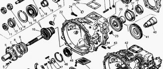
The front axle (Fig. 165) is continuous, with fork-type rotary cams and cylindrical king pins. 5 pin bushings are pressed into the holes of fists 6 and 21 under the kingpin 10, acting as plain bearings. From axial movement, the kingpin 10 is secured by a wedge 31 and a nut 29 with a washer 30. The kingpin is installed upside down with a slot. After installing the kingpin, the holes in the knuckles are closed with covers 3 and 12 with gaskets 4 to protect the bearings from dirt and dust. The upper cover, unlike the lower one, has a safety valve 11 for the release of lubricant. Between the lower ends of the beam eyelet 24 and the knuckles, support bearings are installed, consisting of a support ring 18 and a washer 20. The washer is secured against rotation by pins 19 in the bores on the steering knuckles. Between the upper ends of the beam eyes and the knuckles, washers 15 and 16 with a thickness of 1.5 and 0.25 mm are installed, with the help of which the axial clearance in the pivot joint is adjusted. Sliding bearings and support bearings are lubricated through oil nipples 9.
The upper 25 and lower 23 and 28 levers are secured in the knuckles with nuts 7 with cotter pins 8. The turning levers in the knuckles are secured with segment keys 22. The angles of rotation of the knuckles are limited by stops 26, screwed into the flanges of the steering knuckles and fixed with nuts 27. The stops rest against maximum rotation of the wheels into the bosses on the axle beam. The 13 wheel hubs are secured to the knuckle axles (Fig. 166) with nut 6, lock nut 10 and lock washers 7 and 8. The ends of the hub spokes end in tapered supports to fit the tapered surface of the rim. The cone angle of 28° provides, when tightening nuts 3 (tightening torque 25-30 kgf·cm), the friction force necessary to keep the rim from turning during braking. In the body of the hub between the spokes there are five holes for bolts 15 securing the brake drum with self-locking nuts 16. The hub assembly with the brake drum is balanced. It rotates on two tapered roller bearings 11 and 14. There are markings on the inner and outer races of the bearings, which must match exactly for both races.
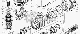
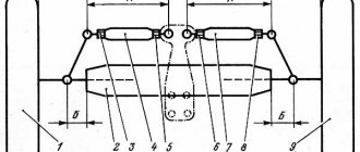
Rice. 165. Front axle and steering knuckles: 1—bolt; 2, 30—spring washers; 3—lower knuckle cover; 4—cover gasket; 5—pin bushing; 6—fist of the rotary front axle, left; 7, 27, 29—nuts; 8—adjustable cotter pin; 9—oiler; 10—king pin; 11—safety valve; 12—upper steering knuckle cover; 13—o-ring; 14—oil seal cage; 15—fist washer; 16—adjusting washer; 17—semi-ring of the oil seal; 18—support bearing ring; 19—pin; 20—support bearing washer; 21—right rotary fist; 22-segment key; 23—steering knuckle lever to steering linkage rod, right; 24—front axle beam; 25—steering knuckle lever to the bipod rod of the steering mechanism; 26—steering knuckle stop; 28—steering knuckle lever to steering linkage rod; 31—pin wedge
Rice. 166. Front axle assembly with hubs, wheels, brake mechanism and steering linkage rod: 1—wheel and tire assembly; 2—wheel clamp; 3. 16—nuts; 4 hairpins; 5—bolt with washer assembly; 6—bearing nut; 7—lock washer of the nut; 8—lock washer of the lock nut; 9—hub cover; 10—lock nut; 11, 14—bearings; 12—gaskets; 13—hub: 15—bolt; 17—brake
The bearing unit is protected from dust and dirt from the outside by a cover with gasket 12, and on the reverse side by a cuff 22 installed in the hub bore. The working edges of the cuff rest on ring 19.
How to do wheel alignment on KAMAZ
Question No. 13. Adjusting the toe-in of the front wheels of ZIL
Toe Adjustment Ruler
KamAZ and metal, how to do it is not necessary. / truck and iron
how to adjust KAMAZ wheel bearings part 2
Do-it-yourself wheel alignment
Do-it-yourself wheel alignment, old-fashioned method.
Light ruler for do-it-yourself wheel toe adjustment on any car)
How to make KAMAZ economical
How to do your own wheel alignment in a car
Checking wheel settings
To make wheel alignment yourself on a KamAZ, follow these steps:
- Place the car on a horizontal surface, in a straight position, inflate the tires to the required level;
- Measure the gap distance on the wheel axles of the rim of the first and 2nd wheels; for this purpose, a sliding ruler is used, installed in front of the driven pair of car wheels in a horizontal plane;
- Drive the car, leaving the meter in place, and take a measurement. The difference between the measurements corresponds to the norm for the KamAZ modification;
- Before adjusting the toe-in of the wheels on a KamAZ, remove the fixing bolts of the tips from the rod located transversely. Afterwards, the thrust is reduced (larger value) or the toe-in is lengthened (smaller value);
Adjusting the toe-in of KamAZ steering wheels:
- Having completed the adjustment, the tips are fixed, the force is 50-60 Nm.;
- The rotation angles are adjusted using clamps screwed into the cams of the front axle (the normal value is 45°);
- The clamps are screwed in all the way, the wheels are turned to the right, connecting the rod and rod to the lever;
- If you change the length of the rod, remove the protection casing, unscrew the lock, and turn the tip. Then unscrew the adjustment bolt and secure it with a control nut;
- Turn the wheels to the left and secure the lock.
- The rotation angle is 26°; the parameter is measured using a special device.
The camber and angles of the hinge rods on KamAZ are not adjustable; they are set when replacing old parts.
How to make a wheel alignment on a Kamaz
When it comes to driving safety, some drivers neglect to properly configure the car's wheels. Meanwhile, the unit affects the service life of the vehicle, and the KamAZ wheel alignment plays a major role here.
The setting of the parameter is influenced by many indicators, such as the vehicle load, the level of air pressure in the tires, etc. That is why, in order to correctly adjust the toe-in on a KamAZ, as many of them as possible are taken into account. There is no exact period; this factor is based on the driver’s experience, knowledge of the structure and behavior of the car. Based on a number of indicators and signs, you can clearly orient yourself about the coming moment. Let's look at this issue in detail.
Tire air control system
The vehicle may be driven on paved roads and compacted dirt roads only with a rated tire pressure corresponding to the maximum load on the tire. On difficult sections of the route (wetlands, virgin snow, loose sand), a short-term decrease in the internal air pressure in the tires is allowed, while the maximum speed and mileage must correspond to the standards indicated in the table.
196 (2.0; 1.96) to nominal
The system is controlled from the driver's cabin. The tire pressure regulation system includes: air lock valves, pneumatic lines, air supply seal units, heads with air supply cuffs and controls for the tire pressure regulation system.
When to adjust wheel toe
Before adjusting the toe-in of KamAZ 5320 wheels, you need to clearly determine the feasibility of the procedure. The adjustment is made to increase the clarity in driving, as well as to improve the stability of the vehicle. In addition, proper adjustments will better preserve your tires and eliminate uneven wear.
The following signs indicate the need for work:
KAMAZ steering knuckle:
Only the owner of the vehicle knows about the need to perform a wheel alignment on KamAZ. Because he alone knows about the nature and types of manipulations on the machine. As a rule, service workers perform the procedure once every six months, based on average mileage. But, if the car does not pass these standards, frequent adjustments are no longer advisable.
Settings are made in the following cases:
Rectilinear movement is accompanied by the car drifting to the side. The procedure for checking the geometry of the car is carried out as quickly as possible, since this behavior is typical for vehicles with impaired wheel alignment. An investigation is necessary if the behavior manifests itself on a smooth, paved road.
Wheel alignment test stand:
Kamaz steering maintenance
For the hydraulic system, you need to use only clean, filtered oil, indicated in the chemical chart.
Oil must be filled through a funnel with a double mesh and a filler filter installed in the neck of the pump reservoir cover.
The use of contaminated oil causes the steering wheel to jam and quickly wear out the parts of the pump and steering mechanism.
When checking the oil level, the front wheels of the vehicle must be set to a position corresponding to straight-line movement.
Before removing the filler plug to check the oil level, top up or change it, the plug or cap must be thoroughly cleaned of dirt and washed.
Oil is added while the engine is idling to the level between the indicator marks.
The power steering pump filters must be washed in gasoline. If the filters are significantly clogged with resinous deposits, they must be additionally washed with solvent No. 646.
The articulated joints of the rods are regularly lubricated through grease nipples until a fresh layer of lubricant is squeezed out from under the rubber seals of the hinges.
Every day, by external inspection, it is necessary to check the fastening of the steering parts and their cotter pins: the bipod of the steering mechanism on the shaft, the steering rod ball pin nuts, the levers in the steering knuckles, the threaded covers of the steering rod ends, the steering wheel on the steering column shaft.
If the fastening is unreliable and the parts are poorly pinned, the parts may become separated when the vehicle moves, which can lead to an accident.
Periodically it is necessary to check the absence of play in the steering rod joints, joints and splined joints of the propeller shaft, as well as the free play of the steering wheel, which should not exceed 25° (with the engine running).
Malfunctions of the steering system manifest themselves in a decrease in vehicle stability when additional work is required by the steering wheel to maintain it, usually due to an increase in the free play of the steering wheel.
The increased free play of the steering wheel is caused by increased clearances in the joints of the parts from the wheels of the steering mechanism and in the mechanism itself.
The amount of free play of the steering wheels is also affected by violation of the chassis adjustments, wear of the front wheel hub bearings and pin bushings, rod joints, etc.
To regulate the free play of the steering wheel, it is first necessary to eliminate play in the steering drive. If there is no play in the drive, then the reason for the increased free play of the steering wheel may be the steering mechanism. It needs to be adjusted.
A sharp increase in effort on the steering wheel when driving a car is usually explained by malfunctions in the hydraulic part of the steering.
In particular, there may be air in the hydraulic system, the safety valve seat may loosen itself, or the pump bypass valve may become stuck. Oil leaks are also possible.
Checking and adjusting the steering mechanism is carried out with the longitudinal link disconnected and the engine not running.
The force on the steering wheel rim is measured with a dynamometer in its various positions. When turning the steering wheel more than two turns from the middle position, the force should be within 6-16 N.
When turning the steering wheel ¾ of a turn from the center position, the force should not exceed 23 N.
As the steering wheel passes through the middle position, the force on the rim should be 4-6 N greater than in the second position, but not exceed 28 N.
The adjustment of these parameters begins in the middle position by shifting the gear sector when rotating the adjusting screw in the steering mechanism cover.
When the screw rotates clockwise, the force when turning the steering wheel increases, and when rotated in the opposite direction, it decreases.
A decrease in the force of turning the steering wheel in the middle position indicates wear of the steering gear in the gearing, and the car does not hold the road well.
The discrepancy between the forces on the steering wheel rim in the first position indicates the need to adjust the propeller thrust bearings.
The bearings are adjusted by tightening the nut with the front cover removed.
A change in the forces on the steering wheel rim in the second position may be caused by wear or damage to the ball screw parts. To eliminate this malfunction, complete disassembly of the steering mechanism is required.
The steering gear is checked and, if necessary, adjusted toe and maximum angles of rotation of the steered wheels.
To check the toe-in of the steered wheels, it is necessary to place the car on a horizontal platform in a position for straight-line movement, check and adjust the air pressure in the tires to normal.
Place a telescopic ruler in front of the front axle beam horizontally between the rims at the height of the wheel axles and measure distance A
To eliminate the influence of wheel runout on the measurement results, move the car forward so that the ruler is installed behind the axle at the same height, and take a second measurement B.
The difference between the second and first measurements on a KamAZ-5320 vehicle should be within 1-3 mm, on KamAZ-4310 vehicles - 1-2 mm.
The toe-in of the wheels is adjusted by changing the length of the tie rod, rotating it with a pipe wrench with the pinch bolts of the tips loosened.
Since the curved transverse rod of the KamAZ-4310 vehicle cannot be rotated, its length is changed by rotating the tips. To do this, in addition to loosening the coupling bolts, it is necessary to disconnect them from the steering knuckle arms.
In one revolution, the left tip of the rod moves along the thread by 2 mm, and the right tip by 1.5 mm.
It must be borne in mind that the trouble-free and efficient operation of the steering is determined not only by the serviceability of its components, but also by the correct operation of other components (assembly units) of the car, especially its supporting system.
Parameters affecting driving
The procedure for adjusting the steered wheels is to control and bring the parameters to the desired value. In our case, these are the angles at which the wheels are aligned:
The parameter is determined by the difference between the vertical deviation values;
The parameter is determined by attaching the hinge rod to the bridge boss and measuring the angle of deflection of the wheel axis in the transverse plane;
The parameter is determined by installing the hinge rod in the boss of the beam and monitoring the angle of deflection of the axis in the longitudinal plane. Depends on the position of the front spring and frame;
Scheme for installing steered wheels on KamAZ:
The tilting of the hinge rods aligns the car's wheels, and the adjustment returns them to the straight position automatically. The lateral position of the change causes the front of the car to rise when the wheels are turned. The mass of the car prevents the beam from rising and returns the wheels to straight space. The longitudinal position forms a lever between the axle and the place where the lateral force is applied.
The camber angle prevents the wheels from tilting when the axles wear out. Such actions reduce the rolling arm without increasing the lateral inclination of the hinge rod. This reduces the force required to rotate the wheels. The parameter is not adjustable, only controlled. Violation of the indicator indicates failure of the hinge rod and bushings, and a gap in the bearings of the steered wheels.
The toe-in of KamAZ-43118 wheels is related to the camber angle. Camber causes the wheels to move in diverging arcs, while toe-in returns the wheels to their proper motion. Incorrectly adjusted toe-in is the cause of tire wear. The parameter is adjusted by the length of the tie rod. You can also read about How to bleed the PSU on a KamAZ - Proper bleeding of the clutch.
Angles of installation of the front wheels of KrAZ, MAZ and KamAZ vehicles
Angles of installation of the front wheels of KrAZ, MAZ and KamAZ vehicles
To make driving easier and improve its stability, as well as to better protect the tires and eliminate their uneven wear, the front wheels must have certain installation angles .
These angles include: - camber angle (Fig. 92, a), determined by the difference in distances between the lower and upper parts of the rim and the vertical plane (H - B); — angle of transverse inclination of the king pin , determined by installing the king pin in the boss of the front axle beam; — the longitudinal inclination angle of the king pin (Fig. 92, b), depending on the position of the front spring in relation to the car frame; - toe-in angle , but this value is given not in angular, but in linear dimension, is called toe-in of the front wheels (Fig. 92, c) and represents the difference in distances (A - B) between the wheel rims (front B and rear A).
The angles of transverse and longitudinal inclination of the kingpin are necessary to stabilize the steered wheels of the car, i.e., their ability to automatically return to a position corresponding to straight-line movement.
The significance of the lateral inclination of the king pin is that it causes the front axle beam to rise whenever the steered wheels are turned from the neutral position. However, the mass on the front axle prevents this rotation, and therefore, the transverse inclination of the king pin helps return the wheels to a position corresponding to straight-line motion.
The longitudinal inclination of the kingpin creates a shoulder between its axis and the point of application of the lateral reaction. In this regard, when the wheel deviates from the neutral position, a stabilizing moment is created equal to the product of the magnitude of the lateral reaction to this shoulder, which tends to return the wheel to its original position. The longitudinal inclination is considered positive when the lower end of the kingpin is moved forward relative to the vertical passing through the middle of the kingpin, and the point of intersection of its axis with the road lies ahead of the point of contact of the wheel with the road.