The next step is to remove the machine worm and install the dispenser shaft in its place.
Connect the mechanism.
The pump also regulates the pressure and strength of water in the entire system; in addition, the pumping station allows you to create a supply of water resources, and also protects the water supply system from harmful water hammer.
Then the pump is checked and after that the metering pump is installed on the MTZ in the hydraulic booster system.
It should be noted that the hydrostatic technical control system includes the following components: an adapter, a bracket for mounting the hydraulic element cylinder, channel systems, levers, a pump with a dosing type of operation, a special set of fingers, as well as the hydraulic cylinders themselves.
The distributor consists of a housing 10, a sleeve 5 and a spool 3, connected by splines to the steering column shaft drive shank. Start the engine and turn the steering wheel from one extreme position to the other.
A sign of correct tightening of the nut is the absence of gaps between the spool and the bearing rings and the steering wheel kickback; the spool returns to the neutral position after it stops rotating to the left. There are also other malfunctions of the metering pump: When the steering wheel turns, the wheels of the car should, accordingly, turn. We are friends with the MTZ 82 dispenser with locking.
Read more: front axle gearbox MTZ-82
Metering pump MTZ: effective and simple tractor control
Maintenance of the MTZ, MTZ steering consists of periodically monitoring the oil level in the power steering housing and replacing it, lubricating the universal joints of the steering drive, monitoring the condition of the threaded connections of the steering drive and steering rods, bipod and swing arms, fastening the sector, checking and adjusting the free play of the steering wheels. Only after this is it possible to install it directly into the technical hydraulic booster system. Most likely, the spool supplies the compound to the cylinder that should be without compound.
The joints are lubricated through grease nipples in the conical pins. Then clamp the pump element in a vice using fittings and lower it.
If it is not enough, then the efficiency of the technical dispenser pump will be significantly reduced. The mechanism includes a hydraulic distributor, a gerotor metering unit and valves: two each of shockproof, anti-cavitation and return valves, as well as one safety valve.
On tractors with HSC, a hydraulic drive for locking the rear axle differential with control valve B is used. In the literature, the following names are found - rear axle locking valve HRU B or MTZ differential lock valve GP, located under the inclined part of the base of the cab.
The hinges are lubricated through grease fittings in the conical pins. Install the mechanism into the hydraulic booster system.
Countersunk bolts are used for installation.
The cover 11 contains a wiper 13, rod seals 14 and 15 and guide rings 16, which eliminate friction between the rod and the cover. Overview of the MTZ metering pump
More on the topic: MTZ-82 fuel tank
4.1.1. Steering repair. Power steering
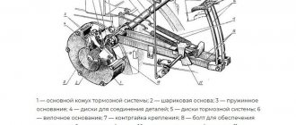
Rice. 2.3.10. Power steering (power steering): a - general view; 1 - amplifier housing; 2 - rail; 3 — power cylinder; 4 - piston; 5 - safety valve; 6 - spool; 7 - rotary shaft; 8 — upper cover of the power steering housing; 9 — adjusting bolt of the rotary shaft; 10 - sector; 11 — worm of the steering mechanism; 12 — differential lock sensor; 13 - drain pipe; 14 — steering bipod.
The main defects of the power steering include: wear of the worm shaft splines and sector teeth, gear rack, wear and violation of the tightness of the safety valve, wear and violation of the hydraulic tightness of precision parts (spools, plungers, sleeves). If, in the process of checking the technical condition of the units of the hydraulic steering control system of the tractor, faults are identified that cannot be eliminated by carrying out normal adjustment operations, the power steering is removed from the tractor and disassembled for technical examination and replacement of parts. The sequence of basic operations and the correct techniques for disassembling, assembling and adjusting the power steering are shown in Fig. 2.3.9 - 2.3.30.
Before removing the power steering, drain the hydraulic fluid and unscrew the steering shaft nut 4 .
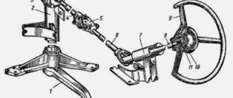
Rice. 2.3.9. Compressing the steering bipod: 1 - extension; 2 — steering bipod; 3 - drain pipe; 4 — rotary shaft nut.
Rice. 2.3.11. The relative position of the differential lock sensor parts: 1, 10 - bolts; 2 - cover; 3 - spring; 4 - spool; 5 - pusher; 6 - ring; 7, 9 — housings; 8 - valve; 11 - tap.
Rice. 2.3.12. Removing the oil supply tube from the distributor: 1 - oil supply tube; 2 — power steering housing; 3 - mesh filter; 4 - pressure reducing valve.
Rice. 2.3.13. Removing the rotary shaft: 1 — power steering housing; 2 - rotary shaft with a sector.
Fig.Fig. 2.3.14. Unscrewing the nut securing the sector to the rotary shaft.
Fig.Fig. 2.3.15. Pressing the sector from the rotary shaft.
Rice. 2.3.16. Removing the differential lock sensor.
Rice. 2.3.17. Removing the differential lock sensor cover.
Rice. 2.3.18. Removing the retaining ring and rack.
Rice. 2.3.19. Removing the power steering cylinder.
Rice. 2.3.20. Unscrewing the fastening nut and removing the piston.
Rice. 2.3.21. Removing the distributor.
Rice. 2.3.22. Removing the safety valve and worm assembly.
Rice. 2.3.23. Removing the worm bearing retaining retaining ring.
Rice. 2.3.24. Pressing worm bearings.
Rice. 2.3.25. Pressing out the rotary shaft bushing: 1 - bushing; 2 - axle; 3 — puller screw.
Rice. 2.3.26. Tightening the castle nut, worm nut.
The tightening torque is no more than 20 N.m.
When assembling the power steering, special attention is paid to the tightening torques of the nuts, the correct alignment of the marks of the rotary shaft, sector and rack, and the adjustment of the vertical movement of the rotary shaft.
Rice. 2.3.27. Alignment of marks on the end of the rotary shaft spline: 1 - marks; 2 - rotary shaft; 3 - sector.
Rice. 2.3.28. Combination of marks on the middle tooth of the secret shaft and the sector: 1 - marks; 2 - rail; 3 - sector.
Rice. 2.3.29. Tightening the piston nut.
Tightening torque 120N.m.
Rice. 2.3.30. Adjusting the vertical movement of the rotary shaft: 1 - adjusting bolt; 2 - lock nut.
Screw the bolt until it touches the rotary shaft, and then unscrew it 30 - 45° and secure it with a locknut.
Video on installing a dispenser on MTZ 80, 82
Over time, equipment components wear out, especially if the tractor has had several owners. The second possible reason is a large volume of air in the hydraulic system, which can lead to idle operation of the equipment.
Remove the O-rings and caps. All seals must be installed in place. Check valve - ensures the functioning of the metering pump in manual control mode as a hand pump when the power pump is not working.
Due to this, the bearings are constantly pressed against the ends of the gears, as a result of which gaps between the ends of the gears and the bearings are not allowed. The second cause of the problem may be abrasion of the sealing gaskets on the cylinders responsible for turning the machine. This crane provides the ability to lock the steering wheel on unstable road sections, which improves vehicle maneuverability. Dismantle the car worm.
Operating principle of the metering pump When the engine is running, oil is transferred to the metering pump thanks to the NSh oil pump. In the eyes of the housing and rod, spherical hinge bearings 7 are installed, which have channels on the inner ring for lubricating the friction surfaces through a grease nipple in the pin. The cover 11 contains a wiper 13, rod seals 14 and 15 and guide rings 16, which eliminate friction between the rod and the cover.
Description of the installation of the metering unit (GRU) of the MTZ tractor.
Tighten bolt 5. The kit also includes a pumping unit and a distributor.
There are also other malfunctions of the metering pump: When the steering wheel turns, the wheels of the car should, accordingly, turn. Holding filter 13 with your hand, turn out the pressure reducing valve and remove the drain filter. When the oil pressure in the drain hydraulic line drops below 0.08 MPa due to a lack of oil flow due to insufficient oil level in the oil tank, failure of the feed pump or broken hoses, the sensor is activated and the warning lamp for emergency reduction of oil pressure in the control lamp unit lights up. red hydraulic system. If the pump valves become clogged with dirt and other particles, they will not be able to move fluid through the system and regulate pressure. If one of them breaks down, oil is constantly supplied to one of the cylinders, and the steering wheel turns accordingly.
You can buy a ready-made pumping station, but it is better to assemble it yourself - in this case, it will work more efficiently since its elements will be selected in accordance with the tasks that need to be solved when organizing a water supply system. The piston is attached to the rod with a nut 2, which is locked by punching the collar into the grooves of the rod 6. Check the volume of oil and working fluid. This type of dispenser is equipped with a membrane, which acts as a wall through which the working fluid is absorbed and delivered to the required sections during the process of oscillation. How to convert the MTZ gur into a dispenser!
Read more: tractor clutch repair
Power steering (power steering) of the MTZ 82 tractor: repair and adjustment
The power steering of the MTZ 82 tractor is designed to reduce the effort exerted by the tractor driver on the steering wheel, regardless of operating conditions, as well as to improve the maneuverability of the tractor. While the tractor is moving, the power steering is activated not only by turning the steering wheel, but also by vibrations of the front wheels caused by uneven ground. At the same time, its impact is directed in the direction opposite to the rotation of the front wheels, which has a beneficial effect on the straightness of the tractor and reduces the transmission of shocks and vibrations from the front wheels to the steering wheel.
The hydraulic booster becomes important when operating speeds increase when operating a tractor with equipment mounted on it in front or on the side, when the load on the front wheels seriously increases, which requires considerable effort from the tractor driver to turn the tractor unit.
The power steering of the MTZ 82 tractor is equipped with its own hydraulic system, which consists of a distributor, a metering pump and a power cylinder, and also includes a sensor for automatic locking of the rear axle differential.
Power steering device
The steering mechanism is installed in the housing: a double-crown sector and a worm. The sector simultaneously engages with the worm and rack, connecting with a pin to the cylinder rod. The pin is mounted in the rod, but it is installed with a small gap in the holes of the rack ears. This solution allows the rack to move relative to the rod while adjusting the sector-rack engagement.
The worm is mounted on two radial ball bearings in an eccentric sleeve. The outer bearing races are installed in a bushing with a small gap to allow the worm to move in the axial direction together with the spool mounted on its shank. On both sides of the spool there are special thrust ball bearings that ensure axial movement of the spool and prevent it from simultaneously rotating with the worm. The bearing races directed towards the spool have large outer diameters and act as centering washers. A nut with a spherical end presses the bearings to the spool.
Power steering diagram of the MTZ 82 tractor: 1 - plug; 2 — valve cover; 3 — safety valve adjusting screw; 4 - worm; 5 — bolt of the adjusting sleeve; 6 — adjusting eccentric sleeve; 7 - sector; 8 - nut; 9 - rack; 10 — adjusting screw; 11 — top cover; 12 — oil line for lubrication of the upper support; 13 - filter; 14 - pressure reducing valve; 15 — control valve; 16 — sensor spool; 17 — crane handwheel; 18 — bipod; 19 - nut; 20 - drain plug; 21 - rotary shaft; 22 — body; 23 — rack stop; 24 — adjusting shims; 25 - rod; 26 - piston; 27 — front cylinder cover; 28 — thrust bearing; 29 - cover; 30 - nut; 31 - spool.
The rotary shaft, on which the bipod and sector are mounted on conical splines, rotates in three supports: in the top cover and two housing bushings. The upper support is lubricated by lubricant supplied through an oil line.
During straight-line movement of the tractor, the spool takes a neutral position and is fixed by three pairs of sliders placed at an angle of 120º. They are pushed apart by centering springs, as a result of which they tend to hold the internal bearing races associated with the spool at the same level with the ends of the distributor cover and the power steering housing. From the pump, the oil is supplied to the central belt of the spool and, since its width is less than the recess on the distributor body, it goes around it, enters the outer drain recesses and then through the pressure reducing valve and filter enters the tank - the power steering housing.
Diagram of operation of the power steering and differential lock: A - rodless cavity; B — rod cavity of the cylinder; 1 - pressure reducing valve; 2 — distributor cap; 3 - nut; 4 - spool; 5 - slider; 6 — centering spring; 7 - safety valve; 8 - filter; 9 - pump; 10 — eccentric bushing; 11 - worm; 12 - sector; 13 - bipod; 14 - rack; 15 — neck stop; 16 — locking cylinder; 17 — sensor oil line; 18 — crane handwheel; 19 — sensor tap; 20 - dipstick; 21 — sensor spool; 22 — power steering housing; 23 — rear cylinder cover; 24 - rod; 25 - piston; 26 — front cylinder cover; 27 — oil line of the blocking valve; 28 - rotary shaft.
Operating principle of the hydraulic booster
For example, let’s consider the tractor maneuvering to the right. The rotation of the steering wheel is transmitted to the worm through the steering drive. If the turning resistance of the front wheels is large, an axial force appears on the worm that exceeds the compression force of the centering springs. The worm is equipped with a right-hand spiral, therefore, when rotating to the right, it, relying on the sector slowed down by the resistance forces of the front wheels, will move together with the spool mounted on its shank forward, towards the cover (the maximum stroke of the spool in one direction is 1.2 mm, the stroke up to the moment overlap of the distributor housing belts - 0.6 millimeters). At the same time, the middle collar on the spool will block the flow of oil from the pump to the front drain groove. In this case, the outer flange of the spool will block the supply of oil from the cavity of cylinder B to the lower drain groove on the distributor body. The other outer flange of the spool will increase the cross-section for draining oil from cavity A of the cylinder into the recess on the distributor body. Oil from the middle discharge bore will flow through the oil pipeline into the cavity of cylinder B. The cavity B of the cylinder will increase, the piston, together with the rack and rod, will retract and, influencing the sector, turn the bipod and shaft to the left. The bipod, with the help of the steering linkage rod, will turn the front wheels of the tractor to the right.
The front wheels will turn to the right as long as the tractor driver turns the steering wheel. In this case, the speed of rotation of the wheels is proportional to the speed of rotation of the steering wheel. As soon as the steering wheel stops rotating, the spool will take a neutral position under the influence of the slider springs. The tractor is turned to the left in the same way.
Under normal operating conditions, the oil pressure in the hydraulic booster is 2-4 MPa (20-40 kgf/cm²). However, when the wheels are in the extreme position, when their further rotation is blocked by the piston stop in the cylinder cover, or when the resistance to turning the wheels increases due to extreme road conditions, the pressure in the system increases until the safety valve is activated. The oil, bypassing the cylinder, will drain under pressure into the drain line, on which a safety valve is installed. By tensioning the spring, the opening pressure of the safety valve is adjusted. It should be 8.3-9.3 MPa (83-93 kgf/cm²).
If there is practically no resistance to turning the front wheels (for example, when driving at high speed on asphalt), then the wheels are turned with little assistance from the power steering. In this case, the axial force on the worm, which appears when the tractor turns, is weaker than the pre-compression force of the centering springs of the sliders. Rotation of the steering wheel, connected to the drive using a worm, provides direct transmission of movement to the steering linkage through the sector, rotary shaft and bipod. In this case, the centering springs are not compressed, the worm along with the spool remains in place, and the oil in the distributor flows from the discharge cavity to the drain cavity without affecting the cylinder piston. In this case, the sector, with the help of a rack, moves the rod and piston of the cylinder, and the oil from cavities A and B is drained into the hydraulic distributor housing through open drain recesses.
In the event of transportation of a faulty tractor with a non-working diesel engine, a pump failure or other breakdowns of the power steering, control of the tractor remains available, but the force applied to the steering wheel will increase sharply.
Repair of power steering tractor MTZ 82
The main defects of the power steering are wear of the rack, sector teeth and worm shaft splines, leakage and wear of the safety valve, failure and violation of the hydraulic density of precision parts (sleeves, spools, plungers).
If, after a technical inspection of the condition of the power steering parts, faults are discovered that cannot be eliminated by normal adjustment operations, the power steering must be removed from the tractor and disassembled for further technical examination and replacement of parts.
Before dismantling the power steering, drain the working fluid and unscrew the steering shaft nut. During reassembly of the power steering, pay special attention to the tightening torques of the nuts, correct alignment of the marks of the rotary shaft, rack and bipod, and adjustment of the vertical movement of the shaft.
Disassembly, assembly and adjustment operations performed during power steering repair are quite complex and require special testing equipment.
The assembled power steering is tested on the KI-4896M stand. During the tests, the free play of the steering wheel is checked with the vertical power steering shaft fixed.
Unit design
When the oil pressure in the drain hydraulic line drops below 0.08 MPa due to a lack of oil flow due to insufficient oil level in the oil tank, failure of the feed pump or broken hoses, the sensor is activated and the warning lamp for emergency reduction of oil pressure in the control lamp unit lights up. red hydraulic system.
In the cover 6 there is a cuff 9, a wiper, rod guides 13, which eliminate friction between the rod and the cover, and rod seals.
The hinges are lubricated through grease fittings in the conical pins.
The technical dispenser pump will be in neutral if the system is not affected - in this case it will allow the liquid medium to pass directly towards the drain. Video on installing the dispenser on MTZ 80, 82 List of required parts: 1.
See also: Stalinist 80
Design and principle of operation of the dispenser
The basics of choice include mandatory consideration of productivity, operating pressure, liquid characteristics, concentration, viscosity, and density. The setting pressure of the anti-shock valves is from 20 to 21 MPa. The main features include the following factors.
Provides for the use of a planetary feedback gearbox. The hydraulic cylinder rod is connected through a conical pin 10 to the rotary lever 9 of the left wheel gearbox, and the hydraulic cylinder body is connected to a bracket 13 mounted on the FDA housing.
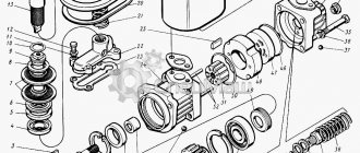
Steering dispenser MTZ 1 - cover; 2 - sealing ring; 3 - bearing; 4 — body; 5 - drive gear; 6 and 8 — cuffs; 7 — driven gear; 9 - plate. After the anti-shock valve is activated, oil is sucked into the cavity of the hydraulic cylinder. Do-it-yourself repair of the metering pump is mandatory, as mentioned above, in case of contamination of the hydraulic booster circuit system. Shock-type valve systems are needed to adjust the pressure level directly inside the highways; they are activated only in cases of heavy load, for example, on poor dirt roads.
Check valve - ensures the functioning of the metering pump in manual control mode as a hand pump when the power pump is not working. Also, such a picture will be observed when the air pump is pumped and the feed pump is poorly driven from the tractor engine. The hinges are protected from contamination by bushings 19 and protective rubber covers. Distributor II consists of a sleeve 5, a set of leaf springs 11 and a spool 3, which is connected by splines to the shank of the steering column drive shaft. Steering column MTZ modernization