Specifications
| Model | SMD-31A |
| Rated power, kW (hp) | 173 (235) |
| Operating power, kW (hp) | 165,6 (225) |
| Rated rotation speed, rpm | 2000 |
| Minimum stable idle speed, no more than rpm | 800 |
| Maximum idle speed, no more than rpm | 2130 |
| Specific fuel consumption at rated power mode, no more than g/kWh (g/hp.h) | 224 (165) |
| Specific fuel consumption at operating power mode, no more than g/kWh (g/hp.h) | 234 (172) |
| Oil pressure in the main line of the diesel lubrication system at steady state operating mode and coolant temperature 80–95°C MPa (kgf/cm2): - at rated speed - at minimum stable idle speed, not less | 0,3–0,55 (3–5,5) 0,1 (1,0) |
| Starting system | Electric starter 3212.3708 and electric torch heater EFP-8101500 |
| Diesel design weight according to GOST 20000, kg | 1050–1100 |
Engine characteristics
The Kharkov plant became the first platform on which the production of the SMD engine was launched back in 1958. This mechanism has become one of the most popular parts used for assembling tractors, cultivators and combines. At the beginning of the 2000s, the production of SMD motors was suspended due to the appearance of more advanced analogues on the equipment market.
Engine SMD-18
The range of such engines is represented by the following options:
- 4 cylinder engine
- 6 cylinder combination
- V-shaped mechanisms with 6 cylinders
Motors of this configuration have been supplanted by more current models, but their technical parameters are quite competitive in the world of modern units. Technical characteristics of SMD engines are presented by the following indicators:
Fuel pump for SMD-18 engine
- Maximum power – 100 hp.
- Operating power – 95 hp.
- Average rotation speed – 1800 rpm
- Idle rotation - 600 rpm
- Cylinder volume – 9.15 l
- Number of cylinders – 6 pcs.
- Fuel consumption – 164 g/l.h.h.
- Cylinder rotation angle – 90o C
- Cylinder radius – 165 mm
- Total weight max – 880 kg
- Liquid temperature in the cooling system max – 95o C
The engine is also equipped with a liquid cooling system and a remote start function, carried out using a P-10 UD starting apparatus with an RPD 1,000 M gearbox. The device is distinguished by the presence of a forced ventilation system. The closed cooling circuit is charged with water, which is distilled through the arteries of the system using a water pump.
Starting motor PD-10UD
The description of the SMD-18 engine implies that this mechanism is a powerful system with automatic fuel spraying. The SMD model includes a special part - a crankcase, which is responsible for rigidity and resistance to external pressure.
Kharkov Tractor Engine Plant
| content .. 10 | |
| Kharkov Tractor Engine Plant | |
| Type | public corporation |
| Base | 1965 |
| Location | USSR → Ukraine, Kharkov st. Kyrgyzskaya, 19 |
| Industry | agricultural engineering |
Kharkov Tractor Engine Plant
(
KhZTD
) is a machine-building plant for the production and repair of diesel engines and power plants.
Content
- 1. History
- 2 Activities
- 3 Technological characteristics 3.1 Production structure 3.1.1 Main
- 3.1.2 Auxiliary
History [edit | edit code]
The plant was designed and built for an annual production of 125 thousand engines. During the period of operation of the plant, the maximum annual production was 86 thousand engines.
After the declaration of independence of Ukraine, the Ministry of Mechanical Engineering and Military-Industrial Complex of Ukraine decided to transform the state enterprise KhZTD into OJSC "Kharkov Tractor Engine Plant" (at the same time, 72.18% of the plant's shares remained in state ownership, 26% of the shares were transferred to management state leasing, individuals owned 1.82% of shares).
In 1994, the KhZTD plant began production of the SMD-900 diesel engine [1].
In recent years, the actual level of HZTD production has decreased to 12-16% of the approved capacity, which was the result of a decrease in consumer demand due to the general decline in economic development in Ukraine, high production costs due to rising prices for energy resources, technological raw materials and materials, as well as high saturation of the Ukrainian market with foreign-made diesel engines.
In 2001, the plant began production of the SMD-63 engine.
In 2001, the plant produced only 450 engines. Subsequently, high production costs, the transition to barter payments with contractors, a decrease in production volume, and huge costs associated with the maintenance of social facilities (kindergartens, a hospital, a clinic, residential buildings and dormitories of the plant) led to the bankruptcy of the enterprise. At the beginning of May 2002, KhZTD was officially declared bankrupt (by this time about 1.5 thousand people continued to work at the company) [2].
The way out of this critical situation was judicial reorganization, the decision to carry out which was made by the plant’s creditors.
In 2004, a special design and technological bureau “Gidromodul” was located in the unused production premises of KhZTD [3].
On April 19, 2005, in accordance with the decision of the economic court of the Kharkov region, a liquidation commission was created for KhZTD [4].
On May 17, 2005, the economic court of the Kharkov region approved the decision to liquidate KhZTD OJSC [5].
At the beginning of April 2007, a decision was made to sell the plant [6].
On July 18, 2007, the State Property Fund of Ukraine decided to sell the state stake in KhZTD [7].
In the fall of 2007, more than 50% of the shares of OJSC KhZTD were acquired by CJSC Business - a company whose main activity was leasing its own and state real estate for non-production purposes [5].
In December 2007, the first Buddhist pagoda in Ukraine was opened on the territory of the plant [8].
By 2008 [9], the plant ceased to exist [10], however, the buildings and infrastructure of the plant continued to be used (for example, the KhZTD electrical substation became the property of Energoresurs LLC) [11].
A shopping and entertainment center was built on the territory of the plant [12].
Activities [edit | edit code]
The plant specialized in the production of turbocharged diesel engines SMD-60 for T-150 tractors and KS-6B combines. Based on the SMD-60 engines, SMD-62 engines (165-240 hp) were developed and produced, which were used as power plants on tractors and self-propelled forage and beet harvesters and other machines. The plant also mastered the production of diesel engines with a capacity of 18-36 hp. pp., diesel electric generators with a capacity of 8 and 60 kW. In addition, OJSC "KhZTD" produced spare parts for these engines, and also carried out major and preventative repairs of engines.
Among the consumers of the products produced by the plant were the Kharkov Tractor Plant, Ternopil and Kherson Combine Harvester Plants, Ivano-Frankivsk, Kharkov Self-Propelled Chassis Plant,. A significant number of engines and spare parts for them were supplied to agricultural enterprises for the restoration of agricultural machinery already in use.
Technological characteristics [edit | edit code ]
The plant was a mechanical assembly enterprise, the technological process of which involves such types of production as mechanical assembly, assembly, cold stamping, thermal production, electroplating, welding and painting production.
The technological equipment is dominated by automatic lines, metal-cutting, forging, woodworking, hoisting and transport, thermal and other equipment, specialized and modular machines, automatic and semi-automatic machines.
All main and auxiliary production facilities are compactly located on one production area with an area of 34.96 hectares, the total area of industrial buildings is 280,718 m², all production facilities have a single engineering infrastructure and railway access tracks.
General information
The SMD motor line includes the following motors:
- four-cylinder in-line;
- six-cylinder in-line;
- units with six cylinders are V-shaped.
It is also important to note that any of these motors are highly reliable. This parameter is ensured due to correctly adopted design decisions, which, even by today’s standards, may well ensure a long service life of this motor. To date, the production of this type of units has been established at the Belgorod Motor Plant.
Failures in tractor engines - signs, causes, repairs.
In this article we will look at failures in tractor engines and their causes, and talk about how to fix breakdowns. We will look at tractors that use a diesel engine as a power plant. We have to face the fact that farmers, machine operators and heads of engineering services of a number of farms still do not know enough about the structure, design and operational features of these diesel engines.
Considering cases of engine failure in various regions of the country, most often you come to the conclusion that engine failures are caused mainly by violations of technical operation rules.
During the operation of engines, we have accumulated extensive experience in quickly and accurately identifying the causes of malfunctions and ways to eliminate them.
Such violations include:
- emission of crankcase oil through the engine exhaust pipe and flywheel housing,
- increased oil consumption,
- appearance of oil in fuel and water,
- the appearance of knocking in the engine and others.
What are the consequences of different blood pressure?
Car enthusiasts more often encounter cases of unacceptably low pressure in the engine, so we will first consider this problem.
Dangers of Low Engine Pressure
If the pump does not provide sufficient pressure, the engine experiences oil starvation. A sufficiently strong lubricating film does not form on the surface of the friction pairs, which leads to increased wear. Insufficient oil pressure also leads to malfunction of hydraulic compensators.
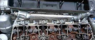
Gas distribution mechanism for diesel engines SMD-23-24-31
Gas distribution mechanism of diesel engines SMD-23-24-31.
The gas distribution mechanism is designed to admit fresh air into the cylinders and release combustion products. It consists of a camshaft, timing gears, intake and exhaust valves, and fasteners.
The diesel camshaft SMD-31 is steel, four-bearing, SMD-23 is three-bearing. The surfaces of the necks and cams are hardened with high-frequency high frequency.
The SMD-31 diesel engine has an annular groove on the middle journals of the camshaft through which oil is supplied to the valve mechanism. In the SMD-23 diesel engine, a channel is drilled on the last journal of the camshaft to supply oil to the valve mechanism.
The camshaft is driven through an intermediate gear, which meshes with the gears of the crankshaft and the fuel pump. To ensure correct assembly, the gears are marked P (camshaft), K (crankshaft), T (fuel pump). When assembling, the marks must be aligned.
Rice. 14. Camshaft and valve mechanism of the SMD-31 diesel engine: 1 – camshaft; 2 – inlet valve; 3 – valve plate; 4 – cracker; 5 – rocker axis; 6 – rocker arm; 7 – retaining ring; 8 – plug; 9 – nut; 10 – adjusting screw; 11 – plate bushing; 12 – internal valve spring; 13 – external valve spring; 14 – inlet valve; 15 – push rod; 16 – pusher; 17 – thrust bearing; 18 – camshaft gear; 19 – pin; 20 – washer; 21 – bolt
Rice. 15. Camshaft and valve mechanism of the SMD-23 diesel engine: 1 – camshaft gear; 2 – camshaft; 3 – inlet valve; 4 – valve spring plate; 5 – bushing; 6 – valve holder; 7 – bushing of the rocker arm axis; 8 – spacer spring; 9 – exhaust valve; 10 – internal valve spring; 11 – external valve spring; 12 – push rod; 13 — pusher; 14 – roller of the decompression mechanism; 15 – rocker axis; 16 – stand of rocker arm rollers and decompression mechanism; 17 – idler pin; 18 – adjusting screw; 19 – lock nut of the adjusting screw; 20 — valve rocker arm; 21 – retaining ring; 22 – decompression mechanism housing; 23 – intermediate gear; 24 – washer; 25 – bolts for fastening the intermediate gear; 26 – lock washer; 27 – camshaft gear mounting bolts
The camshaft cams support the pushers, which perform a reciprocating motion during operation, and the cam. The pushers contain rods made of steel rod. The sphere of the rods is hardened by high-frequency high frequency. During operation, the rods move rocker arms, which open valves that close under the influence of springs. Valve springs are secured to the valves using a plate, bushing and block.
Rice. 16. Gear wheels for the distribution of the gas distribution mechanism of the SMD-31 diesel engine: 1 – gear driven wheel for the oil pump drive; 2 – gear drive wheel of the oil pump drive; 3 – crankshaft gear (drive); 4 – gear wheel of the NSHYUE-Z-L pump drive; 5 – camshaft gear; 6 – gear (intermediate); 7 – fuel pump drive gear
Rice. 17. Diesel distribution gears of type SMD-23: 1 – gear driven wheel of the oil pump drive; 2 – gear drive wheel of the oil pump drive; 3 — pump drive gear NSh50U-2L (or NSh32-2-L); 5 – gear wheel of the NSHYUE-Z-L pump drive; 6 — camshaft gear; 7 – intermediate gear; 8 – fuel pump drive gear
In the SMD-31 diesel engine, there are three rocker arm axles on each cylinder head (with two rocker arms on each axis). The axial movement of the rocker arms is limited by locking rings. The SMD-23 diesel engine has one rocker axis.
The valves are made of heat-resistant steel, and the guide bushings located in the cylinder heads are cermet.
Maintenance of the gas distribution mechanism consists of periodically checking and, if necessary, adjusting the gap between the rocker arm striker and the ends of the valve stem, carried out every 480 operating hours.
The nominal clearance for the intake and exhaust valves of a cold diesel engine is 0.4…0.45 mm.
When checking and adjusting the clearances of diesel engines SMD-23 and SMD-31, install the piston of the first cylinder in i.e. m.t., for which, rotating the crankshaft clockwise, observe the valves of the first cylinder. They should open and then close. Continuing to slowly turn the crankshaft, align the mark in. m.t. on the flywheel with an indicator mark on the flywheel housing (Fig. 18). With this position of the valves, check and, if necessary, adjust the clearance. To perform the operation, use a 17x19 wrench, a 12x14 socket wrench, a screwdriver and a No. 2 or 3 feeler gauge.
Adjust the clearances of the remaining valves in the sequence of operation of the diesel cylinders (SMD-23: 1-3-2-4; SMD-31: 1-5-3-6-2-4), turning the crankshaft of the SMD-23 diesel engine half a turn, SMD-31 – at 120°.
Rice. 18. Index c. m.t. on the flywheel housing and the scale on the flywheel of SMD-31 diesel engines: 1 – mark (pointer) c. m.t. on the flywheel housing; 2 – mark c. m.t. on the flywheel; 3 – flywheel housing; 4 – flywheel crown; 5 – flywheel scale
Rice. 19. Checking and adjusting the gap between the valve stem and the rocker arm: 1 – head; 2 – rocker arm; 3 – control nut; 4 – adjusting screw; 5 – valve
Rice. 20. Installation of a stud on the flywheel housing of an SMD-24 diesel engine (with starting from a starting engine) to determine the crankcase. m.t.
On an SMD-24 diesel engine, after opening and closing the valves, it is necessary to unscrew the pin from the flywheel housing, install it with the reverse (non-threaded) part in the same hole and, slowly continuing to rotate the crankshaft, align the pin with the hole in the flywheel (Fig. 20). With this position of the valves, check and, if necessary, adjust the clearance. Adjust the clearances of the remaining valves in the sequence of operation of the diesel cylinders (1-3-2-4), each time turning the crankshaft clockwise half a turn.
Lubrication system diagrams
For the SMD-14 diesel engine, oil is poured into pan 15 (Fig. 151) through the filler neck with a filter mesh. Its level in the pan is controlled by marks on the oil gauge. The oil is drained through a hole in the pan, closed with a plug.
From the crankcase sump 15 , oil is sucked through the oil receiver mesh 1 by gear pump 3 and supplied through channels in the crankcase to filter 9 - a full-flow centrifuge. In it, a small part of the oil passes through the rotor nozzles and creates a reactive torque that rotates it at high speed. Then this oil is drained through channel 14 into the oil pan 15 . The other part of the oil is subjected to centrifugal cleaning and, through switch I, enters radiator 8, in which it is cooled.
The cleaned and cooled oil is sent to channel 4 (main line), running along the crankcase. From the main line 4 , through channels in the transverse partitions of the crankcase, oil reaches the main bearings. From them, part of the oil flows through inclined channels in the shaft into the cavity of the connecting rod journals. In these cavities, additional (centrifugal) purification of the oil occurs, which then lubricates the rubbing surfaces of the bearings and connecting rod journals.
The oil, removed by the oil scraper rings and flowing into the oil pan, as well as squeezed out of the gaps of the main and connecting rod bearings, is sprayed by the rotating crankshaft. The resulting oil mist lubricates the rubbing surfaces of the cylinder liners, pistons, piston pins and bushings of the upper connecting rod heads,
The camshaft bearing journals are lubricated by oil supplied through channels in the transverse partitions of the crankcase or the first, third and fifth main bearings.
An inclined channel is made in the third journal of the camshaft, which once for each revolution connects the hole supplying oil to this journal with vertical channel 16 in the crankcase and with its continuation - channel 7 in the cylinder head. This makes it possible to supply oil in a pulsating flow through tube 6 into the internal cavity of the rocker arm rollers and from it through the holes in the rollers to the rocker arm bushings. The oil flowing from the rocker arm bushings and sprayed by the moving coils of springs lubricates the rubbing surfaces of the rods, adjusting bolts and valves. The oil flowing down the rods into the oil pan hits the rubbing surfaces of the pushers and camshaft cams and lubricates them.
Oil is supplied to the intermediate gear bearing from a channel in the first transverse partition of the crankcase through drilling in the gear axis. From the main oil line, through a tube and then through channels in the wall of the timing gear housing and the mounting flange, oil flows to the rubbing surfaces of the fuel pump drive gear bushing and the cylindrical part of the mounting flange.
The bearings of the water pump and generator are periodically lubricated through grease fittings.
The teeth of the camshaft gears are lubricated by oil coming from the radial holes in the idler gear axle and body, as well as by oil flowing from the front camshaft bearing and the fuel pump drive gear bushing.
To monitor the oil pressure and temperature in the main line, a pressure indicator and a remote temperature indicator are installed on the control panel.
The normal oil temperature in a diesel engine loaded at full power should be in the range of 80–95° C. At this temperature and the nominal speed of the diesel crankshaft, the oil pressure should be 0.25–0.45 MPa. The minimum oil pressure in the system is allowed below 0.08 MPa.
The lubrication system has three automatically operating valves: oil pump pressure relief, safety and drain.
Reducing valve 2 transfers oil from the discharge cavity of the oil pump to the oil pan when the oil viscosity is increased (for example, when starting a cold diesel engine). The valve is adjusted to a pressure of 0.7-0.8 MPa.
Safety valve 10 transfers oil directly into the main oil line 4, past filter 9, when the filter is heavily soiled and when the oil viscosity is high. The valve is adjusted to a pressure drop of 0.30–0.45 MPa.
Drain valve 12 transfers oil to the oil pan when the oil pressure in the main line 4 is above 0.25-0.45 MPa.
In winter, if, with the radiator shutter closed and the diesel engine running at full load, the oil temperature drops below 75° C, radiator 8 must be turned off by changing the position of switch 11. In this case, the switch pin comes out.
The combined lubrication system with a full-flow centrifuge described above is typical for the SMD-60, D-50, D-240, D-37E, D-21, ZIL-130, A-41, A-01M engines.
For diesel engines A-41 and A-01M, the gear pump is divided into two sections: the main (discharge) and radiator. The pressure section supplies oil to the main line through a full-flow centrifuge, and the radiator section supplies oil directly to the radiator for cooling.
To ensure the supply of oil to the lubrication system before starting, SMD-60 diesel engines are equipped with a gear pump for pre-starting oil pumping. The drive gear of this pump is in constant mesh with the starting motor gear. After starting the latter, the pump supplies oil from the oil pan through a special valve into the main line of the diesel engine. When the diesel engine starts working, the valve blocks the access of oil from the crankcase to the pump.
Maintenance of SMD 60/62 engines
It is recommended to use special brands as lubricating fluids for tractor engines of these models. In summer it is M10G engine oil, and in winter it is M8G. If you are unable to purchase the recommended liquids, you can temporarily use substitutes:
- summer motor lubricant – M 10B;
- winter diesel oil - DS-8.
Attention: When using analogues, you need to switch to fuel with a reduced sulfur content (no more than 0.5%).
Air leak in the tractor engine power supply system.
Failures in tractor engines also occur due to air leaks in the power system . Air leaks in the engine power supply system can occur due to cavities and irregularities in the places where the fuel pipes are attached, as well as due to a failure of the mechanical pumping of the fuel pump. If the air is removed by manual pumping, but the engine stalls after 1-2 minutes, it means that the injector nozzle needle is stuck.
There may be cases when gases, along with excess fuel, enter the filter bracket, and from there into the fuel system. This malfunction is determined by disconnecting the fuel outlet pipe from the filter bracket. When air leaks, remove the injectors and check the spray quality and injection pressure.
Cost and reviews of the SMD engine
It is worth noting that the cost of these engines is very low. It cannot be compared with imported analogues. All components for these units that may be needed during repairs are also low in cost. It is also worth noting that, despite the long break in the production of these models, there are a lot of spare parts for them and they are not difficult to find, since previously too many of these engines were produced.
However, it is worth noting that their low cost is not for nothing. Reviews about the SMD-21, for example, are not the most pleasant. Despite the fact that major repairs were carried out once a year, the maximum speed was only 80 km/h when driving downhill and the clutch was depressed, and if not depressed, then 60 km/h. The owners also said that vibration in the engine constantly caused everything to spin up. The only plus that stood out from user reviews was fuel consumption, which was only 20 liters per 100 km.
Device SMD-14
The design of the motor is quite simple and allows for the possibility of changing its power, which is especially convenient when performing various tasks with its help. To do this, you will need to adjust the engine in accordance with the standard algorithm specified in the instructions for it. It is advisable to include the following structural elements among the main components of SMD-14:
- starting motor PU101-U;
- starter - SG352;
- a generator capable of operating with or without a battery;
- protective equipment - spark arrestors;
- lubrication system, including drain, bypass and safety valve;
- filter elements;
- cooling system.
The fuel system of the unit also deserves mention, which provides the ability to wash the filters without disassembling it, which makes maintenance simple and convenient. It should be mentioned that the design of the motor has been improved several times. This led to the emergence of new generations of SMD, as well as the 14NG modification, which is characterized by greater power and improved performance.
Engines SMD-31
Six-cylinder, four-stroke diesel engines are equipped with turbocharging.
The power of the SMD-31A is 235 horsepower. The main application is the DON-1500 combine.
SMD 31.16 was created for the Slavutich combine produced by Kherson, its power is 265 hp. With.
SMD 31.20 – “Obriy”, the combine harvester is manufactured in Kharkov. Engine power – 230 hp. With.
Technical characteristics of the SMD 31 engine:
- crankshaft rotation speed – 800 – 2130 rpm;
- fuel consumption from 165 to 172 g/l.h.;
- the starting system is equipped with an electric starter 3212.3708, as well as an electric torch heater EFP 8101500;
- assembled motor weight – 1050 – 1100 kg.
Description
SMD-14, as can be seen in the photo, has several important differences from most analogues used in specialized vehicles. It is necessary to mention its compact dimensions, as well as its light weight, which greatly simplifies the maintenance and repair of the power unit.
A distinctive feature is quite powerful performance indicators, which can be adjusted if necessary, which is extremely important for the agricultural industry. Other important characteristics include:
- availability of a protection system;
- ease of maintenance of the fuel system;
- presence of a starting motor;
- 2 generator operating modes.
Such innovations, compared to previous models of the concern, allowed the SMD-14 to quickly replace outdated predecessors and become one of the most popular power units.
Engine Specifications
As mentioned earlier, the performance of the motor made it incredibly popular among manufacturers of agricultural machinery. A large number of spare parts, as well as the low cost of this type of device, make it a profitable and reliable solution, especially in comparison with numerous foreign analogues.
The most important operating parameters of the SMD-14 engine include:
- total power - 75 hp;
- rotation speed - 1800 rpm;
- fuel consumption level - 218g/kWh;
- number of cylinders - 4 pcs., diameter 120mm;
- piston stroke - 140mm.
The model’s performance, combined with a successful design and long service life of the unit, allows us to call it one of the most popular at the time of release.