Gearbox of Kirovets K-700, K-700A, K-701 tractors. Main components.
As we have already said HERE, all transmissions for the Kirovets tractors of the K-700, K-700A and K-701 models have a mechanical drive for mode switching and hydraulic control of the clutches.
In other words, the modes are switched on like gears on a conventional (mechanical) box by moving the gears, and the gears in the K-700a, K-701 and K-700 gearboxes are switched through hydraulic control of the drive shaft clutches.
Thus, within any mode, gear shifting is ensured without interrupting the power flow. The K-700 gearbox, the K-700A gearbox and the K-701 gearbox are not fundamentally different.
As stated in the 1986 textbook: “The transmission of the K-700, K-700A and K-701 tractors is mechanical, with constant mesh gears, 16-speed, (four-mode), with hydraulic control of four clutches and mechanical control of gear clutches. All gears are spur gears.
The number of teeth and gear engagement modules are shown in the kinematic diagram of the transmission in the figure below:
HERE you can find out which gears (gear shafts) and with what number of teeth are installed in various gearbox models of Kirovets K-700A, K-701 and others tractors.
By the way, due to the fact that all the gears in the Kirovts gearboxes are straight-cut (except for one small bevel pair), there is practically nothing to rattle or knock in the tractor gearbox. Therefore, if you can hear “heavenly thunder” from your Kirovets K-700A, K-701 tractor box, then it’s time to disassemble or change it. This won't end well.
The gearbox on Kirovets tractors is installed on the front semi-frame on four shock absorbers 700.00.17.170 (AKSS-220M). The horizontal position of the gearbox of the K-700A and K-701 tractors is achieved through the use of adjusting shims 700A.00.17.098-1 and 700A.00.17.098-2. The Kirovets box is supported by four brackets (legs) on the shock absorbers.
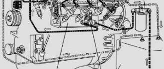
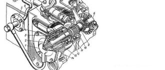
The general view of the checkpoint is shown in the figure below. Because this picture is quite old, it shows a view of the K-700 tractor box. The 700A gearbox looks a little different.
The gearbox housing of the Kirovets K-700, K-700A, K-701 tractors is made from cast iron. It consists of the upper half of cat. number 700A.17.01.256-1 (No. 18 in the figure) and the lower half of cat. number 700A.17.01.255-2 (No. 16 in the figure). Both parts have an internal partition that serves as a support for the drive shaft of the gearbox 700А.17.01.010 and the drive shaft of the gearbox pumps 700А.17.01.191, in addition, inside the lower half of the crankcase there is a cast bracket for installing the reverse gear axis 700.17.01.138-02 700.17.01.075 tractors K-700A, K-701.
On the upper half of the gearbox housing, a breather is installed, a gear shift mechanism (item 8) 700A.17.02.000-2 with a valve box and lever (item 7), a bridge (item 2) 700A.17.19.500-2 control drives with drain pedal (item 3) 700.00.17.077, gearbox linkage (item 1) 700A.17.17.000 with lever 700A.17.17.020 for controlling the gear couplings of the cargo shaft (item 6).
In the lower half of the crankcase, rollers and a pin with forks are installed, with the help of which the gear couplings of the pump drive shaft, cargo and transfer shafts are controlled. Two housings (item 13), a plate (item 14) and a stamped steel pan 700A.17.04.010 (item 15) are attached to the lower half of the crankcase. The gearbox oil pump with an oil intake is placed on the plate. The photo shows the transmission pan K-700a cat. number 700A.17.04.000.
When any gear, forward or reverse clutches and the transfer shaft clutch are engaged, torque is transmitted from the drive shaft to the intermediate shaft, load shaft, transfer shaft and through the propeller shaft to the front drive axle, and when the clutch is engaged - to the shaft and through cardan shafts and intermediate support - to the rear drive axle. The intermediate shaft can rotate at four different speeds, the load shaft can rotate at eight different forward speeds and four in reverse, and the transfer shaft and shaft can rotate at sixteen different forward speeds and eight in reverse.
The gearbox of the K-702 tractor, like the gearbox of the K-700A and K-701 tractors, is mechanical, multi-shaft, friction, with constant mesh gears, mechanical switching of modes and hydraulic switching of forward and reverse gears within each mode.
Almost all parts in the gearbox are unified. It differs mainly in the number of gears (four forward, instead of sixteen, and four reverse, instead of eight), the number of modes (two instead of four), the number of intermediate shafts (two instead of one) and oil filters (two instead of one) and the pump shaft drive device (from the torque converter pump wheel, not from the drive shaft).
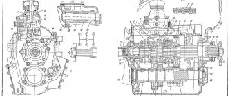
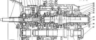
Rice. 1. Gearbox of tractors K-700A and K-701 (section along the shafts): 1 - drive shaft; 2, 3, 4, 6, 7, 8, 10, 13, 17, 19, 21, 22, 23, 24, 27 and 29 - gears; 5 — intermediate shaft; 9 — load shaft; 11, 12 and 75 - transfer shaft couplings; 14 - transfer shaft; 16 – shaft; 18 and 20 — cargo shaft couplings; 25 — worm gear of the tachospeedometer drive; 26 — pump drive shaft; 28 — coupling; 30 — pump drive shaft; 31 - bevel gearbox.
Each intermediate shaft can rotate at two different speeds, the load shaft can rotate at four (two for forward and two for reverse), and the transfer shaft can rotate at eight (four for forward and four for reverse).
The torque converter of the K-702 tractor is single-stage, complex, four-wheeled. The parts of the semi-rigid coupling are unified with similar parts of the K-700 and K-700A tractors. The drive disk is mounted on the engine flywheel. Torque from the engine to the gearbox is transmitted through the drive disc, shock absorbers, pins, driven disc, gear coupling, drum hub, drum to the pump wheel and then to the turbine wheel and through the hub to a shaft connected by a driveshaft to the drive shaft of the gearbox.
The drive of the hydraulic pumps of the steering and hitch control hydraulic systems, as well as the gearbox oil pump, is independent. They are driven by a gear mounted on a cup (pump wheel hub), through gears, a compensating device and a shaft. The guide vane wheels are connected to the fixed hub through roller-type freewheel couplings. The direction of the flow of working fluid flowing from the turbine wheel during the transition from low to high rotation speed changes so that the freewheel clutches in the first case hold the wheels of the guide vanes in a stationary position, and in the second case they release them, and the latter rotate freely than provides a transition from torque converter mode to fluid coupling mode. Thanks to this property, the torque converter is called complex. The torque converter mode is used when starting the tractor, accelerating and driving in difficult road conditions. The fluid coupling mode is used to reduce the external load and equalize the torques of the pump and turbine wheels.
The pressure of the working fluid is regulated by the make-up valve. It maintains a pressure of 350...380 kPa (3.5...3.8 kgf/cm2) at the outlet of the torque converter, which is sufficient to ensure cavitation-free operation and drain part of the oil when the pressure rises above 750 kPa (7.5 kgf/cm2).
—
Type, general device. The tractor's gearbox is mechanical, multi-stage, with constant mesh gears, hydraulically controlled gear clutches and a mechanical drive for switching modes using gear clutches.
The transmission housing consists of an upper half, a lower half, a spacer and a pan. On the upper half of the crankcase are installed: a hydraulic system gear shift mechanism; hydraulic system filter; a rocker with levers for engaging the clutches of the transfer shaft, cargo shaft and reverse shaft, as well as a lever for disabling the rear axle; control drive bridge; brake-synchronizer; two hydraulic pumps for attachments; steering hydraulic system pump and breather 4, which ensures communication between the internal cavity of the crankcase and the atmosphere.
Rice. 2. Gearbox (general view): 1 — pump for the hydraulic system of attachments; 2 — backstage; 3 — bridge of control drives; 4 — breather; 5 — rear axle release lever; 6 — brake-synchronizer; 7 — gear shift mechanism of the hydraulic system; 8 — pump of the steering hydraulic system; A, B - backstage levers; C - gear shift lever
Rice. 3. Gearbox (shaft drive):
Based on the functions they perform, gearbox mechanisms can be divided into the following groups. 1. A gear part that transmits torque from the engine to the axles and drives the pumps of the hydraulic steering control systems of the tractor, attachments and the gearbox hydraulic system. 2. The hydraulic system of the gearbox and power take-off mechanism, which provides control of the gear clutches and lubrication of the gearbox components, semi-rigid clutch and power take-off coupling. 3. Gearbox control mechanisms.
Gearbox part. It consists of a drive shaft with friction clutches, an intermediate shaft, a load shaft, a transfer shaft and a pump drive shaft.
The drive shaft rotates on two roller bearings and one ball bearing. There are four clutches and five spur gears on the shaft. The gear is the drive gear of the pump drive shaft. The drive shaft is hollow and has two oil lines that supply oil to the clutches. The oil supply to the clutches is carried out from the middle support of the drive shaft.
The gearbox clutches are multi-disc with sulfocyanated steel discs. Each clutch consists of driving and driven parts and an activation mechanism. The leading parts include: the driving, or internal, drum, driving friction disks, a pressure disk with springs and cups; to the driven parts of the clutch - the driven, or outer, drum and driven friction disks.
The actuation mechanism includes a middle disk with o-rings, o-rings with cuffs and a ring.
The driving parts of the clutches are connected to the drive shaft, which constantly rotates at the engine speed. The driven parts of the clutches are connected to freely rotating gears.
The clutch is activated by oil pressure entering the booster - the space between the middle and pressure disks. Moving under oil pressure, the pressure plate compresses the friction disk pack, and torque from the drive shaft is transmitted to the gear connected to the driven drum, and then to the intermediate shaft.
Some of the oil enters the cavity of the inner drum through the hole in the pressure disk and then goes through the holes in it to lubricate the friction disks.
When the clutch is turned off, the pressure plate I returns to its original position under the action of cylindrical springs,
Rice. 4. Gearbox clutch (a) and diagram of its operation (b): 1 - cast iron sealing rings; 2 — sealing rubber ring; 3 - locking screw; 4 - drive shaft; 5 – cuff; 6 – plug; 7 – ring; 8 – sealing ring; 9 — middle disk; 11 — pressure disk; 12 — outer drum; 13- inner drum; 14 – spring; 15 — glass; 16 — driving friction disk; 17 — driven friction disk; 18 — off; 19 - included
The intermediate shaft has three supports - two roller bearings and one ball bearing. There are seven gears installed on the shaft splines, four of which are in constant engagement with the drive shaft gears, two with gears that rotate freely on the load shaft, and one with the reverse idler gear.
The load shaft rotates on two roller bearings and one ball bearing. The shaft is equipped with five spur gears and two toothed couplings. The gears are mounted on two ball bearings and have both external and internal teeth. The gear is connected to the intermediate shaft gear through an idler gear. The gears are in constant mesh with the intermediate shaft gears. Gear couplings are located on splined bushings. The gears are mounted on the shaft splines and mesh with the transfer shaft gears.
The transfer shaft is double-bearing. Installed in the gearbox housing on a roller bearing and ball bearing. The shaft has two gears and two toothed couplings.
Inside the transfer shaft there is an annular bore into which the shaft journal is mounted on needle bearings. On its outer splined surface there is a rear axle disengagement clutch.
When the drive shaft rotates, the drive clutch drums sitting on its splines rotate. When the clutch is engaged, rotation is transmitted to the driven drum and the gear attached to it, which is in constant engagement with the intermediate shaft gear. The clutch gears differ from each other in the number of teeth.
Depending on the engaged clutch, the intermediate shaft receives a certain rotation speed. From the intermediate shaft, through gears and a gear coupling, a load shaft is driven, the rotation speed of which varies depending on the position of the gear coupling. When moving it along the shaft splines to the left, the clutch engages with the gear, and when moving it to the right, it engages with the gear.
Changing the direction of rotation of the cargo and transfer shafts (reversing the tractor) is carried out using a gear, an idler gear and a gear coupling.
The rotation speed of the transfer shaft is changed by a gear coupling, which has two positions.
Thus, when one of the clutches is engaged, it is possible to make two gear clutch switches on the load shaft and two on the transfer shaft.
The gearbox has forward and reverse speeds.
Rice. 4. Direction of power flows in various modes and gears
The drive shaft of the hydraulic steering control system pumps of the tractor, attachments and gearbox is installed in the connector of the upper and lower halves of the crankcase parallel to the drive shaft of the gearbox. There are two drive gears on the shaft. The connection of the gears to the drive shaft is carried out by a gear coupling. With its external teeth it can engage with the internal teeth of the drive gears, and with internal splines through an intermediate sleeve it is rigidly connected to the shaft.
The gear coupling has two positions. When it meshes with the gear, the shaft receives rotation from the transmission drive shaft. When the clutch is engaged with the gear, rotation is transmitted to the shaft through the reverse idler gear from the load shaft of the gearbox, i.e., from the tractor wheels.
The pumps of the hydraulic system of the attached equipment rotate from the pump drive shaft, which can be disconnected by the gear coupling of the pump of the steering hydraulic system; hydraulic pump of the gearbox and power take-off mechanism through a bevel gearbox and a vertical roller.
Hydraulic system of the gearbox and power take-off mechanism. The mechanisms of the hydraulic system perform the following functions: 1) creating and maintaining oil pressure in the system within certain limits; 2) cleaning the oil from wear products and other clutches of the drive shaft, clutch clutch of the power take-off mechanism; c - lubrication line for mechanical impurities; 3) oil cooling; 4) distribution of oil flow to the clutches of the gearbox and the power take-off coupling, for lubrication of the bearing units of the gearbox part, the semi-rigid clutch and the power take-off coupling.
Rice. 5. Gearbox (cut through the pump drive shaft):
Rice. 6. Diagram of the hydraulic system of the gearbox and power take-off mechanism: 1 - pump-out section of the pump; 2 — discharge section of the pump; 3 - safety valve; 4 - oil line; 5 — cast iron ring; 6 — steel bushing; 7 - radiator; 8 - bypass valve; 9 - filter; 10 — 4th gear clutch; 11— pressure reducing valve; 12 — 3rd gear clutch; 13 - ring! 14 — lubricant pressure limiting valve; 15 — drain valve; 16 — power take-off spool; 17 — 2nd gear clutch; 18 gear shift spool; 19 — tube; 20 — 1st gear clutch; 21 — brake-synchronizer; 22 — clutch of the power take-off coupling; 23 — oil radiator bypass valve; 24 - oil intake; L, D, E—cavities with mechanical seals; B, G, F, 3 — clutch boosters; B - lubrication cavity of the drive shaft, I - cavity of the synchronizer brake; a - main line of the pumping section; b - line for turning on the synchronizer brake,
Rice. 7. Oil pump: 1 - safety valve of the pump discharge section; 2 - bushing; 3.9— cover; 4 - pump housing; 5 — driving gear of the discharge section; 6 — pump roller; 7 — driving gear of the pumping section; 8 - gasket; 10 — driven gear of the pumping section; 11 — driven gear of the discharge section
The oil pump consists of a split housing, covers, a shaft and two pairs of gears. The gears form the pumping section, and the gears form the pumping section. Safety valves are installed in the outlet pipelines of the discharge and discharge sections.
The filter consists of a housing, a cover, filter elements, a bypass valve and a pressure reducing valve. On the central filter tube in the glass there is a set of mesh filter elements. The filter valve is located in the housing at the line where the oil enters the glass.
From the filter, the oil flows into the pressure reducing valve, which is designed to maintain constant oil pressure in the gearbox hydraulic system. The valve is installed in a seat and is pressed against it by a spring. The seat and valve are precision parts. To regulate the pressure, shims are installed under the spring.
The gear shift mechanism (Fig. 9) consists of a housing, a cover, rack spools, and a lever. Oil from the filter flows through a drilling in the housing and then through an internal channel to the drain valves and power take-off mechanism.
Rice. 8. Gearbox filter: 1 - filter element; 2 - body; 3 - glass; 4 - cover; 5 - bypass valve; 6 - base; 7— reflector; 8 — adjusting gaskets; 9, 12 — plug; 10, 13 — spring; I - pressure reducing valve; 14 - ball; 15 — bushing; 16 — washer; 17 - nut
From the gearshift spool, oil flows through channels in the housing to the clutch boosters of the transmission drive shaft.
The drain spool is driven by a lever mounted on the splined tip of the spool and connected by rods to the pedal. The shift spool is controlled by a rack that meshes with teeth on the spool shank. Using a ball and spring located under the plug, the rack is fixed in neutral and in one of four positions corresponding to the engaged clutches.
The spool of the power take-off mechanism is controlled by a removable lever, which can be placed on the splines of the output tip of the spool.
Rice. 9. Gear shift mechanism: 1 - cover; 2 — gear shift spool; 3 - body; 4 — lever; 5 - rail; 6 — PTO spool; 7 — drain valve; 8 — rack ball retainer plug
The synchronizer brake is installed on the upper half of the gearbox housing. It consists of a housing, pad, piston and spring.
Oil under pressure enters the space between the housing and the piston, moves the piston and the associated pad and presses it against the clutch drum. When any clutch is engaged, the oil is drained from the cavity of the synchronizer brake, and the block is moved away from the drum by a spring. The piston is sealed with a cuff and rubber rings.
The hydraulic system of the gearbox operates as follows. The pump's pump section sucks oil from the gearbox housing through the oil intake and pumps it through pipelines into the radiator. The cooled oil flows through the outlet pipeline and channels into the reservoir in the upper half of the crankcase. From the reservoir, the main part goes into the inlet pipeline of the discharge section. This ensures a constant supply of oil in the suction line. Some of the oil flows through the tube back into the crankcase. From the output pipeline of the injection section, the oil enters the filter and is cleaned of mechanical particles and dirt, and then goes to the pressure reducing valve, designed to maintain constant oil pressure in the hydraulic system. If the filter is clogged, the oil, bypassing the elements, passes through a bypass valve designed for a pressure of 6 kgf/cm2 (600 kPa). The flow branches from the pressure reducing valve. Part of it under a pressure of 8.5-9.5 kgf/cm2 (850-950 kPa) goes to the clutch control drive (10, 12, 17, 20), the rest is sent to lubricate the gearbox part, the bearing assembly of the semi-rigid clutch and the connecting power take-off clutches. If the pressure of the oil supplied to the lubricant exceeds 1.5 kgf/cm2 (150 kPa), then the excess oil is drained into the gearbox housing through the lubricant pressure limiting valve.
Subsequently, the direction of oil flow into the clutches of the drive shaft of the gearbox and the connecting coupling of the power take-off mechanism is carried out by the gear shift mechanism using spools.
The flow rate of the injection section of the pump is 48 l/min, the pumping section is 60 l/min at 1700 rpm of the gearbox drive shaft.
Rice. 10. Synchronizer brake: 1 - housing; 2 — clutch drum; 3 — block: 4 — piston; 5 - spring
To prevent possible pump breakdowns (when the oil viscosity increases in winter), a safety valve 3 is installed in the outlet pipeline of the discharge section, which transfers the oil to the oil pan. The valve is adjusted to a pressure of 15 kgf/cm2 (1500 kPa).
To protect the oil cooler, a bypass valve is installed in the crankcase pan, adjusted to a pressure of 5.5-6.0 kgf/cm2 (550-600 kPa). It transfers oil from the outlet pipeline of the pumping section of the pump to the inlet pipeline of the discharge section.
In the “drain” position of the gear shift spool, the oil, having passed the drain spool, enters the cavity I of the synchronizer brake through a channel in the spool. Under oil pressure, the brake shoe is pressed against the first gear clutch drum. The intermediate shaft and other gearbox shafts associated with it are braked.
When the clutch is engaged, the gear shift spool is set to one of four positions, in which the oil through the drain spool through a channel in the spool enters the booster of one of the clutches.
Let's consider the path of oil movement when the fourth gear clutch is engaged. Oil flows through pipelines and drillings in the upper cover of the gearbox housing from the gear shift spool through drillings in the front support of the drive shaft into cavity A and then into the internal cavity of the oil pipeline installed inside the shaft. To seal cavity A, formed by the fixed support of the drive shaft and the shaft itself, there is a mechanical seal. It consists of two steel bushings and two cast iron rings. The oil in cavity A presses the cast iron rings against the inner ends of the steel bushings. The radial seal of the cavity is carried out by rubber cuffs installed in the annular grooves of the cast iron rings.
From oil line 4, oil enters cavity B between the middle and pressure disks of the clutch. The pressure plate moves and compresses the clutch pack. Part of the oil, through a hole in the pressure plate, enters the cavity of the inner clutch drum and through the holes in it goes to lubricate the friction discs. The oil line is sealed with rubber rings.
The path of oil movement to the first gear clutch booster is similar to that described.
Oil is supplied to the friction boosters of the second and third gears as follows. It passes through the channels in the middle support of the drive shaft, fills the cavities D and E, then goes through the drillings in the middle disks of the friction clutches to the boosters G and F.
The mechanical seals of cavities D and E are made with cast iron rings, one of which is pressed against the middle clutch disk, and the second against a steel ring mounted on the drive shaft.
The transmission hydraulic system provides lubrication of the semi-rigid clutch, the power take-off coupling, the transmission gearbox and the hydraulic attachment pump drive gearbox.
Oil enters the bearing cavity of the semi-rigid clutch from the pressure reducing valve through a channel in the gearbox housing cover and a pipeline connecting the channel to the bearing cavity. The oil is drained from the bearing cavity through a pipeline into the gearbox housing.
Through a channel in the front support of the drive shaft, oil enters the space between the oil pipe installed inside the shaft and the internal cavity of the shaft; passes through the channels in the oil pipeline and fills the cavity E of the shaft; through the radial drillings of the shaft it is supplied to the bearings for lubrication. The clutch bearings of the power take-off coupling are lubricated in the same way.
Rice. 11. Rocker: 1 — rear axle engagement lever; 2 — lever for switching on I, II and III, IV modes of the load shaft and reverse; 3 — lever for switching on I, II and III, IV modes of the transfer shaft; 4 — body; 5, 11 - ball; 6 - screw; 7 - pin; 8, 9, 10 — roller; 12 - spring
Gearbox control mechanisms. Gearbox control mechanisms are used to switch gear couplings on the load and transfer shafts, control the gear shift mechanism, engage the rear axle, engage hydraulic pumps for attachments, and switch the pump drive shaft to transmit rotation from the tractor wheels.
The gear couplings are switched by a rocker, which is mounted on the upper half of the gearbox housing.
The link (Fig. 11) consists of a body, levers, rollers, and ball retainers.
Roller 8 is connected to the transfer shaft clutch, roller to the cargo clutch, roller to the reverse clutch. On the surface of the rollers there are side grooves into which the lower tips of the levers for turning on the modes of the cargo and transfer shafts fit. The lever for switching on the transfer shaft modes is located in the groove of the roller and is mounted on an axis in the rocker body. The lever for switching on the modes of the load shaft with its upper spherical surface is installed in the socket of the rocker body and can be located in the groove of the roller d or.
The gear shaft couplings are switched when the rollers move. To insert the lower end of the lever into the groove of the rollers or move the lever relative to the ball socket of the rocker body in the transverse direction. When the lever is tilted to the left, its lower end enters the groove of the shaft; when the lever moves backward, the shaft moves forward and engages the reverse clutch.
When the lever is tilted to the right, its lower end fits into the groove of the roller. As the lever moves forward or backward, the position of the roller and the associated load shaft coupling changes.
To prevent spontaneous movement of any of the rollers, there is a locking device consisting of balls located in the channel of the link body. When one of the rollers moves, ball 5 is pushed towards the groove of the stationary roller and holds it in this position.
Fixation of the rollers in the positions of the engaged couplings is carried out by balls that fit into the sockets on the rollers and are pressed by springs.
The impact on the gear couplings for turning on the load shaft and reverse modes from the rocker is transmitted using a drive (Fig. 51). It consists of two shafts - internal and external. The outer shaft is hollow. It includes an internal shaft. At the upper splined end of the internal drive shaft there is a lever, the pin of which fits into the groove of the rocker shaft, and at the lower end there is a gear that engages with the rack on which the reverse clutch fork is located. The outer drive shaft is connected by the upper pin to the rocker roller, and by the lower pin to the shift fork of the cargo shaft clutch.
The impact on the gear coupling of the cargo shaft is transmitted from the rocker roller through the levers and the vertical roller. The roller can rotate in supports mounted on the side surface of the gearbox housing. On the lower splines of the vertical shaft there is a fork for the transfer shaft coupling.
The rear axle disconnect lever is located on the front escalation of the rocker. To fix it in the on and off position, a gear sector is used. A pawl, connected by a rod to the lever button, enters the cavities of its teeth. When you press the button, the pawl moves away from the sector teeth, and the lever is moved from one position to another. The drive from the lever to the rear axle engagement clutch is designed similarly to the drive from the rocker to the transfer shaft clutch of the gearbox.
The gear shift mechanism is driven by a drain pedal and a lever. To limit the extreme (front and rear) positions of the lever, there are adjusting bolts.
There is a double-arm lever on the common shaft of the control drives. One end of it is connected to the lever for turning on the pumps of the hydraulic system of the attached equipment, the other is connected to a rod with a lever sitting on the splines of the gear clutch shift fork axis. To fix the position of the lever, there is a toothed sector, which includes a pawl connected by a rod to the lever button. When you press the button, the dog comes out of the sector teeth. The lever can change its position.
Rice. 12. Gearbox control mechanisms: 1 - lock; 2 - drive; 3 - toothed rack; 4 - fork; 5 - gear; 6 — fork axis; 7 — pump drive switch lever; 8, 9, 10 — clutch control roller; 11—two-arm lever; 12 — drain pedal; 13 — lever for turning on the pumps of the hydraulic system of attachments; 14 — gear sector; 15 — trailer brake control lever; 16 — parking brake lever; 17 - thrust; 18 — gear sector; 19 — rear axle engagement lever; 20 — lever for switching on the modes of the cargo shaft of the rocker; 21 — adjusting bolt; 22 — lever for switching on the transfer shaft modes; 23 — gear shift lever; 24 - roller; 26. 27 — thrust; 28 — double-arm lever; 25, 29, 30 — lever; 31 - vertical roller; 32 - axis; 33, 34 - fork.
To transmit rotation to the pump drive shaft from the tractor wheels, the gearbox on the right has a lever mounted on the axis of the gear clutch shift fork. To fix the position of the lever (Fig. 12), there are two pin stops on the crankcase. When the lever is installed on one stop, the pump drive shaft receives rotation from the engine crankshaft, and on the second, from the tractor wheels.
On the common control drive shaft there are also a parking brake control lever and a trailer brake control lever.
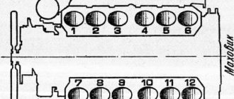
Rice. 13. Diagram of the position of the ball tips of levers A, B and C: 1 - IV - modes; 1st - 4th shift gears: A - lever for switching on the transfer shaft modes; B — lever for turning on the load shaft modes; C - gear shift lever
In Fig. 13 shows the position of the ball ends of the levers when changing gears. Lever A for switching on the transfer shaft modes has two positions: extreme forward and extreme rear; lever B for switching on the load shaft modes - four positions: neutral, reverse position and two forward positions; gearshift lever C - five positions: neutral and four positions corresponding to the engaged clutches of the transmission drive shaft.
Power plant K-700, K-701
The engine power on the K-700 tractor reaches 220 horsepower. The first versions of this technique became available in the early 1960s. Excellent traction qualities of the tractor are provided by enlarged radial tires. The control drives and hydraulic system are designed for heavy loads.
Since the mid-1970s. The following versions of the Kirovets appeared: K-700A, K-701. They are equipped with the following types of engines: YaMZ 238, 240. The fuel system available on the tractor includes fine and coarse filters. The engine does not lose its performance properties when the equipment is operated in difficult conditions.
The installed four-stroke 8-cylinder engine YaMZ-238NM is fixed on the front semi-frame. The K-700 tractor is capable of reaching speeds of up to 33 km/h. The weight of different modifications of this version of the tractor varies. In particular, the mass of the vehicle is affected by the mass of the engine.
The K-701 tractor with a YaMZ-240BM2 engine produces 300 horsepower and is an excellent alternative to the powerful K-700. This technique remained in demand in agriculture for a long time. The power plant communicates with the transmission. The transmission includes a cardan gearbox, axles, and a clutch. These spare parts are reliable.
Drive axle differential K-700 and K-701
The differential is made in the form of a double-sided gear freewheel. When driving straight and when turning on slippery ground, it blocks the axle shafts and both wheels rotate at the same frequency. When turning on hard ground, it automatically disengages the outer wheel and transfers traction force only to the inner wheel.
Differential diagram of the drive axle K-700 and K-701
Let us present a diagram of the drive axle differential and give its description.
Differential of the drive axle of the K-701 K-700 tractors: 1 - axle shaft; 2 - bowl; 3, 10 and 11—hubs; 4 — spring cup; 5 and 9 — driven coupling halves; 6 - drive coupling; 7 - key; 8 and 17 — springs; 12 — internal coupling half; 13 and 16 — split rings; 14 — retaining ring; 15 — drive coupling ring; 18 — bushing; B - projections of the driven coupling halves; P and N - power cams; T - trapezoidal teeth.
The differential housing is assembled from a hub 10, a bowl 2 and a drive coupling 6. On both end surfaces of the coupling 6 there are rectangular power cams P. The same cams H are located at the ends of the two driven coupling halves 5 and 9. These coupling halves are connected by toothed rims to hubs 3 and 11 drive axle axle shafts. The gaps between the power cams are much wider than the cams themselves.
Springs 8 and 17 press the driven coupling halves 5 and 9 to the drive coupling. In this position, the differential housing, rotating with the driven gear, transmits torque through the power cams to both axle shafts.
When turning, the right and left wheels of the tractor should rotate at different speeds. This is achieved automatically using a special device located in the differential housing. It consists of parts mounted in coupling 6 and coupling halves 5 and 9.
In the hole of the coupling 6, a ring 15 with trapezoidal T teeth at both ends is secured with a spring lock ring 14 and a key 7. The internal coupling halves 12, attached to the floor couplings 5 and 9, are fitted with split rings 13 and 16 with the same trapezoidal teeth. Key 7 fits into the cutouts of these rings.
Transmission system features
Using the gearbox on the tractor, the driver can change the speed of the vehicle both forward and backward. The peculiarity of the gearbox on the tractor is that there is no clutch. The gearbox itself is mechanical, 16 speed (forward), 8 speed reverse. In this case, there is the possibility of hydraulic control. The gears present have straight teeth, this is well reflected in the diagram of this working device. Gear couplings are installed on a shaft with gears. They affect gear changes.
Changing speed modes on this equipment occurs without delay. The gear shift mechanism performs the function of controlling the flow of incoming oil. Due to this, the fuel is directed to the spool. The gear shift mechanism housing is cast from cast iron. There are special channels here that are necessary for the direct distribution of circulating fuel flows. An auxiliary element such as the drive shaft is responsible for changing gears on the tractor.
The crankcase includes the pedal and control levers. The gearbox has several shafts. The input shaft is driven by a metal flat disk. The intermediate and load shafts (refer to the lower part of the crankcase) are distinguished by their operating efficiency. It should be noted that the load shaft is mounted on bearings. The existing driven drums for 1st and 4th gears are equipped with special synchronizer brakes.
The fork for controlling the cargo shaft clutches is fixed on the reverse clutch. It provides quick engagement and disengagement of reverse gear.
Thus, the operation of the K-700 tractor helps to increase the productivity of agricultural work. The tractor clearance is 440 mm. This circumstance ensured good maneuverability of this technique. It should be noted that gear shifting is carried out without loss of operating power.
Possible faults
The design of the product is simple and reliable, but in some cases the element may fail for various reasons. This is due to the high degree of wear of its individual components, which will need to be replaced to restore it to working condition.
If you study the catalog of spare parts for the K 700 gearbox, you can conclude that the maintenance and repair of this tractor does not require significant financial investments, since spare parts, for example, the gearbox seal, are available at affordable prices. The most common problems with the gearbox of this model seem to be:
- difficult gear switching;
- reducing the speed of movement at any stage;
- sudden shutdown of transmission;
- jerking when starting to move, noise during operation;
Gearbox diagram
Owners of this type of equipment often have to deal with leaks from the axles of the unit, which requires immediate intervention and elimination. If such problems are detected, it is recommended to immediately begin to eliminate them.
Troubleshooting methods
In cases where gear shifting is significantly difficult, you will need to inspect the clutches and synchronizer for wear; if problems are identified, such elements must be replaced.
If the tractor slows down in one gear, it is most likely due to an oil leak or lack of oil in the crankcase. The oil level will need to be brought back to normal by eliminating leaks, but if the cause of the problem is wear on the friction discs, they will have to be replaced.
Noise during operation can be caused by a wide range of factors:
- gear wear;
- bearing failure;
- lack of oil in the crankcase.
Disabling the transmission can be caused by various reasons, but most often it is caused by the breakdown of couplings, shafts, and rod clamps. A less serious problem is jerking when the tractor starts to move, since it is caused by a clogged oil intake screen, which must be cleaned to restore operation.
Basic gearbox faults
Malfunctions and breakdowns in the gearbox in most cases arise as a result of wear and tear of the components available here and individual spare parts. Signs of when a gearbox repair on a K 700 is needed:
- difficulty changing gears;
- spontaneous gear shifting;
- oil leak;
- jerks;
- knocks, noises from the side of the box.
In case of any of these manifestations, the owner of the Kirovets must conduct a general diagnosis of the transmission.
Difficulty shifting gears may be the reason why the synchronizer brakes have become unusable. The cause of jerking may be due to loose fastenings. Also, adjusting the gearbox control drive can resolve the breakdown.
Repair of the K 701 tractor gearbox is necessary if increased heating of the installed gearbox is observed. As a rule, a low level of lubrication is noted in the gearbox. Fluid leakage from the drive axles occurs due to an increased oil level. Also, this may be the result of contamination of the breather. A consequence of the fact that the owner of the car has encountered a fuel leak may be worn out oil seals. Taking this into account, the tractor driver must monitor the oil level.
If insufficient pressure occurs in the hydraulic system, the gear coupling, roller, and bearing must be checked. It is worth inspecting the condition of the oil pump. If the pump has lost its performance, this element must be replaced with an option that will be suitable in its characteristics to the Kirovets working system.
Spontaneous gear shifting is another problem that can be eliminated by replacing worn parts or by adjusting the drive.
Driving the K 700 and other modifications will become more difficult if the gearbox pressure has dropped. There are several reasons for this, ranging from a clogged filter to a breakdown of the gear shift mechanism.
Preventive measures
Necessary preventive measures:
Gearbox part of the K-700 gearbox
- change the oil on time;
- monitor the pressure in the gearbox and prevent a decrease in performance when idling;
- regularly clean the oil passages;
- do not use worn or deformed parts, replace them;
- use original spare parts for the K-700 tractor;
- Wash the filters of the hydraulic power transmission control system.
It is important to remember that the K-700 gearbox is a complex system, and any unqualified intervention can lead to complete failure of the entire unit. The service life of the tractor gearbox is influenced by the type of oil used - it is necessary to choose the appropriate brands. If it is better to entrust complete repairs to professionals, then you can fill and change lubricants in the box yourself.
Related video: K-700 gearbox after repair
Publications on the topic
Features of the MTZ-82 gear shift scheme
Features of the YaMZ-236 gearbox design
What is the best oil to use for a chainsaw chain?
The need to eliminate any breakdowns that have occurred
The gearbox on the tractor ensures efficient starting and stopping of the machine. That is why it is necessary to take proper care of it. Ignoring any malfunctions with the transmission system can lead to spontaneous movement of special equipment, creating an emergency situation. Taking this into account, Kirovets must be periodically subjected to full diagnostics. This procedure includes checking the tractor components. First of all, these are mechanisms related to the engine and transmission system.
The duration of operation of the transmission system is influenced by what kind of fuel is added to the high-speed box. For the K 700 (701) gearbox, you should choose oils that retain their performance characteristics for a long time. It is allowed to fill the main and final drives with Nigrol.
You can carry out a fuel change in Kirovets either independently or entrust this procedure to mechanics who have experience in performing this work. Upon completion of the box repair, professional service centers must issue a guarantee for the work done.
For preventive purposes, it is necessary to clean the oil-conducting channels of the crosspiece. All worn or deformed components related to the gearbox must be replaced. It is better to give preference to original spare parts. This will guarantee that they will not fail prematurely. As a rule, the need to disassemble the gearbox arises as a result of prolonged use of the tractor.
When installing new spare parts into the system, certain rules must be followed. In particular, when it is necessary to install a drive shaft into the crankcase, there is a possibility that the bushing will be damaged. That is why it is advisable to entrust the work of replacing individual mechanisms to experienced craftsmen. To repair an engine or transmission, a special stand is required. The device removed from the tractor and fixed on the stand makes it possible to simplify the process of carrying out restoration work.
Thus, the gearbox installed on the tractor ensures efficient movement of the vehicle regardless of the choice of speed mode. The box has several drive stages. When repairing a gearbox, it requires disassembly, washing of its component parts, troubleshooting, and reassembly.