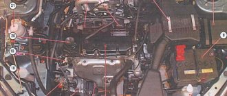
The relays and fuses of the UAZ Hunter are significantly borrowed from its predecessor - a carburetor classic SUV. Due to the update of the configuration and power plant, the modern injection Hunter received additional inserts, which greatly complicated the circuit compared to the outdated modification. Separately, the 514 diesel engine should be highlighted. A fundamentally different system is used here. Added new wiring circuit fuses. Fundamentally, the inserts are divided into two modules – interior and engine compartment. They differ in purpose and installed elements.
Prevention measures
What preventative measures will help protect your car’s electrical network from malfunctions:
- When the engine is off, limit the use of electrical equipment, as the battery will drain faster;
- From time to time, diagnose the performance of the battery and check its charge;
- ensure reliable insulation of the wiring;
- never use homemade fuses.
The main command vehicle of the armed forces - this is how the UAZ 469 SUV can be described. And indeed, having replaced the GAZ-69 in 1972, it secured this honorable duty for many years, proving the correctness of the design and main components with its endurance and reliability.
Historical reference
Traditionally, the UAZ 469 was produced in two versions:
- Cargo-passenger version - 7 seats and 100 kg of luggage;
- Commander version - 2 seats for passengers and 600 kg of luggage.
Industry standard 1945
According to the old vehicle classification system, in force since 1945, the UAZ 469 was produced under this name, using an alphanumeric name:
- The letter abbreviation UAZ stood for Ulyanovsk Automobile Plant;
- 469 is a serial factory index assigned by the enterprise itself to its models and developments.
1966 Industry Standard
Although at the time of the release of the UAZ 469 (1972) a new industry classification system was adopted (industry standard OH 025270-66), the car plant continued to use the name according to the old standard.
However, in 1985, the automaker was forced to change its name in accordance with current requirements:
- the car was assigned a four-digit number - 3151;
- According to the new system, the car can be called in the documentation as UAZ 3151.
The car plant named all further modifications and new models in accordance with current standards. In particular, the UAZ Patriot, which appeared in 2005, according to the industry classification, received the “correct” designation - UAZ-3163. For greater identification, the factory instructions contained both names.
Electrical equipment
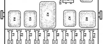
Each node is reliably protected from unexpected increases in current by special fuse links (fuses). They are assembled in a single mounting block, consisting of two lines, each of which contains 13 connectors with fuse links.
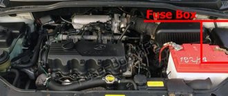
The compact unit is installed inside the car on the left side of the steering column. To make it convenient to inspect the elements of the block, a special backlight lamp with a built-in switch is fixed just above it.
In the engine compartment of the UAZ Hunter, another block is mounted, with strip-type fuses.
Each insert is responsible for a specific direction:
- starting switch;
- lighting fixtures outside the car;
- fuel filter heating;
- spark plug operation.
The purpose of the fuse links of the first and second blocks is to protect the electrical circuits of the equipment from overload and short circuit. Fuse housings come in different colors and are marked with the rated current.
The fuse links of the mounting block are installed in the following order.
| No. | What is he responsible for? | Note |
| F1 | Upper bar | Reserve |
| F2 | Side lighting | Right side of the body |
| F3 | Low beam | |
| F4 | Long range lighting | |
| F5 | Fog lights | |
| F6 | Lamp for illuminating the installation site of the mounting block | |
| F7 | Tail light brake lights | |
| F8 | Alarm | |
| F9 | Klaxon (beep) | |
| F10 | Rear license plate lamps and instrument lighting on the control panel | |
| F11 | Responsible for the cigarette lighter | |
| F12 | Rear fog lamp (if equipped) | |
| F13 | Reserve | |
| F14 | Bottom bar | |
| F15 | Side lighting | Left side of the body |
| F16 | Low beam | |
| F17 | Long range lighting | |
| F18 | Fog lights | |
| F19 | Reverse (white light) | |
| F20 | Direction indicators (right and left) | |
| F21 | Heater operation | |
| F22 | Windshield wiper motor and washers | |
| F23 | Interior lighting of the car and connecting the engine compartment lamp | |
| F24 | Reserve | |
| F25 | Operation of devices and alarms (sensors) | |
| F26 | Reserve |
Replacing a damaged electrical fuse
Before replacement, it is necessary to determine the reason why the protection tripped. If there is a short circuit in the circuit, the fault must be eliminated. If there is a short circuit, the procedure for replacing the electrical fuse with a new one is impractical. The product will burn out after being connected to a short circuit.
To replace you need:
- Find the electrical fuse box on the left side of the driver's wheel;
- Remove the protective cover with the lock installed on it;
- Turn on the lamp installed at the top of the product;
- Using the electrical diagram, determine which electrical fuse needs to be replaced;
- Remove the faulty product from the seat;
- Select a new product with identical face value;
- Install a new product into the cell;
- Check the functionality of the power supply circuit;
- Place the cover in place.
To replace the power fuse:
- Open the engine compartment of the car;
- Find the power products block on the panel of the power unit compartment;
- Remove the protective cover;
- Using the diagram, determine which element has failed (this can be done visually after opening the lid; parts of the burnt plate will be separated);
- Unscrew the nuts securing the plate;
- Dismantle the damaged product;
- On the inside of the cover, find a plate corresponding to the current strength of the dismantled part (the rating is applied to the plate by imprinting);
- Install the part onto the fastening studs;
- Secure the plate with nuts until it stops.
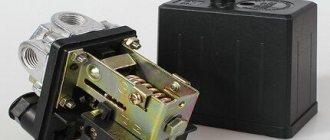
Where is the relay located in a UAZ Bukhanka car?
The all-wheel drive vehicle UAZ-452 (“loaf”) appeared in the 60s of the last century, and is still popular. But UAZ often breaks down, and in order to eliminate the malfunction, you need to know the location of its main relays.
Where is the fuel pump relay located?
The fuel pump relay is a device that supplies or cuts power to the fuel pump. It controls the fuel pump and performs a number of additional functions depending on the make of the car.
Typically, in “loaves” the fuel pump relay is installed in the area of the injection control unit, under the hood, behind the battery. Sometimes it can be found under the dashboard near the fuses.
Where is the charging relay located?
The charging relay consists of a reverse current relay, a regulator and a limiter. The reverse current relay turns the generator on when its voltage increases, and turns it off when the battery voltage increases.
The regulator controls and limits the current within 13.8 - 14.8 V, and regulates the charging current. The limiter protects the generator from overloads, working on a similar principle to the voltage regulator - it includes additional resistance in the winding circuit as the current increases.
The charging relay works in conjunction with the alternator under the engine hood on the right side.
Where is the starter relay located?
In UAZ there are two types of starters - 42.3708 and 4211.3708–01. They themselves are installed on the left side of the engine (in the direction of travel of the car).
The starters are equipped with an electromagnetic traction relay and a lever drive with a roller freewheel clutch. The blocking relay is located in the medical compartment and serves to prevent the starter from turning on when the power source is connected.
The wire from the relay goes to the central contact of the variator (with three coils) or to the coil connection contact (with two coils). This helps to strengthen the spark during engine starting.
Where is the turn signal relay located?
In UAZ vehicles, the turn signal circuit includes a steering switch, a turn relay, an hazard warning light and six bulbs.
This system is protected from overloads by several fuses:
- F8 – 10 A (for alarm);
- F20 – 7.5 A (for direction indicators).
Turn signals without a relay will not blink, so its malfunction is easy to determine.
It is located in the mounting block, on the left side, at the driver’s feet. In ambulances and utility vehicles such as UAZ, the turn relay is installed on the partition, behind the driver's seat.
If the relay malfunctions, it must be removed, and the use of metal objects is not allowed.
Plate elements
The designers of the Ulyanovsk Automobile Plant equipped the model with a power fuse block. It is located in the engine compartment. Depending on the modification, the power element blocks differ:
- Models 315143 and 315148 have a four-element design;
- 315196 and other modifications are equipped with a device with two fusible plates.
Fusible plates designed for a certain current strength are used as power elements. If the permissible current is exceeded, the plate burns out. To ensure good contact, the plates are clamped with nuts. You can also read about the 417 UAZ engine.
Electrical wiring components for UAZ 469, UAZ 390945 and other models
The electrical circuit of the UAZ 3151 4 includes 69 positions; it is possible to additionally connect special fog lights, but the installation of a switch type 343.01.03 is required. It will be mounted directly on the dashboard in a convenient location. The general wiring diagram of a machine includes an extensive list of different devices.
This is a front light, headlights that are easy to replace if necessary. An audio signal is also connected to the general system. Further, the UAZ wiring diagram includes a special fuse and additional resistance. The circuit has a connection to the side direction indicators, and a switch for the heater is located right there.
The wiring supplies the generator, there are connection points for the light that illuminates the engine compartment, and outputs for the heater fan motor. Modern UAZ electrical wiring includes spark plugs powered by it. A relay is installed for indicators; it is used to ensure the operation of emergency and turn signals.
The electrical circuit has outputs to a coil, a starter relay, there is a special sensor-distributor, and a switch. In one area there are the following points: turn off the masses, hazard warning lights, battery, electric washer. There is a separate connection for the fuse box and the following sensors:
- emergency pressure for oil;
- fuel readings;
- for oil pressure indicator;
- overheating of used coolers;
- temperatures of the coolers used;
- determining the brake fluid level.
Main relay and UAZ Hunter electric fuel pump relay, ECU fuses
There are a lot of different relays in the UAZ Hunter, most of them controlling the headlights, turns and windshield wipers are located in a visible place on the left side of the front panel on the driver's side. However, there are two relays located in the engine compartment, about which only a few lines are written in the official operating manual, this is the main relay and the electric fuel pump relay of the engine management system.
Meanwhile, the serviceability and performance of these two power relays directly determines whether you can even start the car’s engine or not, since through the relay, the main ECU supplies power to all actuating electric mechanisms and sensors of the system, which have a rated supply voltage of 12 Volts, and the electric fuel pump relay supplies voltage to the electric fuel pump of the fuel supply system and to the heating circuit of the oxygen sensor.
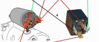
The main relay and the electric fuel pump relay are installed in the engine compartment on the front panel above the engine, to the right of the vacuum brake booster, when looking along the vehicle. Both relays are exactly the same, with the same catalog number 90.3747-10, and have no visible external differences.
Relays are four-contact, electromagnetic type with normally open contacts, designed to control power circuits up to 30A. You can distinguish them externally by the following feature: thicker wires with a larger cross-section are suitable for the main ECU relay block.
Structurally, the power relay 90.3747-10 consists of an insulated base with four pressed-in pins and an electromagnet coil mounted on it with an armature and a movable spring-loaded rocker contact, and a plastic housing pressed along the contour of the base. The relay is connected to the wiring harness using four-pin sockets.
— Power supply range: 8-16 Volts — Rated voltage: 12 Volts — Control current: no more than 0.2 Ampere — Operating voltage: not less than 8.0 Volts — Release voltage: 1.5-5.0 Volts — Maximum current in the power circuit: 30 Amperes— Active winding resistance: 80+-10 Ohm
Fuses for power circuits of the engine electronic control unit (ECU).
Next to the main relay and the electric fuel pump relay, two blade fuses are attached to additional blocks. 10 ampere, red - to protect the ECU power circuit coming from the ignition switch, and 20 ampere, yellow - to protect the ECU power circuit coming from the battery, the electric fuel pump power circuit and the oxygen sensor heating circuit.
The need for protection and periodic maintenance of the relay.
The location of the main relay and the electric fuel pump relay in the engine compartment is very contradictory; on the one hand, there is good access to them, and on the other, they are constantly exposed to condensation or rainwater that penetrates through the gap between the body and the rear of the hood. The relays are practically recessed in thick sound insulation and are screwed directly through it with their brackets to the panel.
Water and condensation flowing down the sound insulation end up on the pads, relay and fuse contacts, which begin to quickly corrode and, accordingly, do not provide good contact or even fail. To protect and reduce the negative impact on relays and fuses, it is advisable to somehow move them away from the sound insulation, for example, by taking longer screws and re-fastening them through thick rubber washers, or even by making some kind of protective casing for them.
In any case, these relays, along with the fuses, must be removed at least once a year and their contacts must be cleaned of any corrosion that has arisen; this will directly affect the operation of the engine, you will feel it immediately, especially when it is idling.
Diagnosis of faults associated with the main relay and the UAZ Hunter electric fuel pump relay.
Error codes for the engine management system with the Mikas 7.2 ECU associated with the main relay and the electric fuel pump relay, other external signs of malfunction of them or their electrical circuits, troubleshooting methods, as well as analogues and options for replacing the main ECU relay and the UAZ Hunter electric fuel pump relay are discussed in detail in the following material.
What components and assemblies are protected by fuses?
The mounting fuse block on the UAZ Hunter provides reliable protection for the following components:
- Side lights and main vehicle lighting.
- Operation of turn signals.
- Cigarette lighter.
- Sound accompaniment (horn).
- Windshield wiper operation.
- Car interior lighting.
- Stop lights.
- Heating system of the car.
- Audio system and radio equipment.
- Heating system pump.
- Illumination and operation of instruments on the panel.
- Backup equipment.
The UAZ Hunter is equipped with fuses for various components located on a block in the vehicle interior. But there are two more relays that are located under the hood of the car:
The performance of the power unit depends on the correct operation of these relays, since 12V voltage is distributed through the main power supply to all electrical components of the car and sensors, and the fuel pump relay supplies energy to the fuel pump and oxygen sensor.
In appearance, both relays are completely identical, even the catalog number is the same. They are installed on the right side of the brake booster on the shield above the car engine.
You can distinguish relays from each other by the wires that connect to them. The main ECU relay is approached by wires with a cross-section larger than that of the electric fuel pump. Two fuse links are installed near them. They are shaped like a knife. One, red, ensures the operation of the ECU electrical circuit from the ignition system, the other, yellow, protects the circuits from the battery, fuel pump and oxygen sensor.
The installation location of the two relays was chosen well in terms of maintenance, but it is in this place that they are exposed to running water after rain and condensation. Therefore, they must be removed periodically, at least once a year, and the contacts must be cleaned from corrosion.
UAZ Hunter cars with diesel engines are additionally equipped with a relay and fuse box, as shown in the diagram.
Proper operation of fuses is an important component of the entire vehicle system. Failure or incorrect operation of at least one of them allows you to timely identify the impending danger and eliminate the malfunction.
This helps to extend the life of individual components and the vehicle as a whole, and also increases the safety of the driver, passengers inside the car and other road users.
Wiring diagram for injection UAZ loaf
One of the most common problems with domestic cars is the breakdown of any electrical devices; an electrical diagram will help you figure this out. The only solution to this problem will be to check the condition of the fuses. The topic of today's article will be the electrical circuit of a UAZ Bukhanka car on an injector-type engine.
UAZ Bukhanka
So, this article provides answers to these fairly common questions:
- What is the electrical circuit on a UAZ Bukhanka car with an injector type engine?
- How does the electrical circuit of the UAZ Bukhanka car work?
- Where are the fuses located on a UAZ Bukhanka car with an injector type engine?
- Repair of the mounting block.
Starter UAZ Electrical equipment UAZ
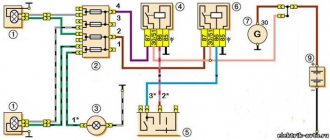
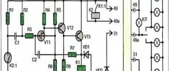
Starter 42.3708 (Fig. 261) or 4211.3708-01 with an electromagnetic traction relay and a lever drive with a roller freewheel clutch is installed on the left side of the engine (along the direction of the vehicle). The starter connection diagram is shown in Fig. 262.
Rice. 261. Starter 42.3708:
1-cover on the drive side; 2-lead ring; 3-thrust ring; 4-lock ring; 5-wheel drive; 6-anchor; 7-body; 8-brush; 9-traverse; 10-thrust washer; 11-adjusting washer; 12-lock washer; 13-cover from the collector side; 14-pin bolt; 15-pin plate; 16-relay cover; 17-return spring; 18-rod; 19-relay anchor; 20-compensating spring; 21-buffer spring; 22-gear; 23-screw M5x14; 24-nut tie rod; 25-screw M6x16; 26-nut M8; 27-relay coil input; 28-screw M6x30; 29-lever; 30-nut M8; 31-axis lever
Rice. 262. Starter connection diagram:
1-mass switch; 2-rechargeable battery; 3-additional starter relay; 4-ignition switch (lock); 5-voltmeter; 6-pin disk; 7-retractor winding; 8-holding winding; 9-traction starter relay; 10-starter
Periodically perform the following maintenance work on the starter:
- Check the condition of the clamps, making sure they are not dirty or loosened.
- Remove the protective casing and inspect the manifold, correct any faults if necessary.
- Open cover 13 (see Fig. 261) on the collector side, inspect and, if necessary, clean the contact surfaces, then blow with compressed air.
- If necessary, tighten the starter housing pinch bolts.
- Check the connection of the starter to the clutch housing.
- When operating the vehicle in difficult conditions, remove the starter to clean the drive and freewheel from dirt.
Every 32,000 km of the vehicle, perform the following maintenance work on the starter:
- Remove the starter from the engine.
- Check the condition of the commutator and brushes. Make sure that the brushes do not jam in the brush holders. If the brush height is less than 6 mm, replace them.
- Disassemble the starter. Replace worn parts.
- When assembling, lubricate the bearings and shaft journals with engine oil. Lightly lubricate the splined part of the shaft, drive offset bushings, fingers and the lever axis with Litol-24 grease.
UAZ starter: https://uaz.service-manual.company/elektrooborudovanie-uaz/starter-uaz/
Main faults of the UAZ-469 starter
What to do if the armature does not rotate when you turn on the starter.
| Probable cause of the malfunction | Remedy |
| Contact between brushes and commutator is broken | Remove the starter from the engine, disassemble it and eliminate the cause of the malfunction |
| There is no contact in the starter traction relay switch | Disconnect the wires from the starter, remove the switch cover with terminals. If the contacts are burnt, clean them. Rotate severely burnt contacts 180° around their axis |
| Broken connections inside the starter or in the traction relay | Repair the starter in a workshop |
| There is no reliable contact in the ignition switch at terminal “C” | Check the circuit using a test lamp connected to terminal C and ground. If there is no voltage at terminal “C” in the position corresponding to the starter turning on, replace the ignition switch |
| The winding is broken or the contacts in the additional relay are burnt | Check the circuit with a test lamp. The lamp connected to terminal “K” of the additional relay and ground should light up when the starter is turned on. If the lamp does not light, then disassemble the relay and clean the contacts |
| The armature is stuck in the sleeve of the electromagnet coil | Clean the armature, relay and bushing from dirt. If there is displacement of the traction relay relative to the starter lever, have it repaired in a workshop. |
What to do if, when the starter is turned on, the engine crankshaft does not rotate or rotates at a low speed.
| Probable cause of the malfunction | Remedy |
| Battery is discharged or faulty | Check the battery and replace if necessary |
| Short circuit of the armature or field coils or the armature touching the poles | Repair the short circuit or send the starter to a workshop for repair. |
| The engine crankshaft is difficult to turn | In winter, warm up the engine |
| The starter power supply circuit is broken due to loose wire ends | Inspect the entire starter power circuit, tighten all clamps |
| Severely worn bearings | Send the starter to a workshop for repair |
What to do if, when turned on, the starter shaft rotates at a high speed, but does not turn the engine crankshaft.
| Probable cause of the malfunction | Remedy |
| Broken flywheel teeth | Change the crown |
| Roller freewheel slips | Change the starter drive |
What should you do if, when you turn on the starter, you hear a repeated strong knock of the traction relay and the gear on the ring gear, but the engine crankshaft does not turn.
| Probable cause of the malfunction | Remedy |
| There is no reliable contact in the clamps, especially on the battery | Check and tighten clamp bolts |
| Battery is discharged or faulty | Check and charge the battery or replace it |
| The holding winding of the traction relay is faulty or its contact with ground is poor. | Replace the winding or ensure reliable winding contact |
UAZ Hunter UAZ 469. Fuses and relays
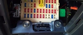
Location of the fuse box in the passenger compartment. . The unit is located under the instrument panel on the driver's side.
The relays are located under the instrument panel on the driver's side.
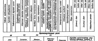
1 — relay for low beam headlights; 2 — relay for turning on the high beam headlights; 3 — relay for turning on fog lights; 4 — tailgate glass wiper relay; 5 — relay for turning on the rear fog lamp; 6 — windshield wiper relay; 7 - turn signal interrupter relay
The fuel injection system relay and fuse are located in the engine compartment.
Power fuses are located under the hood.
Power fuses protect the external lighting circuits and terminal 30 of the ignition switch.
Electrical diagrams of the fuse box UAZ Hunter, UAZ 469. Electrical equipment of cars modifications 315195-025, 315195-125
Electrical equipment of cars modifications 315195-023, 315195-123
1 — right front lamp; 2 — right headlight; 3 — left fog lamp; 4 — sound signal; 5 — right fog lamp; 6 — left headlight; 7 — left front lamp; 8 - generator; 9 — coolant temperature sensor; 10 — emergency oil pressure sensor; 11 — oil pressure sensor; 12 — emergency coolant temperature sensor; 13 — electric washer; 14 - switch for warning lamp for brake system malfunction; 15 — starter; 16 — battery; 17 — ground switch; 18, 19 — fuse block; 20 — starter relay; 21 — engine compartment lamp; 22 — power fuse block; 23 — fuse box lighting; 24 — side repeater; 25 — windshield wiper breaker; 26 — side repeater; 27 — fog lamp relay; 28 — brake light switch; 29 — heater electric motor; 30 — windshield wiper; 31 — heater resistance; 32, 33 — headlight switching relay; 34 — fog lamp relay; 35 — rear window washer time relay; 36 — instrument cluster; 37 — speedometer; 38 — block; 39 - engine fault warning light; 40 — control lamp for turning on the high beam headlights; 41 — indicator lamp for direction indicators; 42 — indicator lamp for turning on the parking brake; 43 - warning lamp for brake system malfunction; 44 — warning lamp for emergency oil pressure; 45 - warning lamp for emergency coolant temperature; 46 — battery discharge warning lamp; 47, 48 — indicator lamp for backup warning device; 49 — relay for direction indicators and hazard warning lights; 50 — parking brake warning lamp switch; 51 — heater mode switch; 52 — ignition switch (lock); 53 — ignition switch (lock) relay; 54 — light signaling switch; 55 — sound signal button; 56 — wiper switch; 57 — fuel level sensor switch; 58 — rear fog lamp switch; 59 — alarm switch; 60 — interior lamp; 61 — cigarette lighter; 62 — interior lamp switch; 63 — reverse light switch; 64 — fog lamp switch; 65 — external lighting switch; 66 — rheostat for instrument lighting; 67 — speed sensor; 68 — electric fuel pump with fuel level sensor; 69 — fuel level sensor; 70 — rear windshield wiper; 71 — rear window washer; 72, 78 — rear lamp; 73 — reversing lamp; 74, 76 — license plate light; 75 — additional brake signal lamp; 77 — rear fog lamp; 79 — air flow sensor; 80 — throttle position sensor; 81, 84 — temperature sensor; 82 — camshaft position sensor; 83, 85, 88, 92 — fuel injector; 86 — additional air regulator; 87 — knock sensor; 89, 90 — ignition coil; 91 — crankshaft position sensor; 93, 95 — automotive relay; 94 - fuse 10 A; 96 - fuse 20 A; 97 — diagnostic block; 98 — engine ECU; 99, 100, 101, 102 — spark plug; 103 — oxygen concentration sensor; 104 — adsorber purge valve
Additional block
The manufacturer equipped modifications with a diesel power unit with an additional unit. It contains fuses and relays. It is installed on the side wall of the engine compartment.
The fuse block of the UAZ Hunter 315195 diesel has the following fusible elements:
- F1 and F2 are fusible elements of the on-board network. They have a permissible load of 30 Amps;
- F3 – fusible element of the fuel heating relay. Nominal 25 Ampere;
- F4 – diagnostic fuse with a permissible load of 5 amperes;
- F5 – electric starter relay protection – 20 Amperes;
- F6 – protection of the sensor that controls air mass flow by the power plant – 10A;
- F7 – fusible element of the electronic control unit – 5 A;
- F8, F9, F10 – protection of main relays. the elements are rated 15, 10 and 25 Amps respectively.
Engine compartment
For many years, the main power unit of the UAZ 469 was the in-line 4-cylinder UMZ-451MI carburetor type. The engine capacity was 2445 cc. cm, power – 75 hp.
With this engine produced by the Ufa Motor Plant, the UAZ 469 lasted on the factory assembly line until 1985.
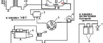
It was distinguished by a simple single-wire 12-volt ignition circuit, which consisted of (according to the numbering):
- rechargeable battery (AB);
- mechanical ground switch;
- electronic battery charge voltage regulator;
- alternator;
- ammeter on the instrument panel;
- ignition switch (switch);
- ignition breaker contact group;
- directly to the ignition distributor (distributor);
- capacitor built into the distributor;
- ebonite distributor cover with leads for high-voltage wires;
- ignition distributor slider;
- spark plugs;
- high voltage wires from the ignition coil;
- additional coil resistance;
- starter relay;
- directly to the high-voltage ignition coil;
- electric starter.
New modifications of the legendary SUV received more modern engines and a modified electrical circuit.
In particular, the UAZ Patriot wiring diagram includes:
- electronic fuel injection system;
- contactless ignition system;
- climate control system inside the car;
- alarm system, etc.
Blog about UAZ
The electrical equipment of UAZ Hunter cars models 315195-023, 315195-123, 315195-025, 315195-125, manufactured before 2010, is mainly made according to a single-wire circuit. The negative consumer outputs are connected to the car body, which acts as a second wire. The rated voltage in the on-board network is 12 Volts. The electrical diagram is presented below.
Electrical circuit diagrams for UAZ Hunter models 315195-023, 315195-123, 315195-025, 315195-125, manufactured before 2010.
The electrical circuits of the engine control system are made according to a multi-wire circuit and are connected to the vehicle ground only through the electronic control unit. To switch the main circuits of the car, a combined ignition switch is used, which includes a contact part and a mechanical anti-theft device with a lock.
The switches for the exterior lighting and fog lights, and the operating mode switch for the electric heater fan are located on the console under the instrument panel. The switches for the high beam headlights, turn indicators, windshield wiper and washer are combined into a block of steering column switches. High-power electrical consumers are switched on through separate electromagnetic relays.
Electrical diagram of UAZ Hunter models 315195-023, 315195-123 with a ZMZ-409 engine and an electronic fuel injection and ignition control system with a MIKAS-7.2 control unit.
What is included in the electrical circuit
The above is a form of electrical wiring diagram.
Regardless of which UAZ you use - old or new model - the main components of the electrical network are as follows:
- Dashboard. It displays the main sensors and indicators indicating that a particular device is turned on. Tidying allows the driver to know at what speed he is moving, how much fuel is left in the tank, what the crankshaft speed is and what the engine temperature is. In addition, there are many lights installed on the tidy that light up synchronously with the switching on of certain devices.
- Accumulator battery. The battery is an integral element of any car; it allows you to power the vehicle’s equipment when the engine is turned off, and also helps the ignition system in starting the power unit. If the battery is discharged, you will not be able to start the engine in the traditional way - you will either need to recharge it or try to start it with a pusher.
- A generating device, the failure of which will also make it impossible to start the engine. This unit provides voltage to all devices and devices used in the car while driving.
- Fuse block. This device contains all the safety devices designed to protect electrical circuits and devices from overvoltage. If there is a power surge in the network, then the main blow will be taken by the fuse (author - Ben & Ice Video Master channel).
Safety precautions when performing work
When replacing electrical fuses, it is necessary to use tweezers made of non-conducting materials. This will prevent voltage transfer from the circuit to the adjacent electrical fuse.
Before replacing, you must make sure that there is no short circuit in the circuit. A new electrical fuse is installed with the power circuit turned off. When installing, you must pay attention to the amperage indicated on the product. Installing a more powerful product can lead to overheating and fire of the insulating layer of the wiring. An element with a lower current rating will not withstand the load of the electrical circuit and will burn out.
Installing a homemade electrical fuse (bug) is strictly prohibited. The maximum load of such a device has not been determined. If a short circuit occurs, it may cause a fire.
From the above it follows that the fusible element block of the UAZ Hunter car is necessary to protect the electrical wiring from overloads and short circuits. The models are equipped with two blocks, the location of which is described above. Some car modifications are equipped with an additional unit.