With the release of more and more new technologies and the improvement of engines, many motorists forget about the oldies who won the hearts of millions. Thus, the old ZIL power units have long been outdated and are almost out of use. But, in certain regions of the CIS countries, these engines continue to be used, undergoing major repairs again and again.
Reasons for repairs
Before we begin to directly consider the issue of carrying out major repairs, it is worth considering for what reasons it is being carried out. So, why does the ZIL engine fail:
- Wear of main elements, such as the crankshaft or power unit cylinders. This is related to work and resource development.
- Burnout of the piston mechanism due to exposure to time, as well as the use of low-quality fuel.
- Mechanical damage to the cylinder head and block. Presence of cracks and wear on the seals.
The main reason is wear of all parts during operation or breakdowns.
Overhaul procedure
Overhauling a ZIL engine is quite difficult and is not always a cost-effective solution. But, since buying a new car or cylinder block will cost much more, as practice shows, they try to repair the ZIL engine.
So, as in any case, a major overhaul begins with dismantling the engine. Since there are several engine options, this is a purely individual process, moreover, the engine may not be located on a ZIL car, but, for example, on a LAWN. Therefore, we skip this procedure and immediately proceed to disassembling the power unit.
Disassembly
After the power unit is disassembled, you can begin the disassembly process. The first thing that needs to be removed is the carburetor. Since the fuel supply system was removed at the dismantling stage, only this element remained. To remove the carburetor, you need to unscrew the 4 fastening nuts and lift the part up. After this, you need to unscrew the studs from the intake manifold. If you cannot do this using standard methods, a stud and bolt puller will help.
The next step is dismantling the collectors. In this case, everything is simple. To dismantle the elements, you need to unscrew the fastening nuts and pull the collectors off their mounting locations. Next, it is necessary, as in the case of the carburetor, to unscrew the studs from the cylinder block.
After unscrewing the fastening nuts, remove the valve covers, of which the engine has two. Then, you need to move on to disassembling the auxiliary units. If the generator and starter were not removed during disassembly, then they must be dismantled after first removing the drive belt.
Next, you need to remove the fuel pump, centrifugal oil filter, drive belts and pulleys. If the engine oil has not been drained, it must be drained. To do this, unscrew the drain hole bolt. After draining the engine oil, unscrew the sump mount and remove the element.
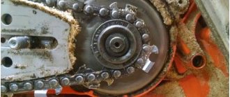
Next will be the dismantling of the main engine elements. We dismantle the water pump. By unscrewing the mount of the block heads, the elements are removed from the engine. Turn the motor over and unscrew the yoke mounting bolts. After the yokes are removed, it is necessary to unscrew the connecting rod journal mounting bolts. The crankshaft is now removed from the cylinder block.
It is worth noting that as the connecting rods are unscrewed, the pistons are removed along with the second part of the connecting rod and oil scraper rings. In this case, you need to be careful so that the heavy element does not fall on your feet, since the engine is upside down.
So, the main elements have been removed from the cylinder block, and repair and restoration operations can begin. So, all structural elements and engine parts are washed using hot kerosene.
Measurements and diagnostics of units
As practice shows, the cylinder block is already lined, and therefore boring occurs directly on the engine itself. If the block was under repair, then it may need to be sleeved. It is recommended to entrust this operation to professionals at a car engine repair service. Let's consider the dimensions of repairs and boring of a cylinder block using the example of the ZIL 130 engine:
| Repair | Size |
| Standard | 130.0 mm |
| 1 | 130.5 mm |
| 2 | 131.0 mm |
| 3 | 131.5 mm |
| 4 or more | Block sleeve (installation of sleeves of standard size 130.0 mm) |
As for the crankshaft, it also needs to be measured and checked for hardness. This is done for the purpose that on trucks the load is much higher, and therefore the main element can break under heavy load, and this will lead to damage to all internal elements, and the engine will have to be overhauled again.
As practice shows, a repaired crankshaft up to a size of 1.00 mm or more does not last long and tears under load. Let's consider the main dimension of the ZIL crankshaft liners:
| Type of repair | Size |
| 1 | 0.25 mm |
| 2 | 0.50 mm |
| 3 | 0.75 mm |
| 4 | 1.00 mm |
As practice shows, often crankshafts, especially those that have been repaired previously, are no longer suitable for boring due to loss of hardness. Therefore, engine owners have to look for a new one or a used one with minimal repairs.
Also, diagnostic operations include disassembling and determining the dimensions of parts of the cylinder head.
Block boring
Boring of the power unit is carried out on a special boring stand, where the cylinders or liners are adjusted to the size of the piston. It should be understood that the pistons must be adjusted according to weight so that there is no imbalance. This operation is done on a lathe, where the edge is removed from the product to remove excess grams.
After the block is bored, it is necessary to carry out honing. This operation involves polishing the cylinder walls to a mirror image. When the boring and honing has been completed, the planes of the block should be ground. This is done so that the plane of the cylinder block fits tightly to the head, and there are no leaks of liquids, and also the “coolant” does not accidentally get into the cylinders.
Cylinder head repair
Repair of the block head begins with disassembly. First the camshaft is removed. The next stage of disassembly is the removal of valves, seats and guide bushings. As for the latter, it is recommended to warm up the head so that when knocking out the bushings the seats are not damaged.
After complete disassembly, it is recommended to wash the part from metal shavings and clean it. This will help you find out if there are any cracks. If, however, depressurization is present, then the breakdown site must be welded. This operation is performed using argon welding. If there are many cracks or one but large one, it is recommended to replace the cylinder head housing.
When the cylinder head is disassembled, you can proceed directly to assembly. First of all, the guide bushings are turned on a lathe and adjusted to the dimensions of the valves. By the way, 11 mm repair exhaust valves are installed on ZIL engines. After the guide bushings are ready, they can be installed in the head body. After this, saddles are installed, which go through the rolling stage.
When everything is ready, the valve chamfer is adjusted on a special machine, and they are ready for installation. Also, it is worth pre-polishing the camshaft cams if it does not need to be changed.
Assembly
Now that everything is ready, you can begin the assembly process. The first step is to balance the crankshaft. It is necessary to perform the operation, since without it the engines and main structural elements will quickly wear out.
When the clutch is balanced, it is necessary to begin laying the crankshaft. It is placed in the cylinder block, and the main liners are installed, which are secured with yokes. The liner and main journal must be lubricated with engine oil. It is recommended to use motor fluid marked M-8.
When the crankshaft is laid, the operation of ligating the piston mechanism follows. This means that the piston and connecting rod are assembled, and then the connecting rod journal is attached to the crankshaft. The process is identical to attaching the yoke.
Now that the main elements have been assembled, you can begin installing additional components. A water and oil pump are installed on the car. After this, you can install the sump housing and the rear block cover.
The next stage of assembly is the installation of the cylinder heads. So, the studs that were removed during disassembly are screwed into the block. Block heads are installed on them. Then, you can mount the valve covers and install the manifolds.
We install additional components on the engine that were removed during the disassembly stage - the starter and generator. After this, you can install the pulleys and drive belts. To completely assemble the cooling system, you need to install the fan impeller. You can also install a carburetor.
The last step before running in is to fill the engine oil. So, depending on the modification, 10-14 liters of motor oil are poured into the ZIL engine. As practice shows, most owners are inclined to fill the engine with M-8 mineral oil. For diesel engine options, it is recommended to fill in liquid - M10-G2K or M10D.
Run-in
All engines, without exception, must be run-in after a major overhaul. So, if the repair is carried out in a car service center, then the engine is first run in on a special stand, and only then it starts and runs hot.
The running-in process is carried out on a special stand, where the crankshaft pulley is connected to an electric motor, which spins the crankshaft at different speeds. Then the valve mechanism is adjusted. After this, the power supply and exhaust gas systems are connected. The engine starts and runs hot. Next, the valves are adjusted again, and the motor can be installed on the car.
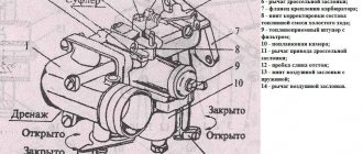
Design features of the carburetor
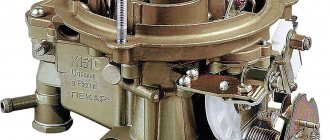
Before you begin setting up or adjusting a spare part, you should study the operating principle of the carburetors installed on ZIL 130 and 131. So, this is a two-chamber device with a falling flow of air mixture and double sawing of fuel. There are two carburetor chambers made in one block and operate in all engine modes in parallel.
The carburetor in ZIL 130 and 131, by the way, is designed in such a way that its adjustment is not a problem for the driver. If the device gets a little rough, you can set it up to work without having to remove and disassemble the device. However, before you begin tuning the carburetor, it is necessary to study its design even superficially. In particular, the screws with which the actual adjustment is made:
- Idle mixture quality adjustment screw.
- Throttle stop screw.
- Speed adjustment screw.
- Throttle locking screw.
- Jet holder.
Carburetor K 88
The carburetor itself is an order of magnitude more complex. However, this knowledge is sufficient for initial setup. Deeper ones are needed more for repairing the device, however, we will entrust this matter to qualified auto mechanics. If you have minimal plumbing skills, adjusting the idle speed as a solution to most problems with ZIL 130 and 131 carburetors will not be a problem for you.