Removal and disassembly of service brakes
Place the car on level ground, place a jack under the axle and lift it. Further:
- remove the wheel and then the hub cover;
- unscrew the fasteners holding the inflation hose;
- pull out the axle shaft;
- use pliers to bend the washer and unscrew the nut;
- remove the hub along with the brake drum and the bearing located inside;
- pull out the tension spring located on the brake pads and the brackets (these elements must be cleaned of dirt).
Then you will have to unscrew the pipelines along with the bolts to remove the working cylinder. Next, you need to dismantle the shield along with the felt gland. Remove the brake valve, air booster, compressor, which are easy to disassemble. There is a caveat: when disassembling the master cylinder, do not remove the plug. One more point: it is also better not to touch the compressor GC (except in case of emergency). The valve seats are pressed out after removing the valve guides using narrow nose pliers.
Inspection and checking of parts
After rinsing the brake linings in gasoline, they need to be dried and treated with fine-grained sandpaper (a wire brush will also work). These parts are replaced if the distance to the top of the rivets is less than 0.5 mm. To process the fist together with the block, you need to place a plate 0.98-1 mm thick between them. Drum grooving is required if the groove depth is more than 1 mm.
Working cylinders
They are subjected to honing if they have traces of rust and mechanical damage in the form of scratches. Inspect the pistons and cuffs: if there is severe wear, replace the parts. Cracks, through tears, and ruptures are not allowed on the rubber boot of the cylinder. To replace the caps you will need a special tool.
Master brake cylinder
Inspect its mirror: nicks and scratches are not allowed - the element will have to be replaced. If there are traces of rust, the cylinder can be honed. When installing later, use new cuffs. Take a look at the piston: you need to install a new one if the wear on the brake system parts is too great. The cuffs are changed if they show signs of swelling.
Compressor: inspection, disassembly
Inspect the housing: there should be no cracks or other mechanical defects. Take a close look at the mating surfaces, where nicks and warping are not allowed. The cavities must be clean inside (no deposits). All surfaces of the housing must be in the same plane: the difference is no more than 0.5 mm.
The next point is to inspect the sockets in which the crankshaft bearings are located. The maximum wear of the sockets cannot exceed a diameter of 72.05 mm. The maximum abrasion value of the intake valve is 0.8 mm, the permissible deviation from flatness is 0.01 mm. Inspect the plunger of the unloading device: there are no cracks or signs of heavy wear on it. The upper and lower connecting rod heads along the axes must be located parallel: per 10 cm of length the error cannot exceed 0.07 mm.
Brake drive
Clean, rinse in gasoline and inspect its elements. If there is damage (especially to pipelines), parts must be replaced. They need to be given special attention: this means mounting on bridges. Also, cracks and abrasions on the brake hoses are not allowed.
After completing all work, the brake system must be bled. Use only fluid recommended by the vehicle manufacturer. Mixing different formulations is not allowed.
Source
Removing and disassembling service brake parts
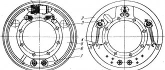
Remove the wheel and hub assembly with the brake drum, clean the brake mechanism from dirt and wash it.
Using the mounting spade as a lever, disconnect tension spring 2.
Remove the locking brackets 9, linings 8 and brake pads 6 from the axles 11 of the pads.
Disconnect brake fluid supply line 1 from the wheel cylinder, unscrew the bolts securing it to the shield and remove the cylinder assembly.
If necessary, unscrew the bolts and remove the brake shield.
If the pad linings or shoe assemblies cannot be replaced, then it is not recommended to unscrew the nuts 12 and turn the axles 11 in the shield bracket, which will allow the pads to take their previous position relative to the brake drum during assembly, and, therefore, will make it easier to adjust the gaps between the pad linings and the brake drum .
When disassembling the wheel cylinder, remove the springs of the caps 1 (Fig. 3), caps 2, assembled with pistons 4.
Air leakage from pipe connections
To eliminate this problem, you need to tighten the connecting washers. The tightening torque for pipelines of different diameters (Ø) is different.
- Ø 6 mm - max 18 Nm (1.8 kg/cm).
- Ø 10 mm - max 35 Nm (3.5 kg/cm).
- Ø 14 mm - max 45 Nm (4.5 kg/cm).
To prevent possible malfunctions of the connecting elements during tightening of the fittings, the torque should not exceed 50 Nm (5 kg/cm).
Advice! In order to evaluate the performance of the brake light, you need to press the pedal at the moment when there is pressurized air in the pneumatic unit.
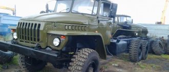
The design of the brake mechanism of the Ural 4320 and 5557 car
The working brake system of the Urals of the designated brands is designed to ensure gradual braking of the vehicle partially or to a complete stop, without depending on its speed before braking, terrain features (descent or ascent), specifics of the road surface and other factors.
The brake system of the Ural vehicle, assembly models 4320 and 5557, has a mixed type drive (pneumohydraulics), consisting of two circuits. At the same time, it is responsible for braking all six wheels, including the trailer, with the front and rear braking separately (on the axles).
The braking process is started by the brake pedal from the driver's cabin, which is connected by rods and levers to a brake valve, consisting of two sections.
Service brake device:
- A wheel cylinder consisting of two parts located in one housing.
- Brake shield.
- An eccentric for adjustment, which is carried out by turning the bolt using a key.
- Brake pads installed on supporting axles.
- Friction lining.
- Connecting elements - hoses, washers, holders, valves and others.
Service brake device Ural 4320
Brake adjustment process
The service brake adjustment algorithm includes the following sequence of actions:
Adjusting the service brake Ural 4320
- Using a wrench, turn the eccentrics of both brake pads until they stop.
- The left eccentric must be rotated against the clock hand, and the right one - along the clock.
- Loosen the eccentrics by turning them in the opposite direction by half the head of the axle bolt, which is comparable to turning the key 30 degrees.
- Carry out the above steps for all wheels.
- Check the correctness of the adjustment by assessing whether the brake drums heat up while the Urals are moving.
When adjusting the brakes, it is important to be careful not to change the factory location of their support axles in the brake pads. It is necessary to adjust the gaps only in parallel with changing the friction linings or the pads themselves. This is done by turning the support axes and inserting a special probe, the length of which is 200 mm, and the thickness depends on the position of the edge of the overlay and can have values of 0.2 and 0.35 mm. Oily linings must be thoroughly washed with gasoline.
How to bleed and adjust
To make the adjustment you must:
- Turn the eccentrics all the way, with the right part rotating clockwise and the left part counterclockwise. Adjustment of the gap using the pad axis is carried out only in case of wear of the braking surface.
- Loosen the position of the regulators by 30°.
- Check the temperature of the drums while moving. If overheating or insufficient deceleration occurs, readjust the components.
Before bleeding the brake lines, it is necessary to bring the air pressure in the receivers to normal. The surfaces of the cylinders and tanks should be thoroughly wiped from dirt.
To remove air locks from the main and wheel cylinders you need:
- Remove the protective cover installed on the bypass valve fitting. After this, the hose included in the factory tool kit is put on the tube.
- Prepare a clean glass or plastic container that can hold at least 0.3 liters of liquid. Fill the container 1/2 full with brake fluid and lower the free end of the hose into it.
- Unscrew the valve fitting 0.5-0.75 turns, then vigorously press the brake pedal several times, releasing smoothly.
- Manipulations continue until the release of gas bubbles from the tube stops. At the same time, clean liquid is added to the supply tank.
- Depress the brake pedal one last time and hold it in this position. Screw in the fitting and replace the cap.
- By analogy, bleed the wheel cylinders according to the scheme - middle (left), then rear left and right. Then the right middle wheel assembly, right and left front wheels are pumped.
- After removing air from all lines, adjust the fluid level in the supply tank and close the lid.
If fluid replacement is required, the cylinders are disassembled. A lubricant is applied to the working mirror to prevent corrosion.
Ural 5557
Brake system Ural 4320 diagram
How to pump up a steering wheel on a KamAZ
Gearbox Ural
Appearance and technical characteristics of the Ural-6370 truck tractor
Operation and repair manual for Ural-4320 and list of main faults
Master brake cylinder
This part is responsible for controlling the truck's working system. Increased reliability is ensured by two elements equipped with pneumatic amplifiers. The principle of operation of the Ural brake system is that the valve in the shut-off valve opens after pressing the pedal in the driver’s cabin. Air masses enter through special channels and holes into the piston of the reinforcing pneumatic unit.
Air is supplied to the second piston through radial sockets in the rod. Under pressure, all incoming masses act on the main cylinder, displacing fluid into the TM (brake line). When the car's brakes are released, air is released into the atmosphere through the stop valve. In this case, the pistons of the main center and the pneumatic amplifier return to their initial position. The front counterparts have indicators that notify you of possible problems with the car’s brakes.
Auxiliary brake
It is intended for use on large slopes. The control key is located on the cabin floor. If you activate it, the following chain of actions will start:
- Air under pressure is supplied to the brake cylinders of the URAL 5557, it affects the pistons and displaces them;
- in the exhaust gas pipelines, braking is carried out due to back pressure;
- at the same time, an impulse is sent to the truck brake.
When activating the additional brake, there are several things to consider:
- keep the engine crankshaft torque intensity to no more than 2100 min-1;
- You should not change gearbox speeds from higher to lower when the engine crankshaft torque intensity is close to 2100 min-1.
If necessary, you can reduce the intensity of the crankshaft torsion with the service brake, then activate the lower gear.
Now let's move on to calibration and maintenance.
This is interesting: Removing rust from a car body with your own hands
Peculiarities
The Ural brake system is equipped with drum mechanisms that are completely interchangeable. The pneumatic structure itself forms separate brake compartments for different parts of the machine (trailer, front, rear axle). If there is a malfunction in one segment, the remaining analogues in operation are responsible for braking.
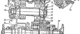
Below is a diagram of the master cylinder with explanations.
- Front pneumatic cylinder.
- Spacer element.
- Radial socket.
- Rear pneumatic cylinder.
- Stock.
- Compression screw.
- Nuts.
- Indicator.
- Main cylinder.
- Cork.
- Brake fluid reservoir.
Recommendations
The third circuit has a separate air tank and special valves to control the operation of the trailer wheels. It also includes connection heads that differ in configuration, depending on the drive they are intended for. The third circuit is responsible for stopping the trailer.
The compressor operates in cooperation with the regulator, which sends air flow to safety valves, which distribute the resulting mixture between all tanks in each circuit compartment. All chambers are equipped with pressure gauges that allow you to control the pressure indicator.
Brake valve drive
The brake valve drive device with a description of the elements is given below.
- Working pedal.
- Lever arm.
- Adjustment screw.
- Traction fork.
- Fixing nut.
- Drive traction.
- Brake valve lever.
- Bracket.
The safety valve must be adjusted if it does not maintain the pressure in the Ural brake system at the specified positions. Adjustment is carried out by rotating the corresponding screw. In this case, the pressure indicator increases, and after reaching the required parameter, the adjustment bolt is fixed with a nut. To avoid air leakage, the valve is removed, washed and cleaned (in kerosene). Workplaces are washed with soapy water and checked for wear and deformation.
Pneumohydraulic drive device
The Ural truck uses a mixed type drive, combining the functions of pneumatics and hydraulics - pneumohydraulic, which consists of two working circuits for the front and rear wheels, plus a third circuit responsible for connecting the trailer brakes (single-wire or double-wire drive).
Hydropneumatic brake drive
The two main circuits of the Ural braking system have the following components:
- Different air cylinders located parallel to each other.
- A brake valve, the upper section of which belongs to the first circuit, and the lower section to the second.
- Cylinder wheels and general brake booster (pneumatic).
- The second circuit additionally includes a brake force regulator.
Pneumatic brake booster for Ural car
- Separate air tank.
- Special valves designed to control trailer brakes (separately for single and dual wire actuators).
- Connection heads for each type of drive.
The pneumohydraulic drive of the Urals operates according to the following scheme:
Components of the brake system Ural 4320
- The compressor, through a pressure regulator, directs compressed air to the safety valves (single and triple).
- The valves distribute the resulting air between all cylinders in each independent circuit.
All circuits are additionally equipped with control outlet valves designed to measure air pressure by connecting a pressure gauge to them. The electrical signal sensor is driven (and some other devices) by air from the main air cylinders, from which the intake is carried out through a triple protection valve.
Malfunction indicator status assessment
On Ural-4320 and 5557 trucks, you can evaluate the activity of the alarm using the following method:
- evaluate the warning lamp;
- slightly unscrew the washers securing the wire to the control lamp deactivator;
- remove the activator from the pneumatic booster and tighten the wire fixing washers;
- turn off the equipment and short-circuit the activator body to the “ground” of the machine, press the button all the way;
- at this time, the equipment on the dashboard will light up, this indicates its proper operation;
- similar steps must be repeated with another activator.
If the indicator does not light up, the problem can be solved by simple replacement.
It is also important to know how to evaluate the performance of a truck's air drive.
Malfunctions of the Ural brake system
Among the malfunctions of this design, there are several malfunctions that occur most often in practice:
- weak pressure build-up in receivers due to breakage of main bodies or connections;
- filling the balloon circuits in insufficient volume, which provokes failure of the correction valves or excessive contamination of the associated components;
- low pressure in the air tanks on the trailer, which is most often caused by cracks in the parts;
- excessive pressure in the receivers due to a malfunction of the controller or pressure gauge;
- malfunction of the compression mechanism, which indicates serious wear of the compressor piston unit.
If critical malfunctions occur in this system, operating the vehicle is strictly prohibited. You should correct the problem on site or take the car to a repair bay using a rigid hitch type.
Repair work
When repairing parts of the Ural brake system, all devices and elements should be carefully removed, washed thoroughly and carefully checked for defects. The assembly is disassembled as follows:
- Using a jack, lift the serviced axle, remove the wheel and hub cover, then unscrew the tire inflation angle by dismantling the axle shaft using a puller.
- Bend down the lock washer and the outer lock, remove the lock and inner washer.
- The brake hub and drum are dismantled along with bearings, locking brackets, and pad springs. The bushing and pad pin are thoroughly cleaned.
- Unscrew the pipeline with bolts, remove the wheel-type cylinder, and remove the block support protrusions.
- Dismantle the brake shield and felt seal.
- When disassembling the main shopping center, do not unscrew the plug.
- It is recommended to disassemble the compressor main unit only if absolutely necessary. It is pressed out using a special puller.
- All oily and contaminated parts of the brake system of the Ural vehicle are washed in gasoline. If the distance from the surface of the linings to the rivet heads is less than 0.5 mm, the parts must be replaced with new modifications.
- The shoe elements of the hand brake are processed together with the expansion cam.
- Drums with ring grooves more than 2 millimeters deep must be machined.
- It would be a good idea to hone wheel cylinders that show signs of corrosion and abrasions. Items showing signs of excessive wear should be replaced.
Source
Adjustment and bleeding
Bleeding the Ural brake system with simultaneous adjustments is carried out as follows:
- Using a special wrench, turn the eccentrics of both brake pads until they stop.
- The left analog is rotated counterclockwise, the right element is rotated in the direction of travel.
- Then the eccentrics are loosened by turning the axial screw head 50% in the opposite direction.
- These steps must be repeated for all wheels.
- Check the correctness of the adjustment by assessing the heating of the drums while the vehicle is moving. When carrying out this procedure, the relationship between the factory location of the brake pads and the support axles should be observed. The gaps are adjusted by rotating the axes with the introduction of a special shunt device, which is 20 cm in length and thickness varies from 0.2 to 0.35 mm. Linings that are excessively oily are treated with gasoline.