The operation of electrical equipment in any modern car directly depends on the performance and integrity of the wiring. That is why every car owner must understand the electrical circuit of the car. In particular, we are talking about the legendary domestic UAZ cars. What the electrical circuit of the old-style UAZ-3303 is and what malfunctions are typical for it - we will talk about this below.
Nuances of electrical equipment
The electrical circuit of the on-board wiring for the UAZ 390945 includes the following systems:
- Ignition. This system consists of different elements - a distributor, a coil, spark plugs, high-voltage wires through which the charge is transmitted.
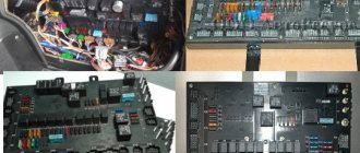
- Safety block. This unit is a set of safety devices designed to protect the electrical circuits of installed devices and electrical equipment.
- Glass washer. The washer system consists of windshield wiper blades, a trapezoid, an electric pump, an expansion tank, a gearbox and other components. The main purpose is to ensure high-quality cleaning of the windshield.
- Acoustics. Its presence is not relevant for all vehicles. The acoustic audio system includes a car radio, speakers, and an antenna adapter.
- Rear window heating system.
- Optics.
The operation of any circuit involves the use of a battery, as well as a generator device. The first is used to provide power to all equipment when the engine is turned off, and the second is used to power the battery, as well as power electrical devices when the engine is running (the author of the video is the Protect Your Interests channel).
Algorithm of operation of multifunction switches
The new scheme has caused many complaints from car owners with its “confusing” algorithm. However, a similar scheme is widely used on imported cars and is considered safer when driving.
Possible positions of the multifunctional steering column switch: A – headlights and direction indicators, B – windshield wiper and washer
The headlight and indicator light control lever indicated in the picture “A” has the following algorithm:
- Position I – low beam is turned on (if the central switch on the instrument panel is activated). In this case, the direction indicators are turned off;
- Position II (non-locking) – turning on left;
- Position III (fixed) – turning on the left turn;
- Position IV (non-locking) – turning on the right turn indicator;
- Position V (fixed) – enabling right turn;
- Position VI (lever toward you) – turning on the high beam (non-fixed position);
- Position VII (lever away from you) - turns on the high beam headlights, provided the central switch on the instrument panel is turned on (fixed position).
The control lever for windshield wipers and windshield washers, indicated in picture “B,” has the following positions:
- Floor. I – the cleaner and washer drives are de-energized;
- Floor. II (non-latching) – intermittent operation of the windshield wipers is activated;
- Floor. III (fixed) – similar to item 2;
- Floor. IV (fixed) – low speed of constant wiper mode;
- Floor. V (fixed) – high operating speed of the constant purifier mode;
- Floor. VI (lever toward you) – simultaneous short-term activation of the washer and windshield wiper (non-fixed position);
Position VI is required in emergency situations when an oncoming car splashes mud on the windshield. Simultaneous operation of the wipers and washer allows you to quickly restore visibility.
For reference: Provisions VII, VIII are not used on UAZ 3303 (created for reserve).
Possible wiring problems
What can lead to wiring problems:
- Broken wires or damaged insulation. In both cases, the only option is to replace the damaged section of the electrical circuit. An open circuit, as well as chafing of cables, can be caused by external factors, for example, if the wiring was laid where there are rubbing mechanisms. Before replacing the cable, it is necessary to eliminate the cause, otherwise the problem will soon occur again. Solving the problem of insulation chafing by wrapping several layers of insulating tape onto the cable is also impractical.
- Short circuit in the system. Such a malfunction can only be determined by diagnosing the electrical circuit using a tester - a multimeter. A short circuit can also be caused by chafing of power cables.
- Voltage surges. Such malfunctions may be caused by the use of too powerful energy consumers. Let's consider the simplest example: you installed a splitter into several sockets into the cigarette lighter socket. When the voltage consumers are turned on, a higher current charge is supplied to each socket of the cigarette lighter. The cigarette lighter socket is designed for a certain voltage, and if instead of one device two or three devices are powered, then, accordingly, the voltage passing through the socket will be several times higher. This contributes to the appearance of differences in the operation of the electrical system.
- Failure of the safety device. If the fuse blows, it is necessary to replace the failed element. But if burnout occurs too often, then you need to check the socket in which the part is installed. Perhaps the reason lies in voltage surges, so the fuse blows prematurely. The cause of the difference must be eliminated.
- Generator unit malfunction. Problems in its operation can be identified by reduced voltage in the on-board network, as well as dim headlights. Moreover, when the driver presses the gas pedal, the brightness of the optics increases noticeably. This usually indicates a failure of the voltage regulator or worn brushes.
- Oxidation of contacts at the ends of wires. Due to oxidation or damaged contacts, power to electrical equipment is disrupted because charge cannot flow to the device. The problem of contact oxidation may be a consequence of exposure to moisture on the wiring. This problem can be resolved by cleaning the contacts or replacing them. You can use fine-grit sandpaper for cleaning.
Continuity of components and assemblies
During the years of planned economic management, the price of cars was set centrally. And in order to keep costs in line, the automaker was forced to unify parts - use the same components and assemblies on different models at once.
For reference: all the world's leading automakers adhered to a similar scheme for unifying parts and assemblies. As a rule, a multi-purpose platform is first developed, and on its basis various car models with different designs and body shapes are produced.
In particular, the electronic components and all electrical wiring of the UAZ 3303 were used from the “452” model, a multi-purpose all-wheel drive vehicle that rolled off the factory assembly line in those years and was involved in cargo transportation throughout the country:
- Rechargeable battery brand 6ST-60EM;
- Alternating current generator G250-P2 with integrated voltage regulator PP132-A;
- Electric starter type ;42.3708;
- Ignition coil B116
- Distributor (ignition distributor 33.3706);
- Electronic (transistor) switch model 13.3734;
- Spark plugs type A11
For reference: Later modifications of the UAZ 3303 were equipped with new generation generators. This was due to the installation of the UMZ-4218 injection engine, which complies with EURO-2 environmental standards, as reported in the promotional video of those years.
Regular paddle switch
On the model of the first years of production, the instrument panel from the UAZ 3741 model was installed with virtually no changes. Therefore, the circuits for connecting electronic systems remained the same.
To control lighting devices and turns, a conventional type steering column switch was used, which had fixed positions:
- The direction indicator had 3 positions - turn left, right and off;
- The warning lamp (in diagram No. 6) informed the driver about his mode;
- The headlight switch (low and high) had two modes - only low and only high. The enabled mode was displayed using a warning lamp (in diagram No. 8) inside the speedometer.
For reference: with the ignition off, and also while driving, pulling the light switch towards you activated the high beam lamp switching circuit.
At the same time, the windshield wiper and washer controls (no. 23 in the instrument panel diagram) were located under the hazard warning switch button and had the following algorithm:
- The purifier was activated by rotating the handle;
- Pressing the handle (meaning recessing the rod in the axial direction) activated the washer.
Multifunction steering column switch
The modification of the car in 1993 received the index 3303-6. Among the changes made to the design of the car with an extended platform, special mention should be made of the multifunctional steering column switch, which significantly changed the interior wiring.
Its appearance is due to the new instrument panel, which the “three hundred and third” borrowed from the new UAZ 39094 model.
As a matter of fact, the algorithm for controlling the actuators has also changed:
- Control systems for wipers and windshield washers;
- Direction indicator control systems;
- Headlight control systems.
The features of the new switches were:
- Combination of the direction indicator control lever and headlight control lever;
- Removal of wipers and windshield washers from the instrument panel to the control lever;
- Addition of previously unused non-locking modes for levers.
How to determine the malfunction?
If there are problems with the electrical wiring, this can be determined by the following symptoms:
- The generator unit has stopped producing charging current. That is, the electrical equipment has either stopped being powered, or the current in the network is too low. Such a malfunction may be accompanied by noise during the operation of bearing devices.
- There are malfunctions in the operation of the starter mechanism. Now the device cannot crank the engine crankshaft, the rotor assembly can rotate, but the crankshaft does not turn. When you try to start the power unit, relay clicks may be heard. Also, the inoperability of the starter may manifest itself in the fact that the car engine starts, but after that the starter unit does not turn off.
- Another symptom of a wiring malfunction is the rapid discharge of the car battery. If the battery is relatively new and has not yet exhausted its service life, then its rapid discharge should alert the car owner. If after the next charge the battery still quickly discharges, you need to look for the reason. A malfunction in the operation of the battery can be indicated by a decrease in the volume of working fluid in the jars and an increase in its density during charging.
Wiring UAZ 3303: operating features
A two-seater off-road truck appeared on the assembly line of the Ulyanovsk Automobile Plant in 1985. The car received the index 3303, and the power unit, chassis, suspension and wiring of the UAZ 3303, according to the accepted unification, were borrowed from its predecessor, the “452” model.
For reference: to transport various goods, the national economy required a small cargo vehicle with an open body that could be serviced with one’s own hands. To simplify, we used the platform and power unit of the “452” model, replacing the all-metal closed body with a cabin and a cargo platform with folding sides.
Electrical circuit elements
The electrical circuit of the domestic UAZ is simple, since it is of the single-wire type. The standard wiring diagram for a UAZ “loaf” with a carburetor has the following features:
- the car body serves as a mass,
- The electrical diagram of the UAZ loaf with a carburetor and the actuators are equipped with a negative terminal connected to the housing.
The second feature is considered by experts to be an imperfection of this scheme.
Wiring diagram for a loaf with an injection engine.
When repairing electrical wiring in such a car, it is difficult to find a ready-made connection diagram - the manufacturer did not include it in the operating instructions.
It is believed that the wiring diagram for electrical appliances in UAZ loaf cars with an injection engine almost completely corresponds to the diagram that is used in a car with a carburetor, but in reality they are different.
To solve car control problems related to wiring, 2 connection schemes are used - standard for a loaf with a carburetor engine and injection for GAZ - 69 “Kozel”.
Combining the information from these two diagrams allows you to repair or reinstall the wiring in the injection loaf.
Instead of a circuit diagram for an injection GAZ-69, a circuit diagram for an electronic engine control system can be used, so drivers are advised to carry it with them along with a wiring diagram for a loaf carburetor engine.
These sources allow you to manage the wiring of the injection loaf throughout the car, but for some electronic components, if they are not provided for in the standard wiring diagram.
In this case, it is worth contacting specialized forums - more experienced owners of loaves can not only suggest a solution to the problem that has arisen, but also share the circuit that is missing for this, if their car is the same model as the faulty one.
Features of the equipment in the diagram
The start of production of the UAZ automobile was complicated for the designers of the Ulyanovsk plant in the search for high-quality components. This problem especially applies to lighting and ignition systems, so the company’s engineers were forced to use non-standard solutions to establish mass production.
Therefore, the wiring diagram of a UAZ loaf with a carburetor includes an optics switch from an older GAZ-69 car.
Domestic cars from time to time puzzle users with problems with electrical equipment. If the electrical wiring of your UAZ is not functioning correctly, you will have to check not only it, but also the other elements of the circuit.
First of all, the functionality of the fuses located in the installation unit is checked. Then the integrity of the lamps is checked, and the tester rings the electrical part.
I have a 1989 car, originally it had a contactless ignition system. Later it was converted to contact, which in principle I do not regret. And each has its own pros and cons. We’re not talking about them. I had to use the old-style UAZ 3303 wiring diagram, of course, with a carburetor.
The plant immediately warns about the possibility of making changes to the electrical circuit. Since the car is almost 30 years old, there are such changes. I will give several diagrams with contact and non-contact ignition systems for different UAZ vehicles. But since in those days there were no special differences, I consider them similar with some differences.
Wiring diagram for loaf with carburetor engine
To connect electrical appliances to the system of a car with a carburetor, an old-style circuit is used - a loaf designed for UAZ cars produced in 1954 - 1984.
Why might you need a wiring diagram for such a car? The need for instructions for wiring in a car may arise not only if some defect that interferes with the operation of the vehicle is corrected, but also when the wiring is re-installed.
It is worth remembering that there are two circuits for a car with a carburetor engine. The first is a simple one, in which there is no electronic carburetor control unit (this element appeared after 1984 and is not included in the old circuits).
The second is a little more complicated (the connection to the carburetor control unit is taken into account). Such a scheme should be used if it is necessary to connect to the operation of all electronic systems of the car, and not just the ignition and the minimum necessary to drive the vehicle.
To conduct wires according to a simplified scheme, it is enough to stretch a wire from the battery through the toggle switch to the ignition to create a spark, and the second through the relay and button to the starter to make it possible to start the engine.
If the car's generator does not have a voltage regulator built-in, then you need to purchase one and connect it to the system.
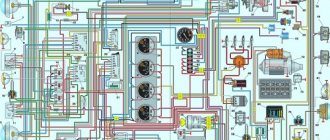
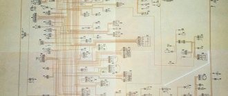
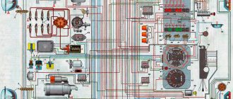
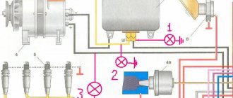
Electrical wiring diagram
The top picture shows a non-contact version of the car's electrical wiring in color; the bottom picture shows an older model.
Old style UAZ 3303 wiring diagram
The electrical circuit of the UAZ 3303 generator shown separately is shown above.
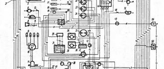
The circuit having an ignition system with contacts is taken from 469. There is a radio receiver on the circuit, this is interesting.
Electrical circuit of UAZ 469 similar to 3303 with contact ignition system
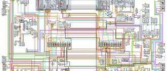
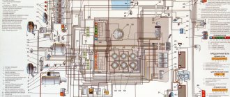
In conclusion, I present another one from an onboard UAZ 33036 that is newer, but not yet fuel-injected.
Electrical circuit diagram of UAZ-3303.
Electrical circuit diagram of UAZ-3303.
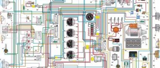
Electrical circuit diagram.
1 – front lamp; 2 – headlight; 3 – heater fan electric motor; 4 – sensor for warning lamp of emergency condition of hydraulic brake drive; 5 – sound signal; 6 – washer motor; 7 – cabin light switch; 8 – cabin lighting; 9 – warning lamp for turning on the parking brake system; 10 – switch for the parking brake system warning lamp; 11 – windshield wiper motor; 12 – switch for the electric motor of the windshield wiper and washer; 13 – speedometer; 14 – signal lamp for turning on the high beam headlights; 15 – voltmeter; 16 – oil pressure indicator; 17 – warning lamp for emergency oil pressure; 18 – coolant temperature indicator in the engine cylinder block; 19 – warning lamp for emergency overheating of the coolant in the radiator; 20 – fuel level indicator; 21 – alarm switch; 22 – cigarette lighter; 23 – cigarette lighter fuse; 24 – signal lamp for direction indicators; 25 – emergency warning lamp for the hydraulic brake system; 26 – ignition switch; 27 – central light switch; 28 – thermal fuse; 29 – heater resistance; 30 – heater fan motor switch; 31 – headlight switch; 32 – rear fog lamp switch; 33 – fuse block; 34 – plug socket; 35 – unbalance solenoid valve; 36 – direction indicator switch; 37 – sound signal button; 38 – sensor for emergency oil pressure warning lamp; 39 – warning lamp sensor for emergency overheating of the coolant in the radiator; 40 – oil pressure indicator sensor; 41 – coolant temperature indicator sensor in the cylinder block; 42 – turn signal switch; 43 – heater fuse; 44 – heater fan motor switch; 45 – resistance of the heater fan motor switch; 46 – heater fan electric motor; 47 – generator; 48 – spark plug; 49 – sensor-distributor; 50 – ignition coil; 51 – ground switch; 52 – rechargeable battery; 53 – fuel level indicator sensor in the tank; 54 – transistor switch; 55 – emergency vibrator; 56 – electronic carburetor control unit; 57 – microswitch; 58 – additional resistance; 59 – additional starter relay; 60 – solenoid valve; 61 – starter; 62 – fuel level indicator sensor in the tank; 63 – fuel tank sensor switch; 64 – brake signal switch; 65 – reverse light switch; 66 – rear lamp; 67 – rear fog lamp; 68 – license plate light; 69 – reversing lamp.
Source