Repair
,
maintenance
and
installation
,
repair of the clutch of a KAMAZ vehicle
.
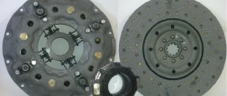
The driven clutch disc is installed on a press and the rivets securing the friction linings to the clutch disc are pressed out, after which the friction linings are removed. The driven disk is checked for warpage. The 0.2 mm thick feeler gauge must not pass between the surfaces of the disc and the surface plate. The width of the spline groove of the hub hole should not exceed 6.05 mm.
Friction linings should be replaced as a set. The thickness of the linings should be 4.5 mm, and the total thickness of the disk with the linings installed on it should be 11 mm. In the overlays along the jig, holes with diameters of 4.2 and 9.5 mm are drilled and countersinked to a depth of 2.0 (-0.15; -0.10) mm. Having aligned the holes of the friction linings with the holes of the driven clutch disk so that each hole in the disk corresponds to a hole with a diameter of 4.2 mm in one lining and 9.5 mm in diameter in the other, press the linings to the disk with a clamp and rivete them on the press on both sides. The runout of the working surfaces of the friction linings should not exceed 0.5 mm at a radius of 137 mm from the center of the disk.
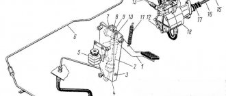
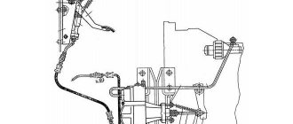
Rice. 7.1. Pressure disk assembly with casing: 1 — stand (stand); 2 - bolt; 3 — adjusting nut; 4 — locking plate; 5 — thrust ring; 6 — coupling bolt
The clutch housing assembly with the pressure plate is installed on the stand and the pressure springs are compressed using the stand devices. Having bent the whiskers of the locking plates 4 (Fig. 7.1), unscrew the bolts 2 securing the locking and support plates of the adjusting nuts 3 and remove the plates. After removing the lock washers of the adjusting nuts, unscrew the adjusting nuts. Having unscrewed the coupling bolts 6 (MlОх 1.25×65) from the pressure plate, remove the clutch cover from the stand.
Then, sequentially remove the thrust ring 16 (see Fig. 5.3) of the pull-out levers, the hinges 11 of the thrust ring springs, the pressure springs 18, washers and linings of the pressure springs from the clutch pressure plate. The lock washers are removed from the axis of the pull-out levers 8 of the pressure disk, press out the axles and remove the levers assembled with the forks 7 and the pull-out springs of the thrust ring and the pressure disk 5.
Having removed the lock washers from the fork axes of the 7 pressure disk levers, press out the axles, remove the springs, disconnect the forks from the pressure disk levers and remove the needle rollers from the holes in the levers.
The removed parts are washed, blown with compressed air and defective.
The clutch casing is rejected if there are cracks more than 20 mm long, dents with a depth of 1 mm or more, deformation of the mating plane of the casing to the flywheel (if a 0.3 mm thick probe passes between the surface being checked and the surface plate), if the guide surfaces for the pressure springs are worn to the thickness walls less than 5.5 mm and spherical surfaces for adjusting nuts up to a thickness of less than 3.1 mm. The worn M8x1-6N thread is restored.
The driven clutch disc is rejected when the hole for the hub is worn to a diameter of more than 96.2 mm, the windows for the damper springs are worn to a diameter of more than 30.9 mm, breaks, cracks, burnt or worn out friction linings, when the sinking of the rivet heads is less than 1.7 mm, when the non-flatness of the friction surfaces is more than 0.25 mm, their runout is more than 0.5 mm, and the width of the hub spline hole is more than 6.1 mm. When the rivets securing the friction linings are loosened, the rivets are crimped or replaced.
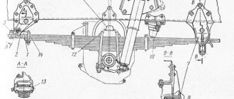
Rice. 7.2. Clutch release fork
The clutch release fork (Fig. 7.2) is rejected if there are breaks or cracks, uneven wear of the supporting spherical surfaces of the legs (if size b is less than 21.5 mm), wear of the side surfaces of the legs (if size a is more than 85.24 mm), deformation of the fork ears under the tightening bolt (if size e is less than 2.4 mm) and repaired when the keyway is worn to size c more than 6.08 mm, thread A is damaged or worn.
The clutch release clutch is rejected if there are cracks or breaks, broken spring supports, wear of the journal for the release bearing to a diameter of less than 70.0 mm, and wear of the holes for the clutch crackers to a diameter of more than 10.058 mm.
The clutch release fork shaft is rejected if there are cracks or breaks, crushed or broken splines, wear of the splines (when the size of the rollers with a diameter of 1.157 mm inserted into the spline cavities is less than 26.193 mm), wear of the journals under the clutch housing bushing and the clutch release fork to a diameter of less than 24.74 mm, wear of the keyway in width to a size greater than 6.09 mm and bending (if the radial runout of the outer cylindrical surface relative to the axis of the part exceeds 0.3 mm).
The clutch release fork shaft lever is rejected if there are cracks, chips, breaks and deformation of the lever ears, if the distance between them is less than 5.0 mm. The torn thread is restored.
Rice. 7.3. Middle disc release lever
The release lever of the middle clutch disc (Fig. 7.3) is rejected if there are cracks or breaks, breakage of the protrusion surface C, deviation of the radius of curvature of surfaces B from 10 mm, wear of the surfaces of the tabs B (if size a is less than 48.5 mm). If the hole is worn to a diameter d of more than 16.35 mm, it is restored.
The release lever bushing is rejected if the outer diameter is worn to a size of less than 15.9 mm and the hole to a diameter of more than 13.11 mm.
The clutch housing is rejected if there are cracks in the areas of attachment to the flywheel housing and the gearbox housing, the mounting of the power unit support, and if the holes are worn: under the clutch fork shaft bushings - up to a diameter of more than 31.09 mm (before measurements, loosening of the bushings is detected by light blows of a hammer ); in bushings under the clutch release fork shaft - up to a diameter of more than 25.12 mm; under the input shaft bearing cover - up to a diameter of more than 200.073 mm.
If the studs are loosened, installed during testing by hand, and if the threaded holes are damaged, the clutch housing is repaired.
The clutch pressure plate is rejected if there are cracks or chips, scuffs, marks and runout of the working surface of more than 0.07 mm, as well as wear of: the disk in thickness - to a size less than 24.2 mm; grooves for levers in width - up to a size of more than 12.3 mm; protrusions in width - up to a size of less than 59.50 mm; holes for the lever axis up to a diameter of more than 10.85 mm.
The clutch pressure plate release lever is rejected if there are cracks or chips and if there is wear: the thickness of the lever in the hole area is less than 11.8 mm; holes for needle bearings - up to a diameter of more than 15.2 mm; working surface of the foot - up to a width of less than 8.6 mm.
The middle drive disk of the clutch (Fig. 7.4) is rejected if there are cracks, chips or scuffs, wear of the protrusions to size a is less than 59.5 mm, wear of the disk thickness to size b is less than 24.2 mm, non-flatness of surfaces A and B is more than 0 .07 mm. Worn threads are restored.
Needle rollers are rejected if there are signs of corrosion and dents on the surface.
When assembling the clutch housing with the pressure plate, needle rollers are installed in the holes of the pull-out levers 8 (see Fig. 5.3) using technological fingers, having previously lubricated them with grease “C”. 20 rollers are installed in each hole. Then the levers are connected to the forks 7, the axles of the forks are pressed in, the pull-out springs 13 of the thrust ring of the levers are installed and the lock washers are put on the axes of the forks of the levers.
The pressure plate is subjected to static balancing to an imbalance value of no more than 0.03 N • cm (30 gf • cm) and installed on a stand. The pull-out levers 8, assembled with forks 7 and springs 13, are inserted alternately into the slots of the pressure plate brackets. In the combined holes of the levers and brackets, pushing out the technological fingers, insert the axles of the levers and put lock washers on them.
Clutch model "17." for engines 740.13-260 clutch pressure disc
CLUTCH DISC DEFECTIVE MAP
Clutch push disc
Uneven wear, scoring, burns on the friction surface
Process until traces of defects are removed
General wear, scoring and burns on surface B
remove by flat grinding until defects are removed, while the thickness of the disc should not be less than 53.0 mm.
The presence of hairline cracks on surface B
is not a rejection sign.
When flat grinding, base the part on a magnetic table in a fixture relative to surface D
or on disk
table E.
When balancing, the disk is mounted on a mandrel with surface D
, then balance with an accuracy of 30 g x cm, drilling holes along the periphery of surface
E
with a depth of no more than 10 mm with a distance between centers of at least 19 mm.
RICE. 32. DEFECTS IN THE CLUTCH DISC
Specifications:
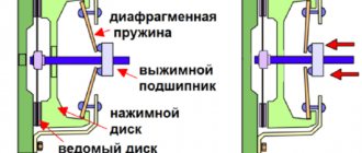
- Clutch type: friction, dry double-disc with peripheral pressure springs
- Transmitted torque, N*m (kgcm): 833 (85)
- Number of rubbing surfaces: 4
- Diameter of friction linings, mm: outer: 350; internal: 200
- Thickness of the driven disk with linings, mm: 11
- Overlay thickness, mm: 4 5
- Number of compression springs: 24
- Spring force with clutch engaged, N (kgf): 13150. 15300 (1315. 1530)
- Spring force with clutch disengaged, N (kgf): 14090. 16200 (1405. 1602)
- Number of pressure plate release levers: 4
- Drawbar gear ratio: 4.85
- Type of torsional vibration damper: spring-friction
- Clutch drive: hydraulic, with pneumatic booster
- Membrane type tracking device.
Middle clutch drive disc
DEFECTIVE MAP OF THE MIDDLE CLUTCH DISC
Clutch drive disc
Wear of the surfaces of the studs mating with the surfaces of the flywheel grooves
Uneven wear, scoring, burns on the friction surface
Process until defects are removed
Chip or break on the unloaded side of the tenon
Shear, break from the loaded side of the tenon
RICE. 33. DEFECTS OF THE MIDDLE CLUTCH DISC
The worn surface of the tenon is fused in carbon dioxide with PANCH-11 wire and milled to size 95 (Fig. 33).
Surfaces B
and
B
are ground on a surface grinder until wear is removed with a generous supply of coolant.
In this case, the thickness of the disk should not be less than 28 mm, non-flatness of surfaces B
and
C
is allowed up to 0.07 mm, and non-parallelism of these surfaces up to 0.1 mm.
The presence of hairline cracks on surfaces B
and
C
is not a rejection sign
.
The restored part is subjected to static balancing in the assembly with an automatic adjustment mechanism. The part is mounted on a mandrel with surface D
and balance with an accuracy of at least 30 g x cm, drilling holes on the surface
D1
with a depth of no more than 10 mm with a distance between centers of at least 19 mm.
Purpose of the KAMAZ clutch
KAMAZ clutch (pressure clutch, clutch release clutch, clutch release bearing clutch) is a clutch unit for trucks of the Kama Automobile Plant equipped with a manual transmission; an actuator for the clutch drive, which ensures that it is turned off (by pressing the pressure/drive plate away from the driven one) at the moment of disengaging and engaging gears.
Most KAMAZ truck models are equipped with gearboxes of domestic and foreign production - “native” KAMAZ units of the 14th and 15th model series and German ZF gearboxes. Various gearboxes, depending on the type, are equipped with a friction clutch of domestic production or the German company ZF Sachs. All types of these mechanisms have one part that ensures a normal break in the flow of torque when selecting gears - the clutch.
The KAMAZ clutch solves several problems:
- Acts as a load-bearing element for fixing the release bearing, preventing its distortions and displacements;
- Ensures normal transmission of force from the clutch release drive parts to the release bearing;
- Protects the bearing from shock loads, wear and other negative factors.
Despite the fact that the clutch is small in size and has a fairly simple design, the role of this link in the functioning of the entire transmission cannot be overestimated - if it breaks down, the clutch may not work correctly or even fail. Therefore, a worn, deformed or worn coupling should be replaced, and to select this part correctly, it is necessary to understand the types of KAMAZ couplings used, their design features and characteristics.
Grip characteristics of Kamaz-14, Kamaz-142
The Kamaz clutch is designed to ensure a smooth start of the vehicle and disconnect the engine from the transmission when changing gears.
In power units with Kamaz engines, two models are used: clutch 14 or clutch 142.
Kamaz 14 clutch and its technical characteristics
The clutch control drive is hydraulic with a pneumohydraulic booster, there is a tracking device.
The pressure disk consists of the following main parts:
— disk diameter Ø=350mm — lining thickness S=4.5mm. — there are 10 splines on the hub, internal diameter 34mm. — two discs are installed on the clutch with hubs with a long end facing each other.
Has a heat-resistant friction lining with a long service life.
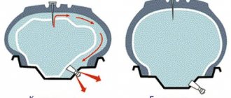
To ensure ventilation of the Kamaz clutch, better heat removal and weight reduction, windows are made in the disk body, separated by internal ribs.
The cleats house a lever mechanism that mechanically adjusts the position of the middle disc when the clutch is disengaged to ensure clean disengagement.
Each tenon on the side of the casing has a boss in which a groove is made and two holes are bored to install the axis of the clutch release lever.
The clutch basket casing (pressure disk) has 12 recesses for installing springs and holes for installing lever forks.
The disk has eight windows for the damper springs. Along the periphery of the disk, friction linings made of asbestos composition are riveted on both sides with rivets.
The hub has internal splines that are installed on the splines of the gearbox input shaft. The hub also has eight windows for the damper springs. The damper serves to dampen torsional vibrations that occur in the engine and transmission.
Due to the uneven operation of the engine and the elasticity of the Kamaz crankshaft, constant twisting and unwinding of the shaft occurs, i.e. own torsional vibrations arise. The transmission of a Kamaz vehicle contains shafts of a gearbox, transfer case, cardan transmission, and axle shafts.
Technical characteristics and clutch parameters of Kamaz 142
The clutch control drive is hydraulic with a pneumohydraulic booster, there is a tracking device.
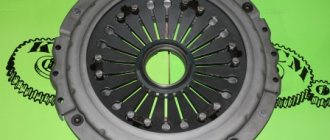
Clutch pressure plate (basket) KamAZ 142
Clutch disc KamAZ 142 leading middle
When the Kamaz-142 clutch is abruptly engaged, the vehicle is braked without disengaging the clutch, or when the wheels hit an obstacle, forced vibrations occur in the transmission shafts.
If the engine operates unevenly, torsional vibrations from the engine can be transmitted to the transmission. This is especially dangerous when the frequency of natural angular vibrations of the transmission coincides with the frequency of torsional vibrations. In this case, resonance occurs and the load on transmission parts increases sharply, which can lead to their breakdown.
Forced torsional vibrations in the transmission, in turn, can be transmitted to the engine, which sharply increases the load on its parts.
The elastic element serves to change the vibration frequency of the shafts and prevent the phenomenon of resonance, i.e. coincidence of frequencies of natural angular vibrations and torsional vibrations, and consists of eight cylindrical springs.
The friction element reduces the amplitudes of forced vibrations, converting vibration energy into heat, and consists of two cages, two disks, and two friction rings.
Damper discs and cages are riveted to the hub flange on both sides. Friction rings are riveted to the driven disc of the Kamaz-142 clutch on both sides.
The friction rings and damper disks also have eight windows each; the windows for the springs coincide with the windows in the driven disk and the hub flange. Eight coil springs are installed in the windows.
When torsional vibrations occur, the hub of the driven disk rotates relative to the disk itself; The damper springs, compressing, change the oscillation frequency, ensuring that the frequencies of the transmission's natural oscillations and forced torsional oscillations do not coincide, i.e., they prevent the phenomenon of resonance.
When the hub turns, the damper discs slide along the friction rings, and due to friction, the vibration energy is converted into heat.
The Kamaz-142 clutch release mechanism consists of four release levers, a thrust ring, a clutch release clutch with a release bearing, a clutch release fork with a shaft, and two release springs.
Four release arms are installed on the clutch pressure plate (basket) and connected to the housing using forks. The pull-off levers are connected to the pressure plate and pin forks. The pins are installed in the disc and forks on needle bearings.
A thrust ring spring is installed on the lever axis in the fork, which with one tendril rests against the casing, and with the other, through a loop, constantly presses the thrust ring against the pull-out levers.
The thrust ring protects the release levers (KAMAZ-142 clutch pads) from wear. To disengage the clutch, a clutch release clutch with a bearing assembly is installed on the cover of the gearbox input shaft.
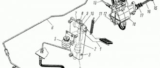
The Kamaz clutch, under the action of springs, is constantly pressed by the crackers pressed into it to the legs of the clutch release fork. To lubricate the clutch and bearing, a lubricant supply hose and an oiler are installed on the clutch housing.
GAZelle clutch disc sizes
There are two sizes on light commercial vehicles of the GAZ Group of the Next, Business and Sable model ranges: 240mm and 280mm. In most cases the disc will be 240mm from the kits:
- 3000950069;
- 3000950503;
- 3000951401.
The most common confusion lies in the GAZelle NEXT clutch with the Cummins 2.8 engine. For a regular gearbox, disc 1878006095 (1878005456) with a diameter of 240 mm is installed, and for a reinforced manual transmission – 1878008502 (A21R22.1601130) from kit 3400700645, whose size will already be 280 mm.
Sometimes even experts won’t tell you exactly what kind of disc is needed for a Gazelle Next with Cummins engines, so knowing the size, you definitely won’t buy a spare part that won’t fit your car.
How to select and replace the KAMAZ clutch correctly
During vehicle operation, the clutch coupling is subjected to significant loads, as a result of which it wears out intensively and can receive various damages. Clear signs of clutch wear are a change in the travel of the clutch pedal and deterioration in clutch performance, and if the clutch (or just its bearing) is deformed or destroyed, increased noise from the clutch is also observed. In all these cases, it is necessary to perform diagnostics (visually assess the condition of the unit) and replace the faulty part.
For replacement, you should only select the type of clutch that is suitable for the clutch installed on the vehicle. For trucks under warranty, it is recommended to take original parts; for older vehicles, you can use less expensive analogues - today there are quite a lot of them on the market and there is plenty to choose from. If necessary, you should also buy related parts - crackers (if they are provided for in the design, but are not included in the kit), a lubricant supply hose, sets of thrust and locking rings, etc.
Replacing the clutch must be carried out in accordance with the vehicle repair instructions. Working with different types of clutches has its own characteristics, but in any case it requires dismantling the gearbox and performing a number of auxiliary operations. The easiest way to change the clutch coupling of model 142 and similar ones is to remove this part from the gearbox shaft and install a new one in its place (it is necessary to connect the lubricant supply hose). In pull-out clutches, the task of replacing the clutch is somewhat more complicated, since in this case the old part must first be disconnected from the diaphragm spring, and a new one installed in its place. To dismantle the coupling, it is necessary to remove the locking ring by approaching it from the back side of the spring. Installation of a new clutch in the MFZ-430 clutch is carried out only after installing the gearbox; for this, the part is brought to the diaphragm until it clicks with a crowbar through a special hatch in the clutch housing (“bell”). In the model 19 clutch, the clutch is first mounted on the basket, this assembly is installed on the flywheel, after which the gearbox is brought in and secured.