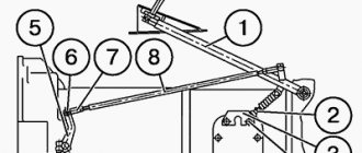
No less than 195 mm - this is the full travel of the clutch pedal. It should be adjusted using the adjusting limiter bolt 11 (Fig.) of the clutch pedal travel.
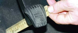
The free travel of the clutch pedal should not go beyond 50-60 mm. By pressing the pedal with your hand, the value of the clutch free pedal travel is determined, while there should be no air pressure. The beginning of switching off is felt by a strong increase in force.
The free stroke is adjusted by changing the length of the rod 21. To change the length, you need to: disconnect the rod 21 from the lever 20. Loosen the lock nut of the rod fork, unscrew the fork to increase the free stroke, or tighten it to reduce it. Connect the rod to the lever. Tighten the fork locknut. Check the free travel of the pedal.
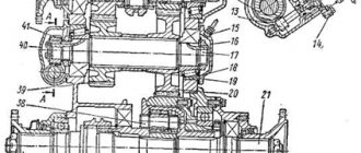
If the thread of the rod is completely used, then move lever 20 to one slot. Next, by removing the hatch cover of the upper crankcase 4 (Fig.), make sure that the legs of the clutch release fork 14 confidently rest against the cracks of the clutch 13. You can check through the hatch from below.
While using the machine, the following common clutch breakdowns may occur: clutch slipping (not fully disengaged); the clutch may “drive” (not fully disengaged).
If the clutch is not fully engaged when the engine speed increases, then the car (with the clutch pedal released) either does not completely move away, or the speed of the car increases very slowly. At the same time, the smell of burnt linings of friction driven discs is clearly felt in the cabin.
Clutch pedals URAL 4320 5557: adjusting full and free play
No less than 195 mm - this is the full travel of the clutch pedal. It should be adjusted using the adjusting limiter bolt 11 (Fig.) of the clutch pedal travel.
The free travel of the clutch pedal should not go beyond 50-60 mm. By pressing the pedal with your hand, the value of the clutch free pedal travel is determined, while there should be no air pressure. The beginning of switching off is felt by a strong increase in force.
The free stroke is adjusted by changing the length of the rod 21. To change the length, you need to: disconnect the rod 21 from the lever 20. Loosen the lock nut of the rod fork, unscrew the fork to increase the free stroke, or tighten it to reduce it. Connect the rod to the lever. Tighten the fork locknut. Check the free travel of the pedal.
If the thread of the rod is completely used, then move lever 20 to one slot. Next, by removing the hatch cover of the upper crankcase 4 (Fig.), make sure that the legs of the clutch release fork 14 confidently rest against the cracks of the clutch 13. You can check through the hatch from below.
While using the machine, the following common clutch breakdowns may occur: clutch slipping (not fully disengaged); the clutch may “drive” (not fully disengaged).
If the clutch is not fully engaged when the engine speed increases, then the car (with the clutch pedal released) either does not completely move away, or the speed of the car increases very slowly. At the same time, the smell of burnt linings of friction driven discs is clearly felt in the cabin.
Slipping of driven disks: reasons
- There is no gap between the thrust ring and the clutch release clutch bearing when the clutch pedal cavity is released. If there is no gap, then the pressure disk is not pressed completely against the driven disk. To eliminate this malfunction, the gap between the thrust ring and the clutch bearing must be restored by checking and adjusting the free travel of the clutch pedal;
- The clutch discs became oily because the lubricant penetrated into the clutch housing through the seals at the end of the rear crankshaft of the engine or the primary shaft of the gearbox, as well as during the excess lubrication of the clutch release bearing. When a lubricant gets on the disc friction surfaces, they slip. It is necessary to remove the clutch and wash the discs with gasoline;
- The friction linings and friction surfaces of the flywheel are worn out, the pressure and middle drive disks are worn out. If there is slight abrasion of the linings, the fault can be eliminated by adjusting the free travel of the clutch pedal; worn parts should be replaced if there is increased abrasion of the linings, friction surfaces of the discs and the flywheel;
- The pressure springs have broken or become weak. Replace springs.
Incomplete shutdown
Difficulty shifting gears indicates incomplete disengagement of the clutch. It is accompanied by impacts of the teeth of the transmission gears. Probable reasons:
Clutch debugging
The next stage of adjustment will be to adjust the free play parameters of the clutch, the value of which should be from 3.2 to 4 mm. The measurement is carried out by rotating the adjusting nut.
The sequence of actions in this case:
- Loosen the fork mounting nut.
- Unscrew the fastening pin, allow it to move freely and remove it.
- Rotate the traction fork until the required clearance is obtained.
- Tighten the nut and install the pin in place.
- Install the locking pin.
- Check the setting. When the pedal is fully depressed, the clutch stroke should be at least 25 mm.
Production of trucks and chassis of the Ural-4320 line began on November 17, 1977 [1] and in fact this series is still being produced today, albeit in a significantly modernized form.
The main difference between the Ural-4320 and the carburetor Ural-375D line is the economical and high-torque diesel engine. Fuel consumption per 100 km is slightly less than 30 liters versus 48 liters. As of 1986, more than a million trucks were produced. Initially, the Ural-4320 was equipped with a KamAZ-740 diesel engine, but as a result of a fire at the KamAZ engine plant on April 14, 1993, supplies of this engine to third-party manufacturers ceased, and engines began to be installed on the Ural-4320 (as well as all subsequent models and modifications of Ural trucks). YaMZ-236 and YaMZ-238 Yaroslavl Motor Plant. Due to the resulting shortage of diesel engines, some of the Ural-4320 produced in 1993-1994. was forced to be equipped with a ZIL-375 carburetor engine, that is, the production of the Ural-375D model was actually extended, but with a type 4320 engine compartment tail. Initially, modifications with the YaMZ-238 engine were distinguished by an outwardly longer engine compartment, while cars with the YaMZ-236 engine retained the same engine compartment as that of vehicles with a KAMAZ-740 engine (the difference is that vehicles with YaMZ-236 have an air filter on the right wing due to a different, more dense layout of the engine compartment). Since the mid-2000s, all cars, regardless of engine model, have been produced with an extended engine compartment.
Clutch adjustment Ural 4320 diagram
Adjusting the clutch and its drive
Clutch adjustment may be required if individual worn parts are replaced before installing the clutch on the engine. This checks the position of the release lever thrust ring to ensure that all release levers operate simultaneously and are in the correct position relative to the pressure plate. To check, the pressure disk assembly with the casing and shutdown levers is installed on a control stand or on a flywheel with an insert that provides an installation dimension of A = 28.9...29.1 mm. Dimension B should be equal to 51.7...52.3 mm, and the runout of the end T2 of the thrust ring relative to the end should not be more than 0.2 mm. If the position of the thrust ring is violated, adjustment must be made using the adjusting nuts until size B is restored within the required limits. When tightening the adjusting nuts, size B increases, and when unscrewing, it decreases. After installing the clutch on the engine, the runout of the end of the thrust ring should not exceed 0.5 mm.
Dismantling process
When repairing components of the Ural 4320, you should take into account: removing the front axle gearbox differs from the rear axle in that it is removed from the vehicle upon completion of dismantling.
After dismantling and installation on stands, the Ural gearbox is removed in the following way:
- disconnect the brake hoses, steering linkage rod, elements of the sealing device;
- unscrew the nuts connecting the ball joints;
- a mounting blade will help in dismantling the steering knuckle assemblies;
- We remove the entire side cover of the gearbox housing with an oil supply type fitting;
- unscrew the bolts and nuts holding the crankcase together with two bolts located inside;
- Using a device for lifting the load, we remove the unit itself from the axle housing.
Clutch repair Ural
Dismantling and disassembling the clutch of a Ural car. To remove the clutch, you must remove the gearbox. Before disassembling, make sure there are “O” marks on the flange of the clutch housing, on the narrow spike of the middle drive plate and on the flywheel protrusion. These marks are placed at the factory after joint balancing of the pressure plate assembly with the casing, as well as the crankshaft with flywheel and clutch assembly. If there are no marks, then put marks and align them during assembly.
Belts for Yamz 236 engine
OJSC Avtodizel, known to many as the Yaroslavl Motor Plant YaMZ, produces high-quality spare parts for many cars of different models and brands. It is also one of the largest enterprises in Russia, which not only produces, but also develops a wide range of diesel engines. Clutches, gearboxes and spare parts for them are also manufactured here.
Ticket No. 12
All topics in this section:
Ticket No. 1 1. Design and operation of the transfer case of the Ural-4320 car. On the Ural-4320 car, a mechanical two-stage transfer case with an asymmetrical cylinder is installed.
Purpose of the transfer box On the Ural-4320 car, torque from the gearbox is transmitted to the transfer box, which serves to distribute torque torque between the front drive axle and the two drive axles
Ticket No. 2 1. Purpose, design and maintenance of the KAMAZ-4310 cardan transmission. The driveline is part of the vehicle's transmission. It transmits torque
Ticket No. 3 1. Brake chambers KAMAZ 4310 purpose, design and operation. Brake chambers are designed to convert compressed air pressure into the forces required to drive
Ticket No. 4 1. Gearbox of the Ural-4320 car. This car has a five-speed gearbox with constant mesh gears on all fronts.
Ticket No. 5 1. Purpose, design and operation of the URAL-4320 crank mechanism. Crank mechanism (CSM) - designed to absorb gas pressure in the cylinders and
Responsibilities of a military driver The driver is responsible for maintaining the vehicle assigned to him, ensuring that it is in good condition and ready for use. He is obliged to: - have a firm knowledge of the device, technical capabilities
Ticket No. 6 1. Purpose, design and operation of the KAMAZ-4310 clutch. The clutch is friction, dry, double-disc with peripherally located pressure springs. Presenters and
Ticket No. 7 1. Coolants and requirements for them. Descaling solutions. Brands “40” and “65” are used as coolant for KamAZ and Ural vehicles - antifrost.
Ticket No. 8 1. Fill the engine lubrication system with oil, check its level and pressure. Checking the oil level in the engine sump is done when the car is level.
Ticket No. 9 1. Purpose, design and operation of the centrifugal oil filter in the lubrication system of the URAL-4320 engine. The centrifugal oil filter consists of: a housing; tubes o
Ticket No. 10 1. The order of cars leaving the park and returning them to the park. Vehicles are released from the fleet according to the order approved the day before by the unit commander, and are technically in good working order.
Ticket No. 11 1. Starter. The starter is a series-excited DC electric motor of a closed design and converts electrical energy into an accumulative
Ticket No. 13 1. Purpose, design and operation of the air filter of the URAL 4320 car engine. The dry-type two-stage air filter is installed on the left side member of the frame. He
Ticket No. 14 1. Removing cars from storage. Machines in short-term storage are removed according to the operation plan. Long-term storage vehicles are allowed to be removed
Do not remove the rotor during maintenance - assemble the filter in the reverse order, align it with the marks on the cap in the rotor, check the condition of the cap sealing gasket, and replace the gasket if necessary. Before installation
Ticket No. 15 1. Fuel pump high pressure maintenance main faults of the URAL 4320. The high pressure fuel pump (HPF) is installed in the camber of the engine cylinder block
Ticket No. 16 1. General design of the internal combustion engine power system. The power supply system is designed for storage, preparation and supply of fuel.
Ticket No. 17 1. Purpose, design and operation of the diesel engine power system. Engine. This is the source of mechanical energy necessary to move the car.
Ticket No. 18 1. The generator on the car serves to supply electric current to all consumers while the engine is running and recharging the battery. The generator consists of a rotor, stat
Ticket No. 19 1. Unscrew the battery plugs and clean the ventilation holes in them. Check the integrity of the cans and battery surface (no cracks or leakage of electrolyte)
Ticket No. 20 1. Purpose, design and operation of the cooling system of the KAMAZ-4310 vehicle. The cooling system is designed to maintain the normal thermal state of the engine during
Ticket No. 21 1. The main gear is installed on the axle housing through a 0.8 mm thick paronite gasket and secured with thirteen bolts and two studs. Eleven bol
Ticket No. 22 1. Malfunctions of drive axles, their symptoms, causes and solutions, maintenance of drive axles. Signs of malfunction of the drive axle mechanisms are higher
Ticket No. 23 1. The crankshaft speed regulator is designed to maintain a given speed by changing the amount of fuel supplied to the cylinders, depending on the
Ticket No. 24 1. Tire sizes and designations. Standard air pressure in tires The KamAZ-4320 vehicle is equipped with wide-profile tires measuring 1220 x 400 - 533. The first digit in this
Ticket No. 25 1. Check the condition of the springs on the KAMAZ 4310 vehicle, carry out fastening and lubrication work on them. Tightening the nuts of the spring ladders should be carried out with the vehicle loaded.
Ticket No. 26 1. Motor oils are used to lubricate the rubbing parts of engines. Oils must have optimal viscosity, good lubricating and washability, and high anti-corrosion properties.
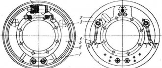
Ticket No. 27 1. Brake mechanism of the KAMAZ-4310 vehicle. Basic malfunctions and ways to eliminate them. Brake mechanisms - shoe, drum type, with fixed supports, with
Ticket No. 28 1. Purpose, design and operation of the oil radiator and the procedure for including it in the car’s lubrication system. To cool the oil, the system is sometimes equipped with a radiator. Maslyan
Ticket No. 29 1. The parking brake system serves to hold it motionless relative to the supporting surface. Parking brake system of the URAL 4320 vehicle (Fig. 4)
Ticket No. 30 1. Purpose, design and operation of the disconnect valve and the connecting head of the brake drive of the KAMAZ-4310 vehicle. Prednaz diaphragm type isolation valve
Ticket No. 31 1. Before lifting the car on a jack, you must place the car on a horizontal surface. If this cannot be done, then you need to park the car at some reliable place.
Ticket No. 32 1.Quantity. Name of the lubricant. Grease lubrication points. Main brands, duplicate brands. The manual control rod for stopping the engine is 0.003 kg litol-24. Lubricant
Ticket No. 33 1. The gear shift mechanism consists of three rods with forks; three ball retainers, a locking device and a safety device against accidental engagement of first gear and
Ticket No. 34 1. Shock absorbers are used to quickly dampen frame vibrations. Modern trucks are equipped with hydraulic telescopic shock absorbers.
The procedure for leaving cars from the park and returning them to the park The use of cars is planned taking into account the provision to drivers of the necessary time to service the cars, prepare them for the trip and rest. The production of vehicles not provided for in the order is carried out
Ticket No. 35 1. The winch is used for self-pulling a car, providing assistance to other stuck equipment, and can also be used to lift and lower loads. Lebe drive
Self-switching of gears while the vehicle is moving. The causes of the malfunction may be: - incomplete engagement of the gear due to a malfunction of the shift mechanism clamps, wear of the fork legs or nuts, loosening of the forks and lever
The procedure for issuing a waybill The waybill is assigned a number, the date of its issue and the name of the organization are indicated (address and telephone number are also possible). In the lines provided for information about the driver
Ticket No. 37 1. The generator on the car serves to supply electric current to all consumers while the engine is running and recharge the battery, compensating for consumption
Removing machines from storage Machines in short-term storage are removed according to the operation plan. Long-term storage vehicles may be removed by special written order. About removing vehicles from storage
Ticket No. 39 1 Braking mechanisms are used to create artificial resistance to movement. On trucks, drum and shoe brake mechanisms with internal
Ticket No. 40 1.. The compressor ensures the creation of a reserve of compressed air in the brake system. The URAL-4320 uses a two-cylinder piston compressor.