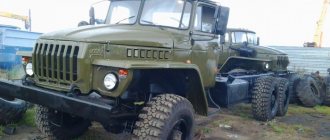
The URAL truck is a very reliable vehicle and rarely fails. But even she sometimes has breakdowns. There is a very unpleasant situation when the URAL engine stalls and does not want to start. At the same time, a message with a corresponding description of the fault code appears on the instrument panel display. But there are exceptions when errors are not displayed. Our company’s specialists have accumulated solid experience in diagnosing and repairing the described faults. There are two radically different options for not starting the engine:
- When you turn the key in the ignition, the starter cranks the excavator engine
- The starter does not turn on and does not turn the engine
I will try to tell you in more detail about each of the options for equipment malfunction.
Preheater
► Malfunction: Overheating of the heater boiler, water escaping through the filler neck of the heater
Probable cause: Formation of ice plugs in the supply pipes due to non-compliance with the instructions for completely draining the water or improper use of the heater. No circulation
Remedy: Warm the pipes by periodically turning the heater on and off at intervals of 2-3 minutes, pouring hot water over the outside of the pipes
► Malfunction: The heater does not start
Probable cause:
The electric motor of the pump unit does not rotate:
- freezing of the fan impeller due to incomplete removal of water from it after washing the car or fording
Remedy: Warm the fan and liquid pump housing using improvised means
Probable cause:
The electric motor of the pump unit does not rotate:
- freezing of the liquid pump impeller due to non-compliance with the instructions for draining water from the cooling system.
Remedy: Warm the fan and liquid pump housing using improvised means
Probable cause: Open circuit in the high voltage source
Remedy: Check and tighten the terminal connections of the current supply wires
Probable Cause: High voltage source is not working
Remedy: Disconnect the high voltage wire and secure its end at a distance of 3-5 mm from the ground of the car, if there is no spark when turning on the spark plug, replace the high voltage source
Probable cause: Spark plug not working
Remedy: Clean or replace spark plug
Probable cause: The solenoid valve does not operate (there is no click when the solenoid valve is turned on). The fuel filter in the solenoid valve or injector is clogged. Injector is clogged.
Remedy: Disassemble the nozzle, wash the parts in kerosene or acetone. Assemble the nozzle and check the quality of atomization without screwing the nozzles into the burner
► Malfunction: The heater smokes or throws out flames
Probable cause: Fuel pump adjustment is out of order
Remedy: Reduce fuel consumption by adjusting the fuel pump pressure reducing valve
Probable cause: Low speed of the electric motor shaft
Remedy: Charge the battery, check the serviceability of the electric motor
► Malfunction: Prolonged warm-up of the engine, unstable combustion of the heater
Probable cause: Low fuel supply due to clogged injector filter, leaking fuel lines, improper fuel pump adjustment
Method of elimination: Wash the filters, injector, and eliminate leaks in the fuel lines. Adjust the fuel pump pressure reducing valve
Brakes do not light up Ural 4320
The main task of diagnosing a machine can be called identifying breakdowns of the Ural-4320 brake system and correcting them in a timely manner.
Let's consider the sequence of monitoring the state indicator of the braking system of the Ural-4320 vehicle:
- Loosen the nuts securing the wiring to the brake status indicator switch slightly;
- Unscrew the indicator switch from the pneumatic amplifier;
- Tighten the nuts securing the wires;
- Turn on the devices;
- Connect the switch housing to vehicle ground and press the button as far as possible.
If the control indicator lights up, then the status indicator is working properly. You need to do the same with the other status indicator switch. If the indicator does not light up, it should be replaced.
In addition, it is necessary to check the operation of the pneumatic drive on the Ural-4320 machine. You should proceed as follows:
- Control pressure gauges must be connected to the control output valves;
- Fill the pneumatic system with air until the pressure regulator operates.
It is worth remembering that in operating brake drive circuits, pressure fluctuations are permissible in the range from 650 to 800 kilopascals. The pressure on the control and two-pointer pressure gauges should be similar. By systematically monitoring the main components of the braking system, you can prevent frequent breakdowns and malfunctions. If you were unable to avoid this, you should carry out diagnostics, buy Ural spare parts and repair the breakdown.
We propose to consider the main breakdowns of the braking system:
- Air tanks fill very slowly. More often, the cause of such a malfunction can be damage to the cylinder and the appearance of cracks.
- The air cylinders of the third and fourth circuits are not completely filled. This may be caused by a faulty double safety valve or a clogged pipeline.
- The air cylinders of the first and second circuits are not completely filled. This may be caused by a clogged triple valve and piping, or a lack of clearance in the triple safety valve.
- The cylinders on the trailer are not completely filled. More often, such a breakdown occurs due to a breakdown of the trailer brake control units.
- Excessive or insufficient pressure in the air cylinders of the primary and secondary circuits. Here it is necessary to adjust the operation of the pressure regulator and check the operation of the two-pointer pressure gauge.
- The brake pedal is faulty. This may be caused by poor adjustment of the brake valve, a malfunction of the pressure limiting valve, or a breakdown of the brake valve, an incorrectly mounted brake valve regulator drive, as well as excessive stroke of the brake chamber rods.
- Parking and emergency brakes are faulty. The breakdown may be caused by a malfunction of the accelerator valve, emergency brake release valve, excessive stroke of the chamber rods, or an incorrectly mounted brake valve regulator drive.
- The vehicle will not release the parking or emergency brake. Such a breakdown can be caused by an air leak from the third circuit, a faulty bearing of the thrust energy accumulator, or a breakdown of the output of the atmospheric acceleration valve.
- When using the additional braking system, braking is not possible. This may be caused by a malfunction of the pneumatic valve that triggers the additional brake, or a breakdown of the solenoid valve or dampers.
- Oil penetrates into pneumatic systems. In this case, it is necessary to check the piston rings, as well as the compressor cylinders.
Source
Transfer case
► Fault: Increased noise
Probable cause: Insufficient oil in transfer case
Remedy: Fill the oil to the level of the control plug
Probable Cause: Increased axial movement of the input and intermediate shafts
Remedy: Adjust bearings or replace with new ones
► Malfunction: Self-switching off gears
Probable cause: Worn gear shift fork and clutch. Worn gear shift splines and input shaft
Remedy: Replace worn parts
Probable Cause: Increased axial movement of input shaft
Remedy: Adjust bearings or replace with new ones
► Malfunction: Difficulty engaging gears and differential locking
Probable cause: Burrs on gear splines, front race, engagement clutches
Remedy: Clean the surface of the splines
Probable Cause: Latch Sticking
Remedy: Clean the ball hole
Drive axles
► Fault: Increased bridge noise
Probable cause: Displacement of the contact patch of the bevel gears to the edge of the narrow end of the tooth
Remedy: Adjust the engagement according to the contact patch
Probable cause: Gear bearing clearance
Remedy: Restore bearing preload
Probable cause: Wear, damage to the working surface of the gear teeth
Remedy: Replace gears
Wheels and tires
► Malfunction: Intense uneven wear of the tread pattern
Remedy: Incorrect alignment of steered wheels
Probable Cause: Adjust wheel alignment
Elimination method: The adjustment of the wheel hub bearings and steering knuckle bearings is incorrect
Probable Cause: Adjust bearings
Remedy: Worn steering rod joint parts
Probable cause: Replace worn parts with new ones.
Remedy: Large radial or lateral wheel runout
Probable cause: Replace wheels with increased radial or lateral runout
Method of elimination: Sharp braking or starting, driving with low or very high internal tire pressure, overloading the tires with the weight of the load.
Probable Cause: Follow the rules and use sound driving techniques.
Remedy: Strictly observe tire inflation pressure standards and do not overload tires.
—>Instructions for repairing trucks —>
—> —>Site menu —>
—> —>Statistics —>
Troubleshooting Ural-4320
Ural-4320 This is a very reliable machine, and the electrical equipment is made with high quality and professionalism.
Malfunction: Turn signals do not work.
First of all, we check the fuse, which is not located on the fuse panel, but is cleverly hidden in a bundle of wires not far from the emergency light button, we check it.
If the fuse is intact, then we disconnect the turn relay, usually PC951 and its modifications, and check the turn circuits.
Checking the circuit is as follows: you just need to apply positive power to the right side of the turns and if there is no short circuit in it, then it will light up and check the left side in the same way.
If a short circuit is detected in any of the circuits, then it needs to be found and eliminated. Possible places for the short circuit are: turn signals (or rather, the wires going to them often fray and short out on the fender), an incorrectly inserted light bulb shorting to ground in the turn signal itself , a wire fell out in the connecting block under the hood, well, the dirtiest thing, but as a rule, it breaks and shorts there very often, this is in the bundle that goes along the frame to the rear corners.
Steering
► Malfunction: Unstable vehicle movement, steering wheel free play more than 25°
Probable cause: Wear of the worm-sector pair. Wear of the rack-sector pair
Remedy: Adjust the amount of side clearance between the teeth of the worm and the sector, the rack and the sector
Probable cause: Wear of steering rod joint parts, splined bushings of the steering cardan drive
Remedy: Replace worn parts with new ones, lubricate spline joints
Probable Cause: Loose steering gear
Remedy: Tighten the crankcase mounting bolts
► Fault: “Heavy” steering
Probable cause: Insufficient oil level in the steering hydraulic system reservoir
Remedy: Add oil to the required level
Probable cause: Presence of air or water in the system (foam in the tank, cloudy oil)
Remedy: Remove the air. If air is not removed, check the tightness of all connections, remove and wash the strainer, and check the integrity of the gasket under the manifold. Check the tightness of the manifold mounting bolts and, if all of the above does not resolve the problem, change the oil
Probable Cause: Insufficient pump drive belt tension
Remedy: Tension the belt
Probable cause: Pump does not provide required flow and pressure
Remedy: Check the pump
Probable cause: Increased oil leakage in the switchgear, scuffing on the spool bearing surfaces
Remedy: Replace the switchgear
Probable cause: Loose spool nut
Remedy: Unlock the nut, tighten it and lock it again by pressing the collar into the groove of the shaft
Probable cause: Loss of mobility of the steering driveshaft spline
Remedy: Disassemble, clean and lubricate
Probable cause: Pump safety valve seat loosened
Remedy: Disassemble the pump, tighten the seat
► Malfunction: Increased noise during pump operation
Probable cause: Insufficient oil level in the steering hydraulic system reservoir
Remedy: Add oil to the required level
Probable cause: Filter clogged
Remedy: Wash the filter
Probable cause: Broken gasket under the manifold
Remedy: Change the gasket
► Malfunction: Oil escaping through the oil tank breather
Probable Cause: Oil level too high
Remedy: Bring the oil level to normal
Probable Cause: Strainer is clogged
Remedy: Check the installation and wash the filter
Electrical diagram of URAL-6370
- 1. Car tachograph
- 2. Engine Interface Unit (ECU)
- 3. Warning lamp block
- 4. Cruise control switch
- 4. Cruise control switch
- 5. Starter and instrument switch
- 6. Steering column switch for turns and headlights
- 7. Steering column wiper and washer switch
- 8. Electronic speedometer
- 9. On-board voltage indicator
- 10. Electronic tachometer
- 11. Coolant temperature gauge
- 12. Oil pressure indicator in the engine lubrication system
- 13. Fuel level indicator
- 14. Two-pointer pressure gauge
- 15. Auxiliary brake switch
- 16. Center differential lock switch
- 17. Unloading area headlight switch
- 18. Rear fog light switch
- 19. Cross-axle differential lock switch
- 20. Outdoor lighting switch
- 21. Turn signal breaker relay
- 22. Remote ground switch
- 23. Hazard switch
- 24. Rear fog lights R13
- 25. Cabin lift switch
- 26. Pump motor
- 27. Radiator grille open sensor
- 28. Thermobimetallic fuse
- 29. Cabin lift relay
- 30. Cabin heater valve.
- 31. Cabin heater motor
- 32. Electrically controlled left rear view mirror
- 33. Left turn signal repeater
- 34.56. Cabin lights
- 35. Cabin lantern illuminating the loading area
- 36.57. Door lamp switches
- 37. Front left contour lamp
- 38. Left side marker light
- 39,40,41. Road train sign lights
- 42. Road train sign switch
- 43. Rear view mirror control unit
- 44. Pads for connection with independent heater and heater
- 45. Illumination of cabin heater control.
- 46. Cab heater tap control switch.
- 47. Cab heater motor control switch
- 48. Right side marker light
- 49. Front right contour lamp
- 50. Electrically controlled rear view mirror, right
- 51. EDC diagnostic switch
- 52. ODI diagnostic switch
- 53. Portable lamp socket
- 54. Diagnostic connector
- 55. Right turn signal repeater
- 58. Platform lift switch
- 59. Dump trailer control switch
- 60. Heated mirror switch
- 61. Accelerator pedal
- 62. Fuse block F1
- 63. Fuse block F2
- 64. Fuse block F3
- 65. Starter relay R1
- 66. Relay for unloading terminal “15” R2
- 67. Relay for unloading terminal “15” R3
- 68. Wiper relay R4
- 69. Additional relay for rear fog lights
- 70. Side light relay R6
- 71. Fuse block F4
- 72. Low beam headlight relay R7
- 73. High beam headlight relay R8
- 74. Horn relay R9
- 75. Stop signal relay R10
- 76. Fuse block F5
- 77. Fuse block F6
- 78. Heated mirror relay for URAL cars
- 79. Headlight range control unit
- 80. Relay brake pedal position sensor
- 81. Center differential switch RK
- 82. Power take-off switch
- 83. Additional power take-off switch
- 84. Transfer case gear button
- 85. Transfer case gear selector
- 86. Center differential solenoid valve
- 87. Low gear solenoid valve RK
- 88. Neutral solenoid valve RK
- 89. High gear solenoid valve
- 90. Solenoid valve for power take-off
- 91. Additional power take-off solenoid valve
- 92. Windshield washer motor
- 93. Wiper motor
- 94.107. Additional high beam headlights
- 95.106. Fog lights
- 96. Left turn signal
- 97. Left low beam headlight module
- 98. Left headlight corrector motor
- 99. High beam headlight module with left side marker
- 100,101. Beep signal
- 102. High beam headlight module with right side marker
- 103. Right headlight corrector motor
- 104. Right low-beam headlight module
- 105. Right direction indicator
- 108,109,116,117. Side marker lights
- 110. Rear right lamp
- 111,112. Unloading area lights
- 113. Left rear lamp
- 114,115. Trailer sockets
- 118. Engine brake flap valve
- 119. Camshaft speed sensor
- 120. Pressure sensor URAL 6370
- 121. Low pressure and low temperature sensor top
- 122. Oil pressure and temperature sensor
- 123. Boost pressure and temperature sensor
- 124. Camshaft speed sensor
- 125. Fan control valve
- 126. Fan speed sensor
- 127. Ambient temperature sensor
- 128. Fuel measuring device
- 129,150,131,132,133,134. Fuel injection nozzles
- 135. Electronic control unit
- 136. Heating elements for air preheating
- 137. Air preheating relay
- 138,139. Heating elements for heating fuel fine filter
- 140. Fuel heating thermostat
- 141. Air dryer heating element
- 142. Water in fuel level sensor
- 143. Heating element for heating fuel in the coarse filter
- 144. Starter
- 145. Generator
- 146. Fuel level sensor
- 147,148. Rechargeable batteries
- 149. Ground switch
- 150,151. Wheel lock sensors
- 152. Sensor for turning on the center lock
- 153. Downshift sensor RK
- 154. Power take-off switch
- 155. Center lock sensor
- 156. Air filter clogging sensor
- 157,158. Pneumatic brake signal switches
- 159. Electro-pneumatic valve for lifting a dump trailer
- 160,161. Electro-pneumatic valve for platform lift
- 162,163,164. Emergency air pressure sensors
- 165. Parking brake sensor
- 166. Speed sensor
- 167. Neutral sensor
- 168. Clutch sensor
- 169. Reverse signal sensor
- 170. Electro-pneumatic valve for interaxle locking
- 171. Electro-pneumatic valve for inter-wheel locking
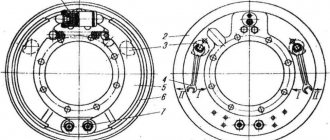
Brake system
► Malfunction: When you press the brake pedal, the car does not slow down - the brake warning light comes on
Probable cause: Worn friction linings, large gaps between the pads and drums of the service brakes
Remedy: Replace the friction linings. Adjust the gaps between the brake pads and drums
Probable cause: Lack of brake fluid in the master cylinder reservoirs
Remedy: Replace the brake fluid, bleed the brakes if necessary
► Malfunction: The minimum air pressure warning light is constantly on (with the engine running)
Probable cause: Lack of air in the cylinders due to a malfunction of the compressor, pressure regulator, or leaking pneumatic system
Elimination method: Eliminate the compressor malfunction, replace the pressure regulator. Locate the air leak and repair the damage
► Malfunction: Braking is not effective enough - the brake warning light comes on
Probable Cause: Brake fluid leak or air in the master cylinder or hydraulic line of one of the brake circuits
Remedy method: Determine the location of the fluid leak and repair the damage. Fill with brake fluid and bleed the brakes
► Malfunction: Braking is not effective enough - the minimum air pressure indicator light comes on
Probable Cause: Worn inner seal or lack of fluid in one of the master cylinders
Remedy: Replace the cuff. Add fluid, bleed the brakes
Probable cause: Worn piston cuffs or pneumatic booster spacer cuffs; in this case, when the pedal is pressed, air comes out of the air booster filter
Remedy: Replace the cuffs
► Malfunction: The brake jams (does not release)
Probable cause: Lack of brake pedal free play
Remedy: Adjust the brake pedal free play
Probable cause: Mineral oil entering the hydraulic drive, causing swelling of the rubber cuffs
Remedy: Wash the hydraulic drive with alcohol, replace the cuffs
Probable cause: Clogged compensation hole in the master cylinder
Remedy: Remove the tank and clean the compensation hole with a soft wire with a diameter of 0.6 mm
► Malfunction: Frequent operation of the pressure regulator
Probable cause: Compressed air leak in the line from the regulator to the valve block
Remedy: Tighten connections, replace faulty connection parts, pipelines
Relays and fuses
URAL relays and fuses are located in the cab on the mounting block to the right of the instrument panel under a removable cover. The serial number of fuses in the list corresponds to their numbering on the blocks.
1-relay for unloading terminal “15” (P2); 2-starter relay (P1); 3, 4, 6, 8, 9, 11 - fuse blocks; 5-relay for unloading terminal “15” (R3); 7-windshield wiper relay (R4); 10-rear fog lights relay; 12-diagnostic connector; 13-relay pneumatic brake signal switch (R12); 14-mirror heating relay (R11); 15-stop signal relay (R10); 16-horn relay (R9); 17-high beam relay (R8); 18-low beam relay (R7); 19-side light relay (R6); 20-relay additional rear fog lights (R5).
CAR ELECTRONICS REPAIR