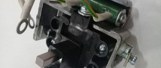
Ground button for Kamaz car
REMOTE MASS SWITCH
The mass on KAMAZ does not turn off.
Installing a mass switch on a car
Main switch, why it is needed, tips for choosing, installing a KAMAZ on a Mercedes.
Cabin structure of KamAZ 43114
KAMAZ instrument panel assembly
Everyday life of a KAMAZ driver – The charger has disappeared (replacing the voltage regulator)
KAMAZ 65221. Useful tips for novice drivers)))
Analysis of failures in the power supply system
The main causes of failures in the power supply system are:
– mechanical reasons (damage to live parts, their insulation and corrosion of contact surfaces, wear of mechanical parts);
– deviations of external conditions from normal (increased temperature, humidity or dustiness of the environment);
– exceeding the permissible electrical load in terms of voltage or current.
During vehicle operation, mechanical and electrical malfunctions occur in the power supply system, which cause disruption of the operation of electrical energy receivers of all other electrical equipment systems. Mechanical faults are determined by external inspection and noise during operation. Electrical faults are determined by readings from control devices.
During the operation of the vehicle, the following malfunctions of the power supply system occur.
All electrical energy receivers do not work
– the lighting system lamps do not light;
– the sound signal does not work;
– the starter does not turn on;
– the ammeter needle does not deviate towards the discharge when the devices are turned on.
Causes of the malfunction: the battery is faulty or completely discharged, the battery does not connect to the network
All receivers operate at low power when the engine is not running
– The starter does not rotate;
– lighting lamps burn with incomplete intensity;
– the sound signal sounds weak;
Disruption of the normal operation of all electrical energy receivers
– The battery is very discharged;
– increased resistance in the contact connections of the wire lugs at the battery terminals, the car frame, at the terminals of the battery switch, starter traction relay, ammeter;
– severe burning of the contact surfaces of the battery switch.
Battery won't charge
– while the engine is running at any crankshaft speed, the ammeter shows the discharge current.
– A break or low tension in the generator drive belt, an open circuit in the circuit connecting the generator and the battery (terminal “-1-” of the generator and the positive terminal of the battery);
– open circuit in the generator excitation circuit;
– short circuit to the housing of the generator excitation circuit, the generator is faulty;
– the voltage regulator is faulty.
Battery is not charging properly
– the ammeter shows the low charging current when the battery is discharged at any engine speed;
– when the headlights are turned on, the charging current sharply decreases or the ammeter shows a discharge current;
– sharp fluctuation of the ammeter needle.
– The voltage regulator is incorrectly adjusted;
– low tension of the drive belt;
– oiling or wear of the generator pulley;
– loose contact in the charging circuit or generator excitation circuit.
A large fluctuation of the ammeter needle is observed when the contact rings are oiled and the generator brushes are stuck, when, due to vibration of the car engine, the contact between the brushes and the rotor rings is periodically broken and restored, in the connections of loose wire tips in the generator excitation circuit and in the charging current circuit.
The battery is being recharged
– when the engine is running for a long time, the ammeter constantly shows the charging current, and its needle does not set to the zero scale division even with a fully charged battery;
– with an increase in the crankshaft rotation speed, a significant increase in the strength of the charging current occurs, which causes the needle to deviate beyond the limit value of the ammeter scale;
– strong gas formation in battery electrolyte;
– rapid decrease in the electrolyte level in batteries;
– increasing the brightness of lighting lamps at medium and high engine speeds;
– short service life of lighting lamps.
– malfunction or incorrect adjustment of the voltage regulator;
– short circuit between the wires connected to the terminals “-+-” and “Ш” of the generator.
In the event of a short circuit to the housing of terminal “Ш” of the generator or clamp Ш of the regulator, the voltage regulator will be switched off. As a result, the generator voltage with increasing rotation speed can reach an excessively high value that is dangerous for lamps and other receivers of electrical energy.
Vehicle power supply systems with alternating current generators and non-contact transistor voltage regulators (which is the system under consideration for KamAZ vehicles) are highly reliable in operation, subject to strict adherence to the rules of their operation. In particular, it is necessary to monitor the condition and fastening of the wires at the terminals of the generator, voltage regulator and battery. Operating the generator with the wire disconnected from the “-+-” terminal leads, with an increase in rotation speed, to an increase in the voltage on the rectifier unit, which in turn can lead to its failure and damage to the voltage regulator. An increase in generator voltage can also occur if the battery is disconnected by its switch while the generator is running.
The failure of the power transistor of the voltage regulator is caused by the short circuit of its terminals “-+-” and “Ш”. A particular danger to an alternating current generator set is connecting the battery in reverse polarity. This leads to failure of the rectifier block diodes.
Many drivers are interested in the question of why the electronics release gas on KamAZ-65115. The reason for this may be a malfunction of the engine, dead batteries, etc.
Malfunctions: causes and what to do
The main malfunctions that require KamAZ repairs are:
- Difficulty when changing gears; engaging reverse is accompanied by a grinding noise. To eliminate the breakdown, it is recommended to adjust the free play of the clutch and the clutch release mechanism.
- Extraneous noise in the divider housing. It can be caused by an increased level of pressure in the pneumatic control system of the device, wear of the cone-shaped rings that block the chamfers of the fingers and carriage. It is necessary to adjust the pressure reducing valve and replace the synchronizer.
- If spontaneous gear disengagement occurs while driving, you need to tighten the fastenings, conduct an external inspection of the clamps and, if necessary, replace worn mechanisms.
- If a leak appears in the transmission device, you should replace the seals, wash the breathers, replace worn gaskets and tighten the fasteners.
- If the gears in the divider stop engaging, it is necessary to adjust the valves and flush the throttle.
Error codes
Electronic control system - error codes for KamAZ with a Cummins engine (Euro-4):
| 111 | Unstable operation of the module that controls the power unit. |
| 143 | Reduced oil pressure level. |
| 146 | Increased coolant temperature. |
| 214 | Overheating of oil in the system. |
| 12 | Air temperature sensor malfunction. |
| SPN 132 FMI 3 | Too much fuel consumption when starting a vehicle. |
| 35 | Malfunctions in the cruise control system. |
| 23 | Incorrect position of the gas and brake pedals. |
| 27 | Failure of the steering rack. |
| 42 | The permissible engine idle speed has been exceeded. |
| 54 | High voltage level in the on-board network. |
| 55 | Unstable operation of the ECU control unit. |
| 43 | Speedometer malfunctions. |
| 28 | Brake system malfunction. |
| 18 | Incorrect operation of the camshaft. |
| 19 | Malfunctions in the main relay system. |
| 428 | Malfunctions in the fuel fluid sensor. |
| 595 | The number of turbocharging revolutions has been exceeded. |
| 281 | Incorrect position of the Bosch injection pump valves. |
| 422 | Insufficient amount of coolant. |
| 245 | Reduced pressure level in the fan control circuit. |
| 598 | Low voltage in the generator set circuit. |
| 1139 | Unstable operation of injector No. 1. |
| 441 | Low battery charge. |
| 442 | Recharging the battery. |
| 325 | Fuel consumption does not correspond to vehicle speed. |
| 434 | The network power has failed. |
| 2266 | Incorrect operation of the starting pump. |
| 687 | The number of turbocharger revolutions is reduced. |
| 126 | Working fluid temperature sensor error. |
Mileage 170 thousand km. Malfunctions and breakdowns during operation
Hello, I haven’t written anything new about the car for a long time.
I will write about the problems I encountered during this time: 1. It eats up the rubber on the outside of the front wheels on absolutely all cars. Every 30 thousand km I turn the tires over so that the wear is more or less even. By summer, with a mileage of approximately 250 thousand km, the cord will already be worn out, if you do not change 2. Grilles for fog lights are necessary. Those who are too lazy to install it drive with broken 3. They all have leaks from the steering tank. A friend wrote that it can be cured if you remove the lid, cut a washer from a plastic canister to the diameter of the tank, with a hole for a pin and a dipstick. I haven’t tried it myself yet 4. The wire on the corrugated gearshift lever frayed when switching the divider. The wire was cut and soldered. Everything worked 5 Gas equipment periodically fails. It gives an error and does not turn on. It is treated by bleeding the gas from the injector. We turn off the main gas supply valve at the rear of the cabin, raise the cabin, unscrew the engine mudguard on the left and bleed off the gas using a 5-point hex.
13. Below the fuse block there is a 24/12 converter. Don't ask him anything. This is a separate converter for gas equipment. For some reason, KAMAZ installed 12-volt gas equipment. For mass production, they could order 24-volt equipment. The standard converter is hidden somewhere under the sleeping bag in the autonomous area near the back wall under the plastic. I also didn’t understand why they put it there. 14. On two cars from our batch (30 pieces), the pump jammed. The thing turned out to be quite scarce. For example, they were transported to the Tyumen Kamaz Center from our service center in Nizhny. 15. The speed limiter in KAMAZ, as in other tractors, is set at 90 km/h from the factory, but for some reason, when accelerating downhill, the engine brake is activated already at 95 km/h. This is at least unsafe, because the road can be slippery. Without accelerating and braking the entire descent, you begin to stretch and accelerate into the climb, instead of flying halfway up the climb by inertia. This greatly affects consumption. To prevent it from turning on, the only option is to move the limiter, and this threatens trouble from management. 16. The filling valve of gas cylinders begins to turn sour and becomes more difficult to open and close. On several machines it is so tight that the valve handle has turned, and now the valve does not open, you need to install a new one. I tried to develop a VD with empty cylinders. It seems like I can turn easier. 17. I adjusted the ladder behind the cabin several times. When turning uphill, it gets hit by a trailer, moves from its place and is bent, after which it begins to dangle. So that at one moment it does not turn and wrap around the cardan, I removed it
Don’t be alarmed that I wrote so much, I think there are no absolutely reliable cars, even foreign cars. If you work on the car sometimes, and not just sit on your phone in the parking lot, then everything will be ok. Overall I like the car.
Source
Clutch adjustment
Adjusting the KamAZ clutch is carried out in several stages:
- Adjusting the free play of the clutch pedal. To do this, you need to measure the free play from the central part of the plate to the pedal itself. The gap should not exceed 12 mm. If the indicator is outside the normal range, you need to use an eccentric finger to press the pedal to the upper stop and turn the finger. Then you need to tighten the lock nut and measure the full stroke.
- Freewheel debugging. To do this, you need to move the fork shaft handle so that it moves in the direction of the spherical nut, which is located on the pneumatic power steering.
- Debugging the full stroke of the amplifier pusher. It is recommended to press the pedal all the way and measure the gap, which should be at least 2.5 cm. It is also necessary to measure the fuel fluid level in the cylinder block.
- Eliminate leaks in the system and adjust the clutch pedal sensor.
- Start the engine and check the operation of the coupling mechanism.
What you can do on your own
If this situation occurs, you need to make sure that the power supply is supplied to the truck cab at all. To do this, you need to sit in the cockpit and turn on the alarm button. The alarm is powered by other circuits and has a minimum of fuses for protection. If the emergency lights blink, then the KamAZ's power circuits are in order; it is necessary to check the main fuses and inspect the electrical wiring in the cab. If it doesn’t work, then the batteries may be faulty, there is no ground, or the external wiring is faulty. If you couldn’t do it on your own, our experts are ready to help.
A story from repair practice
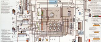
CAN A switching unit and electrical circuit components of KAMAZ 5490.
Diagram of the MR2 engine control unit and diagnostic systems.
ACR Electrical System Component Diagram - Neutralization Control Module.
Electronic circuit of the adaptation module for automotive functions of KAMAZ 5490:
How to change oil
The oil change should depend on the maintenance frequency. Before you start changing the oil fluid, you need to warm up the engine for 10-15 minutes. After this, you should wait until the power unit cools down. Before the procedure, you need to prepare a container to drain the old liquid.
To drain old oil, you must:
- Unscrew the plug on the crankcase body, which is located at the bottom of the sump.
- Drain the old fluid.
- Remove worn filters and install new filter elements.
- Close the pan plug.
- Pour new oil into the engine system.
- Conduct an external inspection of the mechanism for leaks.
- Warm up the engine to operating temperature.
When draining the old working fluid, it is recommended to inspect it for the presence of various impurities. This will help determine whether the engine needs to be flushed.
Kamaz power take-off
The power take-off with oil pump is designed to take power from the gearbox and is attached to its crankcase on the right side.
Gaskets are installed between the flanges of the power take-off housing and the gearbox, with the help of which the gear engagement of the gears is regulated. If gaskets are replaced, their overall thickness must be maintained.
Power take-off: 1 - plug, 2, 21 - gaskets, 3 - idler gear axis, 4, 16 - washer, 5, 23 - bearings, 6 - idler gear, 7 - thrust ring, 8 - lock washer, 9 - nut , 10, 12 — rings, 11 — compensator, 13 — set screw, 14 — power take-off housing, 15 — spring, 17 — pneumatic cylinder body, 18 — cuff, 19 — piston, 20 — pump NSh 32-L-2, 22 - coupling half, 24 - driven gear
In the crankcase 14, the driven gear 24 is located in ball bearings 23. On the axis 3, on the ball bearings 5, the intermediate gear 6 is secured with a nut 9 and a washer 8 with a bending antenna. axis 3, and then turn it back 1.5 turns and open it up. This allows the axis to move in the longitudinal direction.
The end of the axle with a piston 19 attached to it with a cuff 18 enters the body of the pneumatic cylinder 17. In the initial position, the axle is held by a spring 15. Oil leakage from the cavity of the box into the cavity of the pneumatic cylinder is prevented by a ring 12. To connect the driven gear 24 to the pump shaft, a half-coupling 22 is used, which through compensator 11 is connected to it. This connection prevents possible distortions of the rotation axis of the driven gear and the pump shaft when installing it on the power take-off.
In the initial position, the intermediate gear is in constant engagement with the gearbox gear. When compressed air is supplied to the pneumatic cylinder body, the intermediate gear moves to the left and its ring gear engages with the driven gear ring. The torque from the driven gear is transmitted to the pump shaft. The power take-off can only be turned on with a pressure of at least 500 kPa in the pneumatic system and with the clutch disengaged.
rice. 2
Power take-off drawing
KamAZ power take-off
If the gearbox is an obligatory part of the car chassis, and the presence of a transfer case and additional gearbox (multiplier or divider) depends on the purpose of the car, then the KamAZ power take-off takes practically no part in ensuring the movement of the car. The main task of this unit is to use engine power to operate additional equipment by transferring torque to the drive of this equipment. The principle of operation of the PTO is always the same, but the placement of the node may be different. So on KamAZ 4310 the power take-off is installed on the transfer case and consists of an output shaft, a pair of ball bearings in which it is fixed and a movable coupling. When the PTO is engaged, this clutch moves and engages with the upper shaft of the transfer case. The take-off box housing is sealed with rubber cuffs to prevent oil from leaking out through the bearing cup cover. A unit is used to transfer power to a standard winch.
In another version, the PTO is installed on the main gearbox. It is this type that includes, for example, the KamAZ 5511 power take-off, the crankcase of which is mounted on the right hatch of the gearbox (on some Kama trucks, a similar unit is installed on the left side, and very rarely on the rear end). The intermediate gear of the transfer case cannot move along the axis, so it constantly receives rotation from the intermediate shaft of the gearbox.
If it is necessary to turn on additional equipment, air is pumped into the chamber with the diaphragm, the diaphragm itself presses on the axis with the drive gear and it engages with the intermediate gear. It must be remembered that such a box only works when the clutch is disengaged and the pressure in the pneumatic system is at least 5 kgf/cm2. That is, switching the KamAZ gearbox when operating a PTO of this type is not recommended.
Due to the specific nature of the operation, the spare parts of this unit are exposed to increased external influences, so the strength and wear resistance of each PTO part are of great importance. In our company, you can easily buy a KamAZ power take-off of the type you need, and its price will be very reasonable. As for the quality and wear resistance of spare parts, all our products have successfully passed a full range of tests at MADI testing grounds and various technological checks. “Diagnosis” is the full approval of car manufacturers and consumers.
KAMAZ power take-off device
1 6511-4202005-20 Power take-off with pump assembly 2 1/34495/21 Stud M10x1.25x15x25 3 5511-4202018 Gasket 4 1/05168/70 Spring washer 10 5 1/21647/11 Nut M10x1.25 -6H 6 1/59707/21 Bolt M10x1.25-6gx25 7 864312 Plug M30x1.5-6g 8 870632 Sealing washer 30x42x2 9 5511-4202034-10 Idler gear axis 10 016-020-25-2-2 Ring 11 5511-4202040-10 Washer 12 (6-305) Bearing 12 864713 Bearing 6-305 13 5511-4202048-20 Set screw 14 5511-4202032-10 Intermediate gear 15 5511-4202016-10 Power take-off housing 16 862806 Ring B 62 G OST 5511.4202040 Lock washer 18 1/07269/11 Nut M24x1.5-6N 19 5511-4202091-10 Spring 20 1/05170/70 Spring washer 12 21 5511-4202068 Piston 22 100-3570228 O-ring 23 5511.42020 65 Pneumatic cylinder body 24 853965 Screw-in elbow 6 25 1/ 60436/21 Bolt М8-6gх25 26 1/05166/70 Spring washer 8 27 5511-4202200 (111) Bearing 28 5511-4202036-10 Driven gear 29 Ring 2B90 Ring 2B90 30 5511-4202064 Com pensator 31 5511-4202062-20 Half coupling 32 5511-4202081 Retaining ring 33 5511-8604087 Branch pipe 34 1/60436/21 Bolt М8-6gх25 35 1/05166/70 Spring washer 8 36 5511-8604087-10 Branch pipe (tropical version) 37 (G-5511-860 4000-10) Gear pump assembly 37 NSh32-L-2 Gear pump assembly 38 1/21647/11 Nut M10x1.25-6N 39 1/05168/70 Spring washer 10 40 Ring Ring 41 5511-8604088 Fitting 42 5511-8604157 Gasket 43 1 /13070/21 Bolt M10x1.25-6gx40 www.kspecmash.ru
The main reasons why the KAMAZ engine does not start:
- There is no fuel in the fuel tank;
- Presence of air in the fuel system;
- Clogged or contaminated fuel lines of the KAMAZ power supply system;
- The fuel has thickened due to low temperatures;
- Malfunctions of the high pressure fuel pump (injection pump malfunctions)
- Clogged fuel filters.
To determine the malfunction of the power system, you should follow the chain from less expensive and costly faults to more costly ones, taking into account the flow chart for repairing the power system.
Total information
The national economy of those years required a powerful and reliable dump truck, which determined the general characteristics of the vehicle.
In those years there was a nationwide construction boom, so the following was required:
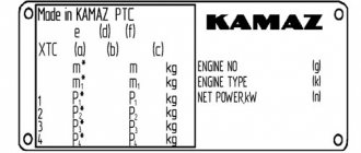
The sixth part - B1 The seventh part - B2 The eighth part - B3
And such a car appeared thanks to the focused and dedicated work of hundreds of automotive specialists. The ninth part – B4
Note! The best confirmation of the success of the design is the fact that the dump truck is still in use today.
Tenth part – B5
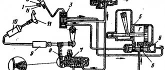
Platform control on KAMAZ-5511
To turn on the PTO on the KAMAZ5511 dump truck, you will need to move the lever on switch 6 to the “On” position; to do this, press the lock button, which is located on the body of this switch. In this case, the clutch must be disengaged. The signal lamp 5 will light up. And the electric current through fuse 8 will flow to the winding of the electromagnet on pneumatic valve 4.3, its core will move and open the valve. At the same time, air from the receiver will begin to flow into the cavity of the 3.3 KOM pneumatic chamber, and as soon as the clutch is engaged, pump 10 (oil) begins to work.
From oil tank 12, oil will flow through a pump through a pipeline into control valve 2 and then to drain back into the oil tank. Such oil circulation helps to warm it up in cold weather, which improves the operating conditions of the hydraulic system of the tipping mechanism.
Instructions on how to lift the body of a KamAZ 5511
To raise the 5511 dump truck platform, you need to press switch button 7 “Lift” to the “On” position. From the switch, the electric current will flow to the windings of electro-pneumatic valves number 4.1 and 4.2, their cores, having moved, open these valves. From the receiver, air is supplied to pneumatic chambers number 3.1 and 3.2 on the control valve. From the control valve, oil will flow through pipelines into hydraulic cylinder 1. Under the influence of oil pressure, all links of the hydraulic cylinder will sequentially extend, thereby lifting the platform. When the platform is raised, the hydraulic cylinder gradually tilts, and when the lift angle reaches 60°, the hydraulic cylinder body presses the adjusting screw in the platform lift limit valve (number 13 in the diagram below), the oil goes through the valve to drain. At the same time, the platform will stop rising.
Now you understand how to raise the body shock absorber; the cost of incorrectly adjusting the angle of inclination is, at a minimum, a breakdown of the hydraulic cylinder.
To stop the 5511 dump truck platform in its intermediate position, when lifting or lowering, it is necessary to move the “Lifting” or “Lowering” switch key to the “Off” position. At the same time, the electro-pneumatic valves are turned off, the air leaves the working cavities of the diaphragm chambers number 3.1 and 3.2. The hydraulic cylinder line closes, the cavity of the control valve begins to communicate with the drain line, and the oil goes to drain.
To lower the dump truck body, you need to move the switch key 7 to the “On” position. The current will flow to the winding of valve 4.1, its core, moving, will open the valve. The air will enter pneumatic chamber 3.1, in the control valve. From the hydraulic cylinder, the oil will flow through the tap into the tank. After the platform is completely lowered, you should move the key on switch 7 to the “Off” position. The lever on switch 6 is also set in the neutral position, while at the same time depressing the clutch pedal. The oil pump will stop working. It should be noted that the KAMAZ-5511 body can be lowered both when the oil pump is running and when the pump is already turned off.