working equipment, technical characteristics, modifications
To carry out various excavation works it is necessary to have specialized equipment. This includes the Soviet-made legend - the EO 4321 excavator.
Features of the EO 4321 excavator
This model was first manufactured back in 1972 at the Kiev Machine-Building Plant. EO 4321 had all the necessary parameters and mechanisms for carrying out work in the field of agriculture, construction of buildings and transport facilities. This model belongs to the fourth group of specialized equipment.
A distinctive feature of the EO 4321 wheeled excavator model is that this excavator was the first pneumatic wheeled machine with a hydraulic boom. It was he who became the founder of subsequent modifications. The unique combination of efficiency and cost-effectiveness in use contributed to the spread of EO 4321 throughout the union.
This excavator was in service with the engineering troops and worked on almost all construction sites.
The positive qualities of the model include:
- Large bucket capacity;
- Availability of own supporting parts with hydraulic drive;
- Increased productivity by replacing a mechanical drive with a hydraulic one;
- Using an excavator blade to improve stability;
- Easy access to all elements of the engine and attachments reduces the cost of maintenance personnel and reduces repair time.
Photo of excavator EO 4321
Also, the advantages of the EO 4321 excavator include its versatility. Depending on the work performed, it is possible to attach various equipment to the hydraulic boom. Possibilities include excavation and trenching, well digging, site leveling, and hard rock loosening and crushing.
Working equipment
The main working part of an excavator is a backhoe, the capacity of which is 0.65 m3. If necessary, you can change the equipment to a straight shovel to develop soil above the level of the machine. For the construction of deep pits and wells, it is possible to install a grab handle on the handle. For loading bulk materials, a backhoe or straight shovel bucket is used, and for piece cargo, a special crane installation is used.
The rotating platform is located on a pneumatic wheel chassis. This is where the power equipment, driver's cabin, tanks for working fluid and fuel, counterweight, hydraulic mechanism and its control system are located.
Design of the EO 4321 excavator
The running structure consists of a durable frame and pneumatic wheels. The frame is equipped with special supports and bulldozer-type equipment. Control is carried out by turning the front axle.
Specifications
All technical characteristics of the EO 4321 excavator are presented in tabular form.
| Characteristics | Options |
| Engine power, kW | 59 |
| Excavator operating weight, kg | 19, 8 |
| Backhoe/forward shovel capacity, m | 30,5/0,8 |
| Maximum digging depth, m | 5,5 |
| Backhoe loading height, m | 5,6 |
| Digging height with straight shovel, m | 7,9 |
| Maximum height of material unloading (straight shovel), m | 5,67 |
| Travel speed, km/h | 20 |
| Excavator dimensions (LxWxH), m | 9.9x2.84x3.99 |
Main modifications
During the entire production of excavators of this series, many changes were made in the power equipment and hydraulic system.
Every year the model has been modernized and improved to achieve maximum efficiency and performance.
There are several modifications of EO 4321, which include the following:
- Eo 4321A. Conveyor production began in 1983. Changes were made to the hydraulic system, and a new arm and boom were installed. The unique qualities of the excavator contributed to its being awarded the gold medal of the VDNH of the Soviet Union;
- Eo 4321B. The first excavator of this model was released in 1987. The developers were able to increase the productivity of the equipment by 16% compared to the previous modification;
- Eo 4322. This model became the next stage in the development of construction equipment. It was produced since 1989 and had a limited number of copies. The appearance of the model completely copied the EO 4321, but the power equipment and hydraulics were radically changed. Improved components of the main equipment have allowed hydraulic excavators to move to a new technological level.
magistraltrade.ru
Design, technical characteristics and operation of excavators
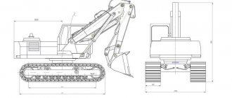
A single-bucket excavator (Fig. 6.2) in most cases consists of a fixed 1
and a rotating part
2
, connected to each other by a rotating support device
3
.
The fixed part with the movement mechanisms or the base vehicle is the supporting base of the excavators. A rotating platform rests on it through a rotating support, the rotation of which is carried out by a rotating mechanism.
The rotating part consists of a rotating platform with mechanisms and power equipment and working equipment.
Rice. 6.2. Single bucket construction excavator:
1
– fixed part;
2
– rotating part;
3
– rotating support;
4
– boom;
5, 8, 9
– hydraulic cylinders;
6
– ladle;
7
– handle;
10
– cabin
The rotating platform is made in the form of a frame. It is equipped with working equipment and a drive, which, with the help of a power plant and transmission, drives the working equipment, and in some cases, the running gear. In the front part of the turntable frame there is a cabin 10
with machine controls.
In addition, the turning mechanism and elements of hydraulic and electrical equipment are located on the rotating platform.
The turntable rests through a special roller slewing device on the frame of the running device and can be rotated relative to it in a horizontal plane. The same turntable can be installed on different types of undercarriages.
The power plant, consisting of a diesel engine and a pumping unit driven by it, is usually located in the rear part of the turntable. The supply of working fluid to the hydraulic motors and brakes of the travel mechanisms and/or hydraulic supports is carried out through the central manifold.
The mechanisms and units located on the turntable are covered with hoods. Ahead of the platform, the boom and hydraulic cylinders of the boom of the working equipment are installed in the eyes of the brackets. A counterweight is attached to the rear to balance the excavator.
The working equipment includes a set of elements consisting of a working body 6
(bucket, grab, hook, etc.) and devices that ensure the movement of the working body in the excavator work area (boom
4
; handle
7
; hydraulic cylinders
5, 8, 9
or ropes for excavators with flexible suspension of working equipment).
The working equipment of single-bucket excavators allows you to perform a number of different works, including those not directly related to excavation work (pile driving, lifting and loading equipment, uprooters, etc.).
Modern construction excavators can be equipped with working equipment and working bodies of up to 35 types.
The road troops use excavators with working equipment: a straight shovel, a backhoe, a loader, and a grab. Excavators with working equipment can be used as additional earth-moving machines: dragline, hydraulic hammer, ripper, etc.
The “backhoe” working equipment is designed to develop soil below the excavator parking level (trenches, pits, etc.) with unloading the soil into a dump or vehicles. Its main components are the boom, handle, bucket and hydraulic cylinders for lifting the boom, turning the handle and turning the bucket.
The “straight shovel” working equipment is intended for developing soils above the excavator parking level (quarries, excavations, etc.) with loading the soil into a vehicle. A “straight shovel” with a rotating bucket can level the face. The main components of the “straight shovel” are the base part of the boom, a special handle, a bucket with a lever and rod, hydraulic cylinders for lifting the boom, turning the handle and turning the bucket.
The “loader” working equipment is designed for excavating soil and loading bulk crushed materials above the machine parking level. The productivity of an excavator with “loader” equipment is higher than that of a “straight shovel”, since the loading bucket has a capacity 1.5-2 times greater. The kinematic diagram of the loading equipment (articulated quadrangle-parallelogram) ensures the movement of the cutting edge of the bucket along a straight horizontal path at the machine parking level over a considerable length, which allows for leveling work. The main elements of loading equipment are the boom, handle, rods, bucket suspension, bucket, boom hydraulic cylinders, the rods of which are attached to the handle brackets, hydraulic cylinder of the handle and hydraulic cylinder of the bucket, mounted with trunnions in the bucket suspension.
The “grab” working equipment is designed for digging wells, trenches, loading and unloading bulk materials. The grab equipment is mounted on the handle of the backhoe instead of the bucket. The rigid suspension of the grab provides the ability to develop dense soils. The grab equipment consists of two jaws, which are hinged to the frame. The teeth and cutting edge of the bucket are coated with hard alloy. The jaws are connected to the slider by rods. The opening of the jaws is carried out by a hydraulic cylinder, which is installed between the longitudinal beams and is connected by an eye to the frame, and by the eye of the rod to the slider.
The road troops are armed with a military hydraulic single-bucket excavator (Fig. 6.3) EOV-4421. It is intended for the mechanization of excavation and loading and unloading operations when equipping troop positions and command posts.
Rice. 6.3. General view of the EOV-4421 excavator
It consists of a base vehicle - a KrAZ-255B all-terrain vehicle, excavator equipment placed on a turntable, and a strapping frame with four outrigger hydraulic supports. The main parts of excavator equipment are the power unit, working equipment, hydraulic drive and electrical equipment.
The power plant is located on the rotary platform of the excavator. It consists of a four-stroke four-cylinder diesel engine SMD-14 with a power of 75 hp. liquid cooling with a vortex combustion chamber and its servicing systems: fuel supply, air supply, lubrication, cooling and starting.
The fuel supply system consists of a fuel pump with an all-mode centrifugal-type regulator, a booster pump with a fuel booster pump, pin injectors, closed-type coarse and fine filters for the fuel tank, and control devices.
The air supply system is designed to clean air from dust, supply it to the cylinder and includes an air cleaner and an intake manifold.
The diesel lubrication system is combined, consisting of a gear, single-section oil pump, centrifuge, oil cooler, control devices and pipelines.
The diesel cooling system has a closed liquid circulation and includes a centrifugal water pump with a fan and radiator, a thermostat and instrumentation.
To start the diesel engine there is a single-cylinder carburetor two-stroke starting engine PD-10U with a gearbox SMD8-19S4V. The PD-10U engine is started using an ST-350 electric starter. To facilitate diesel starting at low ambient temperatures, an electric torch pre-heater is provided.
A detailed description of the structure of the SMD-14 engine, as well as instructions for its operation and adjustments, are given in the technical description and operating instructions “Diesel SMD-14 and its modifications”.
The working equipment of the excavator consists of the main (backhoe) and additional equipment.
The backhoe (Fig. 6.4) is designed to develop soil below the excavator parking level and consists of a unified boom 1
, handle
6
, bucket
7
, hydraulic cylinders
2, 4, 5
, pipelines and high-pressure hoses
3
for supplying working fluid to the hydraulic cylinders.
As additional equipment for loading and unloading operations, a hook suspension is installed on the bucket handle.
The boom, arm and bucket are hingedly connected to each other using pins and bronze bushings, which are plain bearings. Raising and lowering the boom is carried out by two hydraulic cylinders 2
.
The handle is rotated in a vertical plane by hydraulic cylinder 4
, and the bucket is rotated by hydraulic cylinder
5
.
To lubricate the rubbing surfaces of the hinge joints, all pins and bushings of the excavator working equipment have oil nipples through which lubricant is supplied to the rubbing surfaces.
The boom (Fig. 6.5) is designed to install a handle with a bucket and hydraulic cylinders on it. It is a one-piece welded structure with an L-shaped box section.
Rice. 6.5. Arrow:
1
- boom base bushing;
2
- technological hole;
3
— holes for fastening the boom hydraulic cylinder rods;
4
— eyes for attaching the hydraulic cylinder of the handle;
5
— bushings for installing the handle;
b
- handle lugs
The welding points of the boom components are reinforced with welded plates and overlays. With its base the arrow using a pin installed in the sleeve 1
, is pivotally connected to the brackets of the excavator turntable.
There are two holes in the middle part of the boom 2
and
3
, the first of which is used to connect the hydraulic cylinder rods of the boom with a pin to the eyes, and the second is not used in the EOV-4421 excavator: its presence is due to the unification of the metal structure of the boom with the boom of the E-5015A excavator.
At the top of the boom, where it bends, lugs are welded 4
to secure the hydraulic cylinder of the handle drive in them.
At the end of the boom there are two eyes 6
, into the holes of which bushings
5
for hinge connection using a pin with a handle.
The handle (Fig. 6.6) is an elongated welded box-section structure made of rolled sheets. In the middle part of the handle there is a hole with a sleeve pressed into it 7
, which, together with the finger, provides a hinged connection between the handle and the excavator boom.
rod of the handle drive is hingedly attached to the eyes of the upper end of the handle using pin 1
.
Rice. 6.6. Handle:
1
— pin securing the hydraulic cylinder rod to the handle;
2
— bracket for installing the bucket hydraulic cylinder;
3
- thrust;
4
— bucket mounting bushings;
5
— hook suspension bracket;
6
— bracket for securing the hook in the non-working position;
7
— bushing for installing the handle on the boom
Brackets are welded on the front side of the handle 2
for hinged mounting of the bucket hydraulic cylinder in them.
Rods 3
.
Using pins and bushings 4,
the bucket is hinged to the handle.
Brackets 5
for the hook suspension and brackets
6
for securing the hook in the non-working position are welded to the bottom of the handle.
The ladle (Fig. 6.7) is a welded volumetric structure made of rolled sheets.
To articulate the bucket with the handle to the top sheet 6
two eyes
2
, each having two holes with bushings
3
and
5
;
With the help of a pin and bushing 3
, the bucket is pivotally attached to the handle, and with the help of a pin and bushing
5
- to the rod.
To protect against falling out and turning, the fingers have locks 4
.
Side walls 7
,
8
and the bottom
9
of the ladle, forming its container, are welded together and welded to the top sheet.
In the front part of the bucket there is a cutting contour consisting of side knives 1
and a visor
10
, to which brackets
12
for installing four replaceable teeth
13
.
The teeth are kept from falling out by cotter pins 11
.
hook suspension (Fig. 6.8) is additional equipment and is designed to perform lifting operations with loads weighing no more than 3 tons.
The hook hanger consists of a hook 8
with a safety lock
9
, a hook axis
6
, an eye
4
and a bracket
2
welded to the handle
3
.
Bracket 2
in the lower part has holes for pin
1
, which pivotally connects the bracket with eye
4
.
Rice. 6.7. Ladle:
1
- side knife;
2
- eye;
3
and
5
— bushings;
4
— clamps;
6
- top sheet;
7
- right wall;
8
— left wall;
9
— bottom;
10
- visor;
11
— cotter pin;
12
— bracket;
13
– tooth
To the bottom of the eye using an axle 6
the hook is attached.
The eye consists of two detachable plates, the upper parts of which are curved and form half-length bushings, connected to each other by pin 1
.
The design of the eye allows the lower parts of the plates to be moved apart from each other relative to the pin axis until they stop due to the gaps between the upper parts of the eye plates, which ensures that the hook axis 6
.
The hook axis in its middle widened part has a recess for installing the lower ring of the thrust ball bearing and a hole for the hook shank, and its ends have threads for screwing on nuts 7
, holding the hook axis from longitudinal displacement.
The hook with its shank is installed in the hole of the axle. A thrust ball bearing with a clamping cup is pressed onto the cylindrical part of the hook shank, and a clamping nut is screwed onto the threaded part 5
. The nut is secured with a pin from turning.
Tightening the nuts should ensure free rotation of the thrust bearing and rotation of the hook axis.
Fixation of the hook suspension in the non-working position is carried out using a finger 10
, installed in the hole of the bracket
11
. The finger has a built-in hinge pin that prevents it from falling out.
Rice. 6.8. Hook suspension:
1
- finger;
2
— bracket;
3
— handle;
4
- eye;
5
— clamping nut of the hook shank;
6
— hook axis;
7
— axle fastening nut;
8 - hook; 9
— safety lock;
10
- finger;
11
— bracket for fixing the hook in the non-working position
The hydraulic drive of the excavator is designed to perform the following operations: transfer of working equipment from the transport position to the working position and back; implementation of all working movements of working equipment when excavating pits, trenches (cracks) and when performing lifting operations; raising and lowering outriggers.
All operations are controlled from the excavator operator’s cab. The excavator is equipped with a volumetric hydraulic drive, the schematic diagram of which is shown in Fig. 6.9.
The main elements of the hydraulic drive are: two-section axial piston pump of adjustable capacity 20
;
hydraulic distribution equipment with a system of 21
and
4
valves;
actuating units, including a high-torque hydraulic motor 3
for turning the platform, hydraulic cylinders for working equipment
5, 6, 7
and outriggers
8, 11
;
hydraulic filters 17
mounted in the working fluid tank
18
; connecting equipment consisting of pipelines, high-pressure hoses, rotary joints and other auxiliary elements.
The hydraulic drive of the excavator ensures the combination of the working operations of the boom, arm and bucket with the rotation of the platform, which helps to increase the productivity of the excavator.
The hydraulic drive diagram determines the fundamental relationship between its elements: pumping unit, control and distribution devices, hydraulic motors and other equipment, regardless of their design.
Rice. 6.9. Schematic diagram of the hydraulic drive:
1, 13, 14
— hydraulic distribution blocks BR18, BR16 and BR17;
2
- check valves;
3
— hydraulic motor for turning the platform;
4
— bypass valves (valve block);
5, 6, 7
— hydraulic cylinders of working equipment;
8
and
11
— hydraulic cylinders of outriggers;
9
and
10
- shut-off valves;
12
- central manifold;
15
— three-way valve;
16
— heater;
17
— hydraulic filters;
18
— working fluid tank;
19
— SMD-14 engine;
20
- hydraulic pump;
21
- safety valve;
22
— pressure gauge;
23
- unloading valve
In terms of the number of flows of working fluid supplied from the pump, the hydraulic drive circuit of the excavator is two-flow with the ability to combine (separate) the flows manually and separate-sequential power supply to the hydraulic motors.
Hydraulic pump drive 20
is carried out from the diesel engine
19
SMD-14 (SMD-14-NG).
The flow of working fluid from the right and left sections of the pump enters monoblock hydraulic valves 1, 13
and
14
.
In this case, the flow from the right section goes to hydraulic valve 1
, and from the left section to hydraulic valves
13
and
14
.
If the spool valves in hydraulic valve 1
are in the neutral position, then the working fluid passes through its central channel, like through a pipeline, and connects at point “B” with the flow of working fluid coming from the left section of the pump.
The total flow of working fluid from two sections of the pump (with neutral position of the spools in the hydraulic valves 13
and
14
), passing through their central channels, enters the three-way valve
15
.
Depending on the position of the three-way valve 15
the flow of working fluid can be directed to the oil cooler (heater)
16
and then through filters
17
to the oil tank
18
or, bypassing the oil cooler, sent directly through filters
17
to the tank.
The hydraulic valve spools 1
control the hydraulic motor
3
for turning the platform, the hydraulic cylinder
5
of the bucket handle and the hydraulic cylinders
8
of the left outriggers.
Hydraulic valve spools 14
control hydraulic cylinders
6
of the boom, hydraulic cylinder
7
of the bucket and hydraulic cylinders
11
of the right outriggers.
One of the distributor spools 13
is interlocked with the distributor spool
14
and moves with it synchronously from one lever when controlling the hydraulic cylinder
5
of the bucket handle.
The second distributor spool 13
is reserve and can be used to control the executive bodies of replaceable attachments.
Thus, the executive bodies controlled by the hydraulic distribution block 1
, are powered only from one section of the pump, and the actuators, controlled by hydraulic distribution blocks
13
and
14
, when the spools of hydraulic distribution block
1
, are supplied from two sections of the pump.
The excavator hydraulic system allows you to combine one working movement controlled by a hydraulic distribution block 1
, with one working movement controlled by distribution blocks
13
and
14
.
In addition, the spool for controlling the operation of the boom hydraulic cylinders 6
is designed in such a way that it allows the operation of the boom hydraulic cylinders to be combined with one of the working movements controlled by four spools of the hydraulic distribution blocks
13
and
14
. Consequently, three working movements can be combined simultaneously.
When combining operations, each of the hydraulic cylinders is fed by a flow of working fluid from one section of the pump. Hydraulic cylinder only 5
The bucket handle, when combined with the operation of the boom hydraulic cylinders, receives a double flow of fluid due to the fact that it is controlled using interlocked distributor spools operating synchronously.
To protect the hydraulic system from overloads to the pressure lines of each pump section 20
safety valves
21
.
The pressure in the working cavities of the hydraulic motor 3
of the platform turning mechanism is limited by safety valves located in block 4, and the cavities of the hydraulic motor
3
2
in order to prevent vacuum in them .
To prevent an excessive increase in jet pressure in the hydraulic cylinders of working equipment in the cavities of hydraulic distribution blocks 1
and
14
unloading valves
23
.
In order to prevent leakage of working fluid from the piston cavities of one outrigger hydraulic cylinder to another, shut-off valves are installed 9
And
10
.
The flow of working fluid from the rotating platform to the fixed part of the excavator is supplied through the central manifold 12
.
MG-30 oil is used as a working fluid in the hydraulic drive of an excavator at positive temperatures.
The work of the excavator hydraulic drive is reduced to performing certain operations of rotating the platform, operating the hydraulic cylinders of the working equipment and raising and lowering the outriggers.
The platform is rotated using the spool “P” of the BR18 distribution block (Fig. 6.10). When moving the spool “P” from the neutral position into the working flow of the working fluid from the right section “A” of the hydraulic pump 15
through the channels in the hydraulic distribution block BR18 enters under pressure into the pressure line of the hydraulic motor
8
and causes it to rotate.
From the hydraulic motor drain line, the flow of working fluid flows to the drain into the common drain line. During active rotation of the platform, i.e. during the flow of working fluid into the pressure line, the bypass valve 9
and the block of make-up valves
7
do not work.
When the spool “P”, which controls the rotation of the platform, returns to the neutral position, the pressure and drain lines of the hydraulic motor are locked by the spool.
The turntable, turning by inertia, carries the hydraulic motor along with it 8
, which in this case operates in pump mode.
The flow of working fluid created by the hydraulic motor opens one of the bypass valves 9
and is directed to the opposite line of the hydraulic motor under a valve setting pressure of 170±5 kgf/cm2.
In this case, the hydraulic line that powers the hydraulic motor operating in pump mode is replenished with working fluid from the drain hydraulic line through the corresponding check valve. 7
.
Rice. 6.10. Hydraulic drive operating diagram:
1
— shut-off valves:
2, 3
— hydraulic cylinders of outriggers;
4
— boom hydraulic cylinders;
5
— hydraulic cylinder of the handle;
6
— bucket hydraulic cylinder;
7
- check valve;
8
— rotation hydraulic motor;
9
- bypass valve;
10
— hydraulic distribution block BR18;
11
— hydraulic distribution block BR17;
12
— hydraulic tank;
13
,
18
— unloading valves;
14, 17
- safety valves;
15
- hydraulic pump;
16
— power regulator;
19
— hydraulic distribution block BR16;
20
— central collector;
21
— damper valve
Replenishment with working fluid is necessary to compensate for leaks of working fluid from the system and to prevent the occurrence of vacuum in the hydraulic line and cavities of the hydraulic motor.
To drive the hydraulic motor of the platform rotation mechanism, only one section of the hydraulic pump is used. Therefore, the rotation of the platform can be combined with any movement of the working equipment.
The operation of the hydraulic cylinders of the working equipment (Fig. 6.10) is carried out using spool valves located in the hydraulic distribution blocks BR16 (control of the boom and bucket hydraulic cylinders), BR17 and BR18 (control of the hydraulic cylinder of the bucket handle).
When moving one of the spools “C” and “K” of the BR16 distribution block or the spool “P” of the BR17 block from the neutral position into the working flow of the working fluid from two sections “A” and “B” of the hydraulic pump 15
under pressure it enters through the check valves of the hydraulic distributors and the corresponding pipelines into the rod or piston cavities of the hydraulic cylinders
4
of the boom, the hydraulic cylinder
6
of the bucket or the hydraulic cylinder
5
of the handle.
The movement of the rods of these hydraulic cylinders causes the movement of the boom, arm or bucket.
The hydraulic circuit ensures independent combination of hydraulic cylinder movement 5
handles with the movement of hydraulic cylinder
6
of the bucket or hydraulic cylinders
4
of the boom.
Due to the design of the hollow spool “C”, which controls the hydraulic cylinders 4
of the boom, it is possible to sequentially combine the movements of the hydraulic cylinders
4
of the boom and the hydraulic cylinder
6
of the bucket.
During excavation work, large reactive pressures arise in the locked cavities of the hydraulic cylinders. To limit these pressures, unloading valves are built into the corresponding cavities of the hydraulic valves 13
and
18
.
When the reactive pressure in the cavities of the hydraulic cylinders increases above the permissible value (valve setting pressure), valves 13
and
18
connect these cavities to the drain line.
To ensure smooth lowering of the boom, a check damper valve is installed in spool “C”, which controls the movement of the boom hydraulic cylinders. 21
.
Thus, the hydraulic circuit allows efficient use of the full power of two pump sections 15
, if necessary, directing the total flow of working fluid to one of the cylinders of the working equipment or distributing it to several hydraulic cylinders simultaneously. This ensures the combination of all necessary movements of the working equipment.
Raising and lowering of outriggers is carried out by spool valves “Op” and “Ol” located in the distribution blocks BR16 and BR18. When the “Op” spool is turned on in the operating position, the flow of working fluid is directed from the BR16 distributor through pipelines through the central manifold 20
and shut-off valves
1
to the hydraulic cylinders
2
right (along the machine) outriggers.
When the “Ol” spool of the BR18 distribution block is turned on, the flow of working fluid in the same sequence flows to the hydraulic cylinders 3
left outriggers.
Shut-off valves 1
prevent the flow of working fluid from the piston cavity of one cylinder to another. In addition, the shut-off valves close the reactive pressures from the outriggers, thereby protecting the rotating elements of the central manifold from excess pressure. This increases the reliability and durability of the central manifold.
The electrical equipment of the EOV-4421 excavator is the electrical equipment of the base vehicle with a voltage of 24 V and the excavator electrical equipment with a voltage of 12 V.
A description of the electrical equipment of the base vehicle is given in the operating instructions for the KrAZ-255B vehicle and is not discussed in this chapter.
The electrical circuit diagram of excavator electrical equipment is shown in Fig. 6.11.
Excavator electrical equipment is located on the rotating platform of the excavator and consists of sources and consumers of electrical energy, auxiliary equipment, instrumentation, and electrical wires.
The sources of electrical energy are the battery 24
and a generator
20
, working in conjunction with a relay regulator
19
.
Consumers of electrical energy include an electric starter 25
, electric lamps
1, 4, 9, 13, 15, 26
, electric motors of fan
2
and windshield wiper
7
, sound signal
27
.
Instruments include an ammeter 22
, the temperature indicator of the working fluid
6
of the hydraulic system and the water temperature indicator
8
in the engine cooling system, which are located on the instrument panel in the excavator driver’s cab.
All sources and consumers of electrical energy are connected via a single-wire circuit. The negative terminal of the battery is connected to the “body” of the excavator equipment.
In addition to the EOV-4421, the road troops use the EO-2621 excavator (Fig. 6.12) and the EO-3322A excavator.
The excavator is designed for excavating category 1-3 soils and loading bulk and finely crushed materials. The machine has two types of working equipment: excavator and bulldozer.
Excavator equipment is the main working body and is a unified bucket of forward and backward shovels with a capacity of 0.25 m3. In addition, the excavator can be equipped upon special order with a loading bucket with a capacity of 0.5 m3, a crane suspension, forks, grab equipment and a backhoe with an offset digging axis.
Rice. 6.11. Electrical diagram:
1
— headlight FG-304;
2
— cabin fan;
3
— switch VK-26-A2;
4
— lamp PK201A;
5
— switch VK-26-A2;
6
— oil temperature indicator UK 133M;
7
— windshield wiper SL 123;
8
— water temperature indicator UK 133-V;
9
— control lamp PD-20-E;
10
— sensor TM 103;
11
— water temperature indicator sensor TM 100;
12
— oil temperature indicator sensor TM 100;
13
— portable lamp PLTM-3.5;
14
— 47K socket;
15
— engine compartment lamp PD-308;
16
— heater;
17
— control element PD50V;
18
— switch VK 317-A2;
19
— relay-regulator PP362-B;
20
— generator G306G;
21
— fuse PR12-D;
22
— ammeter AP-200;
23
— switch VK 318-B;
24
— battery STST EMC;
25
— ST350 starter;
26
— instrument panel lighting lamp A12-21;
27
- signal C302;
28
- SZZ signal
;
29 — switch PZOO-B;
30
— RSZZ relay;
31
— switch VK 322;
32
— connecting panel PS2-A2;
33
— vehicle power supply;
34
— switch VK-26-A2;
35
— headlight FG318
Bulldozer equipment is installed in front of the tractor and is used for filling trenches, clearing roads of snow, and raking construction waste. It can be used to work with soils up to category 2 inclusive.
Rice. 6.12. General view of the EO-2621 excavator
The working equipment is mounted on frames, the fastening of which is made in such a way as to relieve the load on the tractor frame.
Using a hydraulic cylinder, the blade can be installed at different heights. In addition to its main purpose, the blade also serves as a counterweight. To increase the stability of the excavator, outriggers are used, which are attached to the frame. Using two hydraulic cylinders, the supports can be lowered to the ground or raised up while the machine is moving.
The frame also houses the excavator's hydraulic system, a rotation mechanism and excavator working equipment, consisting of a boom, a handle and a bucket. Each of these units is controlled using one (boom and bucket) or two hydraulic cylinders (arm). Liquid is supplied to the hydraulic cylinders under pressure from the pumping unit. The supply of working fluid for hydraulic cylinders is in the tank.
The machine is controlled by moving the hydraulic valve spools. The driver's seat can be rotated 180 degrees.
In one position, the driver controls the tractor during its movement, and in the other, the operation of the excavator. For ease of maintenance, the fuel tank is located in the front part of the tractor.
The operator can replace the working equipment within an hour using a crane with a lifting capacity of at least 0.25 tons. In the absence of lifting equipment, the participation of a second worker is necessary for reinstallation.
The excavator operates two hydraulic systems: one of them is installed on the tractor; the other is for driving working equipment units - on an excavator.
The tractor's hydraulic system includes a gear pump of the NSh-67K type, which is driven from the diesel shaft through a gearbox. The pump supplies fluid through a hydraulic distributor to the boom hydraulic cylinder and to the hydraulic cylinder of the turning mechanism, as well as through the tractor hydraulic distributor to the hydraulic cylinders of the outriggers and the hydraulic cylinder of the bulldozer.
The excavator hydraulic system (Fig. 6.13) includes two gear pumps of the NSh-32U type, which supply fluid to the hydraulic cylinders through a hydraulic distributor. The boom hydraulic cylinder is powered either from each hydraulic system separately, or from two hydraulic systems with the total flow of working fluid in order to speed up the work operation.
Rice. 6.13. Hydraulic diagram of the EO-2621V excavator on the YuMZ-6A tractor:
1
— hydraulic tank;
2, 3
— gear pumps;
valves: 4
- unloading,
9
— reverse,
12
— bypass;
hydraulic cylinders: 5
- booms,
6
- handles,
7
- bucket,
11
- turning,
13, 15
- outriggers,
14
- bulldozer;
8
— throttle;
10
— rotation mechanism;
I - III
- hydraulic valves
To protect the excavator mechanisms from overloads, valves are installed in the hydraulic distributors. A relief valve is connected to the boom hydraulic cylinder pipelines to protect the hydraulic cylinder rod from bending when reaction pressures occur. If the pressure in the locked piston cavity of the hydraulic cylinder increases excessively, the unloading valve releases liquid into the rod cavity of the hydraulic cylinder, and excess liquid into the tank.
The turning mechanism consists of a turning column, a chain transmission and two hydraulic cylinders. The rotary housing rests on tapered roller bearings and rotates relative to the frame head cup using a chain sprocket driven by a chain from hydraulic cylinders. Both hydraulic cylinders work alternately. If the rod of one hydraulic cylinder is retracted, then the chain connected to it by a rod rotates the sprocket and housing, while the other hydraulic cylinder idles.
In order to increase the torque developed by the turning mechanism, the working fluid is supplied under pressure into the piston cavities of the hydraulic cylinders.
The rod cavities of hydraulic cylinders are also filled with liquid and connected to each other. If liquid is supplied to the piston cavity of one of the hydraulic cylinders, then pressure also arises in its rod cavity, which is transferred to the rod cavity of the other turning hydraulic cylinder. The chain sprocket will begin to rotate together with the rotary column body and the working equipment attached to it. Fluid losses in the rod cavities are compensated through a check valve connected to the handle pipelines. Smooth automatic braking of the turning mechanism in the middle of the stroke is carried out using a bypass valve, and at the end of the stroke - due to damping devices mounted in the rear covers of the hydraulic cylinders.
The body has eyes for installing the boom and its hydraulic cylinder, as well as a boss with a pin for fixing the rotation mechanism in the transport position.