The engine mechanisms and systems, as well as their main indicators, include the following.
The crank mechanism serves to convert the reciprocating motion of the piston (pistons) into rotation of the crankshaft. In addition, it is involved in the conversion of thermal energy into mechanical energy.
The action of the mechanism is that the piston, performing a reciprocating movement through the connecting rod, rotates the crankshaft 1 in the bearings.
During reciprocating motion, the pistons occupy different positions, at which the volume of the cylinder changes.
Top dead center (TDC) is the position of the piston in the cylinder at which the distance from the bottom of the piston to the axis of the crankshaft is greatest.
Bottom dead center (BDC) is the position of the piston in the cylinder at which the distance from the bottom of the piston to the axis of the crankshaft is the smallest.
The stroke of the piston S is equal to its movement between dead points.
The working volume of the cylinder Vh is equal to the volume released by the piston when moving from c. m.t.k.n. m.t.
Compression chamber volume Vc is the volume formed above the piston when it is in. m.t.
Rice. 1. Main parts of an internal combustion engine: 1 - crank mechanism; 2 — gas distribution mechanism; 3— power supply system; 4 — cooling system; 5 — crankcase ventilation; 6 — balancing mechanism; 7 - lubrication system; 8 — starting system; 9 - pallet; 10 — cylinder block; 11 — cylinder head.
The gas distribution mechanism (see Fig. 3) is designed to communicate the combustion chamber of the cylinder (at strictly established moments) with the intake and exhaust channels of the engine.
A balancing mechanism is installed on some engines to eliminate the harmful effects of inertial forces that arise during operation of the crank mechanism.
Power supply and control systems serve to clean air and fuel from mechanical impurities and water and supply them to the combustion chamber, as well as to ensure uniform rotation of the engine crankshaft during operation with variable loads.
The lubrication system ensures cleaning and supply of clean oil to the working surfaces of engine parts to reduce friction and remove excess heat from them.
The cooling system removes excess heat from engine parts and maintains the required thermal conditions during engine operation.
The starting system is used to rotate the crankshaft when starting the engine.
The ignition system is used in gasoline engines to ignite the working mixture. Tractor engines running on diesel fuel do not have such a system, and the fuel self-ignites due to the high temperature generated in the combustion chamber during the compression stroke.
Engine crankcase ventilation. During engine operation, through leaks between the piston rings and cylinders, combustion products, air, fuel vapor and water enter the crankcase from the combustion chambers. These substances, entering the crankcase and moving with the atomized oil, cause its accelerated aging, corrosion of engine parts, create increased pressure in the chamber and oil leakage through various engine seals.
Rice. 2. Engine diagram: a - piston at top dead center; b - piston at bottom dead center; 1 - crankshaft; 2 - piston; 3 — connecting rod; 4 - cylinder.
In order to avoid excessive pressure build-up, a device called a breather is installed on the engine, through which the crankcase communicates with the atmosphere surrounding the engine; All escaped gases from the combustion chamber exit through it. If in the engine crankcase, after stopping its operation, the pressure of the cooled air in it is below atmospheric pressure, then air from the atmosphere will enter the crankcase through the breather and eliminate the vacuum.
Breathers are made differently for different engines: for some, for example, the breather is tube A, at the base of which there is a filter pack made of steel wire, designed to protect the crankcase from dust, sand and prevent the release of oil from the crankcase into the atmosphere. On other engines, breather B is connected to the filler cap for filling with oil.
—
Domestic tractors are equipped with piston internal combustion engines. The principle of their operation is based on the property of heated gases to expand.
Below is the purpose of engine mechanisms and systems.
The crank mechanism perceives the pressure force of gases heated during the combustion of the air-fuel mixture and converts the reciprocating motion of the piston into rotational motion of the crankshaft. This engine mechanism consists of a cylinder with a head, a piston with piston pin rings, a connecting rod, a crankshaft, and a crankcase flywheel (with a pan).
The distribution mechanism promptly admits the air-fuel mixture (for carburetor engines) or air (for diesel engines) into the cylinder and releases exhaust gases from the cylinder. The mechanism consists of a camshaft, gears, valves and their springs, rocker arms, rods and pushers.
The power supply and control system provides the engine with the required amount of air-fuel mixture of a certain composition.
The cooling system maintains the normal thermal regime of a running engine.
The lubrication system supplies oil to the rubbing parts of the engine, which reduces friction and wear.
For carburetor engines, the ignition system ensures ignition of the working mixture in the cylinder.
The starting system ensures the engine starts.
If you move the piston in the cylinder, the crankshaft will begin to rotate, and vice versa, if you rotate the crankshaft, the piston will move up and down, i.e. reciprocating.
The extreme positions of the piston are called dead centers: at the top dead center (TDC) the piston is farthest away from the axis of the crankshaft, and at the bottom dead center (BDC) it is as close as possible to the axis of the crankshaft. At dead points, the piston speed is zero.
The distance traveled by the piston from one dead center to the other is called the stroke S of the piston. The piston stroke is equal to twice the radius of the crankshaft crank.
The space of the cylinder above the piston at TDC is called the combustion chamber (Vc), and the space above the piston when it is at BDC is called the total volume of the cylinder (Vd).
The space vacated by the piston when moving from TDC to BDC is called the cylinder displacement (Vh). This is the difference between the total volume of the cylinder and the volume of the combustion chamber.
Rice. 3. Single-cylinder piston engine: a - device diagram; b - basic designations; 1 - crankshaft; 2 - flywheel; 3—crankcase; cylinder; 5 — connecting rod; 6 - piston; 7 — piston pin; 8 — cylinder head; 9 — channel for inlet of air or combustible mixture; 10 and 15 - valves; 11 and 14 — valve springs; 12 and 13 - rocker arms; 16 — channel for exhaust gases; 11 — push rod; 18 — pusher; 19 — cam; 20 - camshaft; 21 and 22 - camshaft drive gears.
List of tractor engine mechanisms
Let us list the main mechanisms of the tractor engine:
- The crank mechanism is designed to convert reciprocating piston movements into rotational movements at the crankshaft. In addition, this element promotes the conversion of energy from thermal to mechanical.
This mechanism works by performing reciprocating movements of the piston through the connecting rod and crankshaft system in bearings. With this movement, the pistons themselves take turns in different positions, due to which the volume of the cylinder changes.
At top dead center, the position of the piston inside the cylinder provides the greatest distance between the bottom of the piston and the axis of the crankshaft. And the bottom dead center corresponds to the position of the piston with the smallest identical distance. The movement between the top and bottom points is equal to the stroke of the piston.
Based on this, we can conclude that the working volume of the cylinder is equal to the volume that is released by the piston during movement from one point to another. And the compression volume of the chamber is equal to the volume that is formed above the surface of the piston at the position of one of these points.
- The gas distribution mechanism is necessary to organize communication between the combustion chamber of the cylinder and the intake and exhaust engine.
- A balancing mechanism is installed on some motors in order to eliminate the harmful effects of inertial forces that arise due to the operation of the crank mechanism.
- Control and power systems are required to clean air flows and fuel fluid from water and mechanical impurities. In addition, they supply all this to the combustion chamber and ensure uniform rotation of the crankshaft under variable loads.
- The cooling system allows you to remove excess moisture from engine elements, and at the same time maintain thermal conditions during operation.
- The starting system starts the crankshaft rotation mode as soon as the engine starts.
- The ignition system is typical for gasoline engines. Necessary for igniting the mixture. If a diesel engine is used, such a system is no longer provided for in the design. In this case, the fuel liquid ignites due to the high temperature conditions that form inside the combustion chamber.
Crankcase ventilation. The lack of density of the piston rings and cylinders ensures the flow of combustion products, air, fuel vapor and water from the combustion chambers into the crankcase. This contributes to accelerated aging of the component.
To avoid the last factor, a breather device is installed on the engine, which organizes communication with the atmosphere that surrounds the engine. With its help, harmful substances come out.
In most cases, breathers are made in the form of tubes, on the basis of which a filter packing made of steel wire is installed. The latter is designed to protect the crankcase from dirt particles in the form of sand, dust and oil ingress. The second version of the breather is connected to the cap at the filler pipe to fill the oil.
Most modern domestic tractors have piston internal combustion engines. Therefore, the basic mechanism of operation is based on the expansion properties of gases when heated.
Problems with the lubrication system
Due to the depletion of reserves of mineral fuel for the operation of internal combustion engines and the harm from its use in agricultural and industrial enterprises, the issue of replacing mineral fuel with an alternative one is urgent. Analysis of such works by scientists shows that one of them is gas.
This is natural gas, the reserves of which significantly exceed the reserves of oil, from which mineral fuels are currently extracted. In addition, when natural gas is burned in an internal combustion engine, toxic substances are released that are much less harmful to living organisms.
Currently, the most common two-phase power system uses diesel fuel as the ignition medium during startup and compressed natural gas (CNG) during normal operation. This allows you to reduce the amount of harmful substances released during operation of the internal combustion engine. The use of compressed natural gas can reduce diesel fuel consumption by 50% and emissions of toxic gas components into the atmosphere by 10%.
However, much less attention is paid to the reliability of such systems. It is recommended to maintain the dual-fuel gas supply system of a diesel engine in accordance with the rules in force for mineral fuel engines, with additional monitoring of the elements of the gas supply system. The lubrication system of tractor engines has a standard operating scheme, which will be discussed below.
What is the mechanical energy of the engine used for?
All the energy generated by the diesel engine is intended to support work processes in all systems and mechanisms of the tractor:
- The movement of the machine is the functioning of the chassis.
- Pumps that ensure uninterrupted operation of various tractor systems (hydraulic, fuel, cooling, lubrication).
- An electrical generator that produces current for on-board equipment.
- A power take-off shaft that transmits part of the energy to agricultural units installed on the main machine.
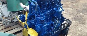
Tractor engine lubrication system
MTZ internal combustion engines are equipped with a lubrication system, which includes pipelines and special devices designed to deliver motor oils to the rubbing surfaces of working units and parts. Thanks to lubricants, the friction force between metal parts is significantly reduced, which helps to increase the service life of the entire engine.
MTZ tractors use a combined type lubrication system. Oil under pressure is supplied to the rubbing surfaces of the main and connecting rod bearings of the crankshaft, valves, gear wheels, camshaft parts, etc. Other components and parts are lubricated by splashing.
Main parts and components of the lubrication system:
- oil gear pump;
- oil radiator;
- centrifugal type oil purification filter;
- connecting tubes and devices;
- devices that monitor the level of temperature, pressure, and level of lubricants in the system.
Purpose of engine mechanisms
Let's consider the purpose of tractor engine mechanisms:
- The crank mechanism is responsible for perceiving the pressure force of gases that heat up during the combustion of the air-fuel mixture and then convert one type of movement into another, transmitting it to the crankshaft. Structurally, it consists of a cylinder, a piston with rings, a connecting rod, a crankshaft and a crankcase flywheel.
- The distribution mechanism is designed for the timely admission of the air-fuel mixture or air flows into the cylinder, as well as the release of exhaust gases. This mechanism consists of a camshaft, valves and spring mechanism, rocker arms, rods and pushers.
Additionally, to understand the operation of the tractor engine mechanisms, one should consider its main systems:
- Power and regulation are provided by the supply of the required volumes of fuel-air mixture with a certain composition.
- The cooling system is able to maintain optimal thermal conditions of the motor.
- The lubrication system supplies oil fluid to engine parts that are characterized by friction and increased wear due to friction.
- The ignition system of carburetor engines performs the process of igniting the working mixture inside the cylinder.
- The starting system is responsible for starting the engine.