Clutch adjustment YAZM 238
Adjusting the Yamz 238 clutch. Possible malfunctions and ways to destroy the problem. Detailed instructions for action.
The clutch is a mechanism that is constantly under stress. It reaches its maximum values at the moment of starting to move or changing gears. It is very important that the clutch is adjusted correctly - this guarantees long-term performance of both the mechanism itself and the safety of other transmission parts. This rule especially applies to the YaMZ 238 clutch, let's figure out why.
Clutch YaMZ 238
Design features
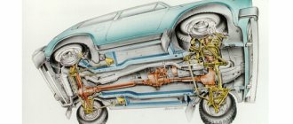
The clutch of this model is usually installed on heavy, powerful equipment.
YaMZ 238 is a dry double-disc friction-type clutch; the mechanism’s cylindrical springs are peripherally located.
The engine power and the actual design features of the mechanism very often lead to the fact that an incorrectly configured clutch can easily fail. In order to avoid breakdowns, it is necessary to diagnose and adjust the YaMZ 238 clutch at least once every six months.
Required Clutch Maintenance
Every time you start maintenance of the clutch, you must adhere to a strict sequence so as not to miss anything important and notice the problem in time:
- The first step is to check and, if necessary, adjust the free play of the clutch responsible for engaging the clutch (the gap should be 3.2–4 mm).
- Next, you need to check the mechanism for lack of guidance. (check is carried out with the engine running in first gear and with the clutch disengaged).
If you find out that the value is far from the maximum norm, there is only one way out, adjusting the YaMZ 238 transmission.
Clutch adjustment
- The adjustment should begin by measuring the free play of the clutch pedal. For YaMZ 238 it should be from 34 to 43 mm. The value should be checked using a ruler, after bleeding air from the pneumatic system in advance. So, if something is not right, we proceed to adjustment. However, first make sure that the gap between the end of the rear cover of the valve body and the retaining ring is within the normal range - 3.5+0.2 mm. If necessary, adjust it too.
- Next, it is necessary to adjust the gap from the second driven disk to the thrust ring of the retraction arms. (it should be within 64 mm).
- Next, we adjust the gap using the thrust ring and the clutch bearing to engage the YaMZ 238 mechanism. Here the values fluctuate within 3.6 mm. Please note that complete absence of this clearance can lead to failure of the thrust bearing and malfunction of the driven disk.
If the measures taken do not help, and the clutch malfunction persists, most likely, adjustment is not a panacea and the mechanism will need to be replaced.
YaMZ 238 clutch diagram
Clutch replacement
First of all, in order to independently replace the YaMZ 238 clutch with a new one, you need specific skills and at least one assistant. If all this is available, then most likely there will be no serious problems. Let's get started:
- First you will have to remove the gearbox, this is necessary to get to the flywheel and clutch housing.
- Next, unscrew the fastenings of the casing to the flywheel and remove the release disk.
- We unscrew the automatic adjustment bars for the stroke of the middle disk and remove the split rings from the rod.
- Remove the driven, middle, first driven and driving clutch discs.
Done, now you can start installing the new clutch:
- We start by installing the first driven disk. It is placed with the elongated end of the hub towards the flywheel.
- Next, queue 1 and 2 disks.
- Then we install the middle drive disk with rods.
- We install the pressure plate and, using 8 bolts, center the driven disks relative to the crankshaft axis. Having found the desired position, we finally tighten the boots.
- Then you should put on the split rings and install the automatic release adjustment stop bars for the middle pressure plate in place.
- Make sure once again that everything is assembled correctly and that’s it – you can put the gearbox back in place.
In general, the process turns out to be very lengthy and labor-intensive. Depending on the situation, the work may take up to several days. And, most importantly, you should understand that errors in collection are unacceptable. Incorrectly installed parts can lead to destruction of the YaMZ 238 mechanism and damage to the gearbox. Therefore, if you are unsure of yourself, it is better to turn to specialists. Qualified workers will perform the replacement with the necessary guarantees.
Clutch care
In order for the clutch to work as long as possible and not fail unexpectedly, you must follow a few simple rules:
- Periodically check the free play of the pedal, and also lubricate the drive and clutch bearing.
- In order to reduce wear on the clutch elements, you should not keep your foot on the pedal for a long time and use clutch slipping to reduce the speed.
You may also like
Source: https://autodont.ru/transmission/cohesion/yazm-238
Service
Maintenance of this mechanism is carried out as follows:
- Carry out an external inspection of the pedal and, if necessary, adjust its free play.
- Bleed the hydraulic drive.
- Carry out diagnostics of the crankcase fastening elements and, if necessary, tighten the nuts.
- Carry out an external inspection of the tension spring device, lubricate the bearings and hydraulic coupling.
- Check the functionality of the clutch switch and the shaft sleeve.
- Inspect the fork and clutch pedal for wear and damage.
- Check the operation of the mechanism by changing the gears of the vehicle on the spot and during acceleration.
- Eliminate incorrectly set gaps between support rings and washers.
- Eliminate leaks in the system and lubricate all cylindrical elements with a special liquid.
- Check the gap between the rods and the piston part of the main cylindrical device.
How to make adjustments
Actions when adjusting the MAZ clutch:
- Adjust pedal free play. To do this, you need to put your foot on the pedal and squeeze the gas all the way. If necessary, reduce or increase the stroke of this device.
- Release the pedal and measure the distance to the lower mark of the coupling mechanism.
- The maximum stroke amplitude should not exceed 16 cm.
- Tighten all fasteners.
- Measure the pedal free play.
After the driver has adjusted the clutch mechanism, it is necessary to adjust the MAZ clutch basket:
- Place the transport on a special platform.
- Unscrew the mounting bolts that connect the gearbox and the car body.
- Remove the gearbox.
- Unscrew the screws of the push-type disk and remove it.
- Inspect the basket and replace damaged or worn parts.
- Adjust the position of the paws.
- Using the adjustment handle, set the paws to the positions shown in the MAZ repair manual.
- Tighten all mounting screws until they are secure.
- Reassemble the mechanism by repeating all steps in reverse order.
Repair and replacement of double-disc clutch MAZ
Articles Loading...
The clutch of the YaMZ-238 model is a double-disc, dry, friction type, with a peripheral arrangement of cylindrical springs.
The clutch housing 16 (Fig. 1), stamped from sheet steel, with the pressure disk 19 assembly is installed on the engine flywheel 20, and the driven disks 21 are installed on the splined part of the gearbox input shaft.
The front and rear driven discs are installed in a specific position, as shown in the figure.
The driven clutch discs are clamped by a constant force of cylindrical pressure springs 17 between the engine flywheel, the middle and pressure discs.
Thermal insulating gaskets 18 are placed under the springs on the pressure plate side. The pressure and middle drive disks are connected to the flywheel by four tires located on the outer surface of the disks.
When clamped, the driven disks transmit engine torque to the transmission input shaft.
The clutch is released using clutch 11.
The clutch with the bearing, moving towards the engine, moves the pressure disk away from the driven disk, transmitting force through four rigid pull-out levers 5. The working stroke of the clutch release clutch, taking into account free play, must be at least 18.2 mm (size “D”) .
[/su_box][/su_box]
The amount of free play is regulated by the clutch release mechanism. The thrust ring of the pull-out levers moves towards the gearbox by 27 mm due to the permissible wear of the friction linings.
Guaranteed clearances between the driven disks and the friction surfaces of the flywheel, middle drive and pressure disks when the clutch is disengaged as the linings wear are ensured by a mechanism for automatically adjusting the withdrawal of the middle disk, which consists of rods 1 fixed in each of the four spikes of the middle drive disk, split rings 2, to move along the rod which requires a certain force, thrust bars 4, which are bolted to the flywheel with the clutch casing, and disc springs 3 installed on the rod between ring 2 and bar 4.
When the clutch is released, the pressure plate 19 moves back at least 2 mm and releases the rear driven disk 21.
The middle drive disk 22, under the action of the spring 23, also moves back, until the ring 2 stops in the bar 4 through a disc spring, by an amount of 1.2+0.1 mm, freeing the front driven disk.
As the clutch friction linings wear out, the middle drive disk, under the action of the pressure springs of the pressure disk, moves to the flywheel, the rings 2 rest against the clutch housing, moving along the rods 1 and maintaining the size between the rings and the disc springs.
When the driven disc linings wear out, the end of the clutch release clutch will rest against the end of the gearbox input shaft bearing cover; in this case, replace the worn linings of the driven discs with new ones.
How to replace
Replacing the clutch is carried out in several stages:
How to remove
In order to dismantle the coupling mechanism, you must perform the following steps:
- Place the vehicle on a special platform or inspection hole.
- Remove the battery.
- Remove the air filter element.
- Remove the engine splash guards, which are located in the lower and side parts of the power unit compartment.
- Remove the front suspension cross member.
- Remove the front drive wheels.
- Drain the oil fluid.
- Disconnect the speed sensor using a screwdriver.
- Remove the reverse switch.
- Remove the engine harness holder.
- Unscrew the mounting bolts and remove the starter housing.
- Disconnect the engine mounts from the gearbox bracket.
- Move the clutch back.
- Remove the input shaft of the mechanism.
- Unscrew the mounting bolts from the coupling mechanism housing. The bolts are unscrewed one by one, in 2-3 steps.
- Remove the pressure plate along with the casing.
Assembly
Clutch mechanism assembly steps:
- Assemble the driven disk. To do this, it is necessary to attach friction linings to a plastic spring device.
- Assemble the pressure plate. You need to lubricate the rollers with a special liquid, place them in the hole of the pull handles, insert the lever into the groove that is located on the pressure-type disk, and install the finger. Attach the support forks to the levers and secure them with cotter pins.
- Assemble the pressure disk with the casing. This must be done under a press that can compress the springs and screw the bolts into the support forks. A driven type disk is placed under the press, and a pressure disk is placed on top. Heat-insulating washers and the spring mechanisms themselves are installed on special protrusions. Press the casing using a press and tighten the mounting bolts.
- Installing discs into the clutch housing.
Procedure for installing the clutch:
- Install the driven disc so that the extended end of the hub faces the flywheel.
- Install the drive disk element with rods.
- Install a second driven disk with the elongated end of the hub pointing towards the gearbox.
- Install the pressure plate.
- Attach the cut adjusting rings to the structure.
- Install the stop bars and secure them with the casing.
- Install the clutch mechanism on the flywheel, check the gap between the thrust rings and washers by engaging the clutch mechanism.
How to install disks
Many drivers are interested in how the clutch disc is installed on a MAZ.
In order to install clutch discs, you must:
- Disconnect the driveshaft.
- Remove the brake drum and pads from the wheels.
- Using a wrench, unscrew the fasteners from the axle shafts and pull them out.
- Unscrew the screws that adjust the position of the propeller shaft flange and gearbox.
- Disconnect the contacts of the sensor wires, which is responsible for turning on the reverse lights.
- Using a 12mm wrench, unscrew the mounting screws from the clutch mechanism protective cover.
- Remove the casing.
- Using a small crowbar, pry the gearbox housing away from the power unit.
- Remove the basket from the flywheel.
- Secure the flywheel.
- Remove damaged disk elements and replace them with new ones. The driven clutch disc should be directed towards the gearbox, and the pressure disc should be placed so that the hub is directed towards the engine.
- Reassemble the coupling mechanism by performing all steps in reverse order.
Installation and adjustment of the Yamz double-disc clutch
The clutch of the YaMZ-238 model is double-disc, dry, friction type, with a peripheral arrangement of cylindrical springs
The clutch housing 16 (Fig. 1), stamped from sheet steel, with the pressure disk 19 assembly is installed on the engine flywheel 20, and the driven disks 21 are installed on the splined part of the gearbox input shaft.
The front and rear driven discs are installed in a specific position, as shown in the figure.
The driven clutch discs are clamped by a constant force of cylindrical pressure springs 17 between the engine flywheel, the middle and pressure discs.
Thermal insulating gaskets 18 are placed under the springs on the pressure plate side. The pressure and middle drive disks are connected to the flywheel by four tires located on the outer surface of the disks.
When clamped, the driven disks transmit engine torque to the transmission input shaft.
The clutch is released using clutch 11.
The clutch with the bearing, moving towards the engine, moves the pressure disk away from the driven disk, transmitting force through four rigid pull-out levers 5. The working stroke of the clutch release clutch, taking into account free play, must be at least 18.2 mm (size “D”) .
[/su_box][/su_box]
The amount of free play is regulated by the clutch release mechanism. The thrust ring of the pull-out levers moves towards the gearbox by 27 mm due to the permissible wear of the friction linings.
Guaranteed clearances between the driven disks and the friction surfaces of the flywheel, middle drive and pressure disks when the clutch is disengaged as the linings wear are ensured by a mechanism for automatically adjusting the withdrawal of the middle disk, which consists of rods 1 fixed in each of the four spikes of the middle drive disk, split rings 2, to move along the rod which requires a certain force, thrust bars 4, which are bolted to the flywheel with the clutch casing, and disc springs 3 installed on the rod between ring 2 and bar 4.
When the clutch is released, the pressure plate 19 moves back at least 2 mm and releases the rear driven disk 21.
The middle drive disk 22, under the action of the spring 23, also moves back, until the ring 2 stops in the bar 4 through a disc spring, by an amount of 1.2+0.1 mm, freeing the front driven disk.
As the clutch friction linings wear out, the middle drive disk, under the action of the pressure springs of the pressure disk, moves to the flywheel, the rings 2 rest against the clutch housing, moving along the rods 1 and maintaining the size between the rings and the disc springs.
When the driven disc linings wear out, the end of the clutch release clutch will rest against the end of the gearbox input shaft bearing cover; in this case, replace the worn linings of the driven discs with new ones.
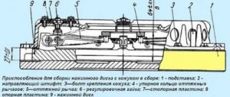
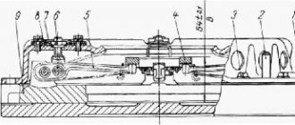
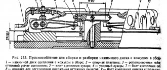
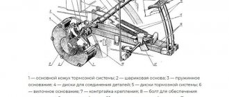
Adjusting the position of the thrust ring of the pull-out levers
When assembling the pressure plate and housing assembly, adjust the position of the thrust ring.
This adjustment is made in a device having an installation size of 27 ± 0.1 mm (Fig. 2) with adjusting nuts 6 pull-out levers with the casing and pressure disk in a fixed position.
By adjusting, ensure dimension “B” is equal to 64 ± 0.1 mm, while the thrust surfaces of all four release levers 5 must simultaneously touch the thrust ring 4. A misalignment of the thrust ring will lead to uneven release of the pressure plate when the clutch is disengaged or its abnormal operation.
After adjusting the position of the thrust ring using the adjusting nuts 6, install the locking 7 and support plates 8 of the adjusting nuts. Tighten all eight bolts securing the locking and support plates, installing spring washers under the bolt heads.
In the case of using a pressure plate with a casing complete with driven disks after repair, on which friction linings with a thickness of 4.15 mm are installed, when adjusting the position of the thrust ring, set dimension “B” to 67+0.1 mm.
Adjusting the MAZ clutch
In previous articles, we discussed the issue of repairing the MAZ clutch and its design.
Today we offer some useful tips to help you adjust the MAZ clutch.
We will also tell you how to bleed the clutch on a MAZ.
Instructions for adjusting the MAZ clutch
A truck clutch is a double-disc friction-type device that is installed in the truck crankcase. function - disconnecting the crankshaft of the truck engine from the gearbox. Also, the clutch smoothly connects the elements (gearbox and engine crankshaft) when changing gears. However, over time, the mechanisms wear out. Therefore, the MAZ clutch is adjusted. To do this, we recommend buying:
- Socket and open-end wrenches;
- Vernier calipers and ruler.
So, adjusting the MAZ clutch is done as follows. First you need to ensure the maximum correct gap between the surfaces of the mechanism. To do this, we will adjust the amount of waste of such an element as the drive disk. Note the gap between the adjusting nut and the end of the valve body cover. We also recommend that you adjust them.
Adjusting the MAZ double-disc clutch requires patience. Therefore, we continue further. We proceed to dismantling the flywheel housing and its hatch cover. All this is necessary to vary the amount of withdrawal of the middle disk (driver). Adjusting the MAZ clutch at this stage is done as follows:
- Engage the clutch;
- Set the gearshift lever to neutral;
- Turn the engine flywheel;
- Unscrew the lock nuts of the screws;
- Screw the 4 screws into the middle drive disk until they stop.
The adjustment of the MAZ double-disc clutch is still not completed.
Next, we continue to rotate the flywheel, after unscrewing the screws 1 turn. Then we secure these elements with locknuts. There is one point - adjusting the MAZ double-disc clutch requires constant holding of the screw with a tool. This way the adjusted gap cannot go astray. We continue with the adjustment. Using a ruler, measure the gap between the nut and the end of the rear valve cover. Remember that it should not exceed 3.3 mm.
Adjusting the MAZ double-disc clutch involves working with exactly this nuance. To adjust the gap, loosen the locknut of the adjusting nut. After fixing the required gap (3.3-3.7 mm), tighten the fasteners. That's it, the adjustment of the MAZ double-disc clutch is done.
How to bleed the clutch on a MAZ?
Adjusting the MAZ double-disc clutch does not take much time. However, problems sometimes arise with bleeding the clutch.
Before thinking about how to bleed the clutch on a MAZ, we advise you to make sure that this procedure is necessary. One of the main reasons that the PSU needs to be pumped is poor gear shifting. That is, in this case, the clutch does not engage completely, since air has entered the vehicle’s hydraulic line. Therefore, all car owners need to know how to bleed the clutch on a MAZ.
Here are a few instructions to help you.
Before pumping the MAZ clutch, gradually fill the hydraulic drive reservoir with fluid to the level of one and a half centimeters (1-1.5 cm).
It is important to clean the cylinder exhaust valve of any contamination. Remove the protective cap from its head. We put a rubber hose on the element. Usually it is included in MAZ accessories.
How to bleed the clutch on a MAZ? Just! The main thing is desire and time. Therefore, we continue the pumping process. Gradually lower the free end of the hose into the hydraulic fluid. I emphasize that it must be poured to the middle in a liter container. Only after this do we begin to lightly press the car’s clutch pedal. There is a 1-2 second interval between pressing. Press about 4 times.
Advice on how to bleed the clutch on a MAZ is completely meaningless if you do not understand the essence of the process. You can press the pedal as much as you like, but... you won’t achieve the desired effect.
Therefore, when pressing 1 time, we keep the pedal depressed. At the same time, you need to unscrew the air release valve approximately ½ turn. Thus, with 2, 3 and 4 presses of the pedal, the pressure through the hose will expel some of the liquid and, naturally, air. If you don’t see any bubbles in the liquid, stop pressing the pedal.
In this article, we told you how to bleed the clutch on a MAZ in an intelligible and understandable way. And finally, let’s emphasize something.
During pumping, it is extremely important to monitor the fluid level in the tank. If you see a decrease of more than 2/3, add liquid.
If the adjustment of the MAZ double-disc clutch and its bleeding are completed, be sure to add fluid to 1 -1.5 cm from the top edge.
Remember one rule - read how to bleed the clutch on a MAZ, did the procedure and be sure to measure the stroke of the hydraulic booster rod at maximum at the end. (norm 18 mm).
Source: https://mazprice.ru/blog/regulirovka-stsepleniya-maz/
Hydraulic clutch release drive URAL-5557
Main cylinder 7 (Fig. 27) is installed in the engine compartment and is mounted on a bracket to the front panel of the cab. The piston is acted upon by pusher 13 (Fig. 28), which is connected through a lever to pedal mechanism 8 (see Fig. 27).
When the clutch pedal is acted upon, fluid pressure from the master cylinder is transmitted through tube 31 and hose 24 to the pneumohydraulic booster (PSU). In the PSU, the liquid presses on the rod and at the same time opens the valve of the pneumatic system.
The pneumatic part consists of a cylinder 22 with a capacity of 8 liters, installed on the rear bracket of the batteries, a single safety valve 21, and pipelines. Power is supplied from a separate circuit of the pneumatic system.
A single safety valve is installed on the cylinder and is designed to separate the air line running from a separate circuit of the pneumatic system to the cylinder and maintain pressure in it regardless of the pressure drop in the main circuits. The cylinder is equipped with a condensate drain valve and control valve 18.
The air supply to the CCGT unit is carried out by tube 17 and hose 16.
Clutch cylinder. The design of the master cylinder is shown in Fig. 28. If repairs are necessary during assembly, install ring 14 as shown in Fig. 28.
Lubricate the inner surface of the cylinder, rubber rings and cuff with brake fluid during assembly.
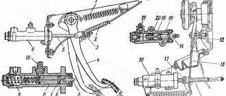
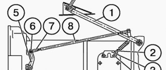
Rice. 27. Clutch control drive:
1 — compensation tank; 2 — tank cover; 3 - bolt; 4 - nut; 5,14,23 — brackets; 6 — cylinder stop; 7 — main cylinder; 8 — pedal mechanism; 9.32 — springs; 10 — brake pedal; 11—clutch pedal stop; 12.15 — brake pedal rods; 13—brake valve control lever; 16,24,33 — hoses; 17,19,31—clutch drive tubes; 18 — control valve; 20 - triple safety valve; 21 — single protective valve; 22 — air cylinder; 25 — clutch fork shaft lever; 26 — rod; 27 — pneumohydraulic amplifier (PGU); 28 — PSU bleeding valve; 29 — bracket thrust bolt; 30 — clutch pedal; L= 185-200 mm; L1 = 254 mm; L2 =30-40 mm
Pneumohydraulic clutch booster (PGU)
contains a housing 1 (Fig. 29), inside of which a piston 5 and a rod 4 are located. The piston and rod are movably sealed in the housing and can move in the axial direction. The piston is sealed in the body using a rubber cuff 9, and the rod is sealed with two rubber sealing rings 3.
How to adjust the MAZ clutch - All about everything
In previous articles, we discussed the issue of repairing the MAZ clutch and its design.
Today we offer some useful tips to help you adjust the MAZ clutch.
We will also tell you how to bleed the clutch on a MAZ.
Repair and replacement of double-disc clutch MAZ
Source: https://kakprostoyes.ru/kak-otregulirovat-sceplenie-maz.html
Adjusting the Yamz 238 double-disc clutch with your own hands
Articles Loading...
The clutch of the YaMZ-238 model is a double-disc, dry, friction type, with a peripheral arrangement of cylindrical springs.
The clutch housing 16 (Fig. 1), stamped from sheet steel, with the pressure disk 19 assembly is installed on the engine flywheel 20, and the driven disks 21 are installed on the splined part of the gearbox input shaft.
The front and rear driven discs are installed in a specific position, as shown in the figure.
The driven clutch discs are clamped by a constant force of cylindrical pressure springs 17 between the engine flywheel, the middle and pressure discs.
Thermal insulating gaskets 18 are placed under the springs on the pressure plate side. The pressure and middle drive disks are connected to the flywheel by four tires located on the outer surface of the disks.
When clamped, the driven disks transmit engine torque to the transmission input shaft.
The clutch is released using clutch 11.
The clutch with the bearing, moving towards the engine, moves the pressure disk away from the driven disk, transmitting force through four rigid pull-out levers 5. The working stroke of the clutch release clutch, taking into account free play, must be at least 18.2 mm (size “D”) .
[/su_box][/su_box]
The amount of free play is regulated by the clutch release mechanism. The thrust ring of the pull-out levers moves towards the gearbox by 27 mm due to the permissible wear of the friction linings.
Guaranteed clearances between the driven disks and the friction surfaces of the flywheel, middle drive and pressure disks when the clutch is disengaged as the linings wear are ensured by a mechanism for automatically adjusting the withdrawal of the middle disk, which consists of rods 1 fixed in each of the four spikes of the middle drive disk, split rings 2, to move along the rod which requires a certain force, thrust bars 4, which are bolted to the flywheel with the clutch casing, and disc springs 3 installed on the rod between ring 2 and bar 4.
When the clutch is released, the pressure plate 19 moves back at least 2 mm and releases the rear driven disk 21.
The middle drive disk 22, under the action of the spring 23, also moves back, until the ring 2 stops in the bar 4 through a disc spring, by an amount of 1.2+0.1 mm, freeing the front driven disk.
As the clutch friction linings wear out, the middle drive disk, under the action of the pressure springs of the pressure disk, moves to the flywheel, the rings 2 rest against the clutch housing, moving along the rods 1 and maintaining the size between the rings and the disc springs.
When the driven disc linings wear out, the end of the clutch release clutch will rest against the end of the gearbox input shaft bearing cover; in this case, replace the worn linings of the driven discs with new ones.
Torsional vibration damping and power take-off mechanism
Power units can be equipped with a mechanism for damping torsional vibrations and power take-off (Fig. 3), designed to dampen resonant torsional vibrations and protect transmission systems from destruction.
The mechanism is installed on the engine flywheel and consists of a pressure flange 1, a driven disk 2 with friction linings and a mechanism for damping torsional vibrations, packages of disc springs 5 and stepped bolts 6.
Driven disk 2 is constantly pressed to flywheel 3 through flange 1 by packages of disc springs 5 assembled on stepped bolts 6.
The step bolts are screwed into the flywheel until they stop. When installing stepped bolts, sealant UG-6 TU 6-01-1285-84 is applied to their threaded part, tightening is carried out with a force of 49-59 Nm (5-6 kgcm).
The number of packages of disc springs and bolts is selected so that the friction moment they create allows the transmission of torque from the flywheel to the power take-off shaft up to 1700 Nm (170 kgcm).
When the driven disk is loaded with a torque of more than 1700 Nm (170 kgcm), the force of the springs is not enough to hold the driven disk and it rotates relative to the flywheel and thereby protects further kinematic connection from destruction.
During operation, the mechanism does not require maintenance.
Possible malfunctions of the driven disk during operation are similar to malfunctions of the clutch driven disk.
Premature slipping of the driven disk can be eliminated by installing additional packages of disc springs together with the bolt and further checking the friction torque in the following order:
1. Lock the engine flywheel.
2. Load the driven disk of the mechanism with a torque of less than
1700 Nm (170 kgcm). the disc should not rotate relative to the flywheel.