Steering of the MTZ 82 tractor - steering column
The steering of the MTZ 82 tractor is necessary to create and support straight-line movement, as well as to turn the tractor with its front steered wheels.
Device
The steering system consists of a steering gear, a control linkage and a steering gear. All MTZ 82 tractors are equipped with power steering. The steering linkage is responsible for turning the right and left front wheels at different angles, at which the rear and front wheels turn relative to a common center of rotation located on the extension of the axis of the rear wheels. As a result, the wheels roll in concentric circles without lateral sliding. The steering linkage consists of two transverse steering rods connected to each other by a bipod; front axle beams and two swing arms.
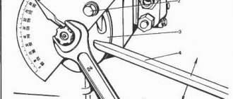
Front axle MTZ 82 (top view): 1 — tie rod end; 2 - lock nut; 3 — steering rod pipe; 4 - bipod; 5 - finger; 6 - rotary lever.
When the tractor is moving along a straight path, the bipod is in the middle position. The power steering piston stroke limits the extreme positions of the bipod when turning. The maximum rotation angle of the inner wheel is 40º, while the outer wheel rotates at an angle of 30 degrees. The steering rod device consists of a connecting pipe and a pair of ends, one of which is with a right-hand thread, and the second with a left-hand thread.
Steering diagram of the MTZ 82 tractor: 1 - steering wheel; 2 — handwheel; 3 — steering shaft; 4 - screw; 5 — intermediate shaft; 6 — steering column pipe; 7 - earring; 8 and 12 — cardan joints; 9 - stand; 10 - middle shaft; 11 — intermediate support; 13 — front shaft; 14 — splined bushing; 15 - screw; 16 — right wall of the rack; 17 — clamp; 18 — spring; 19 — handle; 20 - pin; 21 and 24 - nut; 22 — bushing; 23 — shock absorber; 25 - lock nut.
Tie rod end
The tips are screwed into the threaded holes of the pipe and secured with locknuts. In the internal cavity of the tip there is a spherical joint consisting of a ball pin and a pair of liners (nylon and rubber). At the factory, the hinge is filled with a special lubricant that does not require replenishment during operation. A rubber boot and a rubber adjusting plug that tightens the joint liners protect the joint from dirt, moisture and dust. The tapered ends of the threaded ball pins are inserted into the holes of the bipod and swing arms, tightened with slotted nuts and cottered.
Steering gear drive and steering column MTZ 82
The steering gear drive is used to transmit rotation from the tractor steering wheel to the steering gear and power steering. The force is transmitted using shafts connected to each other by cardan joints.
The steering column is adjustable in height, and it is also possible to tilt it forward along the tractor. The height of the steering wheel is adjustable for comfortable control, and the tilt of the steering column is adjustable for free exit and entry from the cabin.
The steering column tube is connected to an earring, which in turn is pivotally connected to the rack using two screws, the axes of which are aligned with the axis of the hinge cross. This allows the steering column to rotate relative to the post bolted to the front wall of the cab. Fixing the steering drive in the cabin, mounted on the frame of the tractor on shock absorbers, reduces the transmission of vibrations to the steering wheel.
The latch, which fits into a groove in the right wall of the pillar and is pressed by a spring, holds the steering column in the lower working position. In order to turn the steering column, you need to pull the handle towards you and the lock will come out of the groove. After which the column will easily turn upward, while the clamp will slide along the surface of the rack wall. In the upper, non-working position, the steering column is not fixed, but is held due to the friction force of the clamp on the surface of the rack wall.
The steering wheel or simply the steering wheel of the MTZ 82 tractor is mounted on the splines of a hollow shaft, inside of which there is a screw connected to a plastic flywheel. The screw is screwed into the nut into which the pin is mounted. The pin fits into the longitudinal groove of the intermediate shaft and blocks the rotation of the nut. The shaft and nut are provided with braces adjacent to each other. When the screw is screwed in, mutual wedging occurs along the bevels of the shaft and nut and they are pressed against the opposite inner walls of the intermediate shaft. This completely eliminates unauthorized axial movement of the steering wheel together with the shaft.
The force applied to the steering wheel is transmitted by the nut and shaft through a pin to the intermediate shaft and then through the shafts and hinges to the splined bushing, which is mounted on the splines of the power steering worm and secured with a pinch bolt.
Adjusting the steering column of the MTZ 82 tractor
The position of the steering column is height adjustable within a range of 120 mm. The tractor driver can set the steering wheel to a comfortable position by turning the flywheel 3-5 turns counterclockwise; Next, move the steering wheel along with the shaft in height to the required position and screw the handwheel back until it stops.
The intermediate shaft rotates in the steering column tube using nylon bushings installed in rubber shock absorbers to reduce the level of vibration of the steering wheel. The axial movement of the intermediate shaft is limited by a nut and a locknut. While operating the tractor, you should occasionally check the condition of the steering drive components, the tightness of threaded connections, and lubricate the hinges every 960 hours.
Steering faults
| Possible causes and symptoms of malfunction | Remedies |
| Oil foaming in the booster system: | |
| a) Insufficient oil in the amplifier housing | Check the oil level, add if necessary |
| b) Air penetration into the system | Check the suction line, find the leak and fix it. |
| The safety valve is not adjusted correctly | Adjust the valve |
| Increased oil leakage in the pump | Replace the pump |
| Jamming in the worm-sector engagement | Adjust the engagement |
| Sticking in the moving joints of the steering drive or front axle | Eliminate jamming |
| Increased instability of the front wheels | |
| The worm nut is loose | Tighten the nut to a torque of 2 kgf*m, loosen 1/6 of a turn and secure with a cotter pin |
| Increased play in the tapered bearings of the front wheels or in the steering linkage joints, the toe-in of the front wheels is impaired | Adjust |
| The tightening of the nuts securing the bipod, sector or swing arms is loose | Tighten the nuts |
| Increased free play of the steering wheel | |
| The gap in the worm-sector engagement has been increased | Adjust |
| Increased play in the joints of the steering wheel drive cardan couplings | Replace worn parts |
| The worm nut is loose | Adjust the tightening of the nut |
Steering maintenance and repair
Maintenance consists of monitoring the oil level in the housing and the absence of leakage at the power steering connections, checking various threaded connections, mounting the bipod, steering rods; in periodic lubrication of universal joints, changing oil, washing the oil filter.
Make sure that when washing the oil filter, checking the oil level and filling it, no dirt gets into the power steering system.
The oil filter is washed every 960 hours of operation in this sequence: 1. disconnect the oil line from the pressure reducing valve and cover; 2. remove the top cover, having previously unscrewed all the bolts; 3. Disconnect the remaining two oil lines from the pressure reducing valve and, holding the filter with your hand, unscrew the valve to release the filter; 4. Rinse the filter in diesel fuel or gasoline, completely removing dirt from its internal cavity. At the same time, tighten the nut securing the sector to the shaft and inspect the rack-sector gearing.
If the gap between the teeth of the rack and the sector exceeds 0.3 mm, then the engagement must be adjusted. To do this, unscrew the four bolts securing the ABD housing rack stop and, removing the gaskets in pairs, reduce the engagement gap to 0.1-0.3 millimeters. Using a feeler gauge, measure the gap between the teeth.
Installing the filter occurs in the reverse order. After installing the cover, it is necessary to unscrew the locknut in advance and tighten the bolt that regulates the axial movement of the rotary shaft until it stops. Next, unscrew the bolt 1/10-1/8 of a turn and secure with a nut.
Adjusting the worm-sector engagement and tightening the worm nut
The free play of the steering wheel when turning the front wheels of a tractor standing on a hard surface with the engine running should not exceed 30º. If the free play exceeds this value, then you should inspect and, if necessary, tighten the nuts of the swing arms and coulters until they stop, and also adjust the steering linkage joints. If these actions do not solve the problem, then you should adjust the gap in the worm-sector engagement and the tightening of the worm nut.
To adjust the sector-worm engagement, perform the following steps: 1. using a jack, lift the front axle or disconnect the steering rods from the bipod; 2. Loosen the bolt securing the adjusting eccentric sleeve and turn it clockwise until the worm stops against the sector teeth. Next, with the diesel engine running, rotate the steering wheel. If there is noticeable jamming in the worm-sector engagement, then turn the sleeve counterclockwise until the jamming disappears when turning the steering wheel. 3. Tighten the adjusting sleeve mounting bolt and connect the steering rods to the bipod.
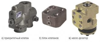
Design and principle of operation
The cast iron housing of the MTZ 80 (82) power steering is located on the front frame beam between the front front wall of the hood and the diesel engine cooling radiator of the machine. The unit is a mechanism with a worm gearbox, equipped with an autonomous hydraulic system with a spool for controlling the flow of working fluid, a left-hand rotation gear hydraulic pump NSh-10-L-U GOST 8753-71, a double-acting power cylinder and a safety valve. The system's hydraulic pump is driven by the engine timing gear.
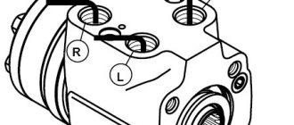
A worm is installed in the amplifier body, connected by turns to the sector and its end part to the valve spool of the assembly. At the ends of the spool there are thrust bearings, into which the plungers rest under the pressure of the springs. At the same time, the outer sides of the plungers rest against the housing parts of the distributor. Plungers and springs hold the spool in the neutral position through bearings. When the steering wheel rotates, the worm begins to move the sector in turns, turning the bipod shaft. The resulting resistance of the wheels is transmitted through the mechanism to the worm, forming a force that moves it axially forward or backward depending on the direction of rotation. By its displacement, the worm interacts with the valve spool of the assembly, moving it relative to the axis. Thus, the spool controls the flow of oil under pressure. When moving straight, the distributor spool, spring-loaded, is in the neutral position, the pressure supplied by the pump is released into the amplifier housing, which is the hydraulic tank of the system.
By rotating the steering wheel, the worm moves the spool, which opens the lines of the cavities of the power cylinder with its belts. Moreover, depending on the direction of rotation, one cavity is connected to a line supplying oil under pressure, the other to a drain. The spool drops pressure into the cylinder cavity only during direct rotation of the steering wheel. When the steering wheel stops, the worm stops acting on the distributor spool, which, under the force of the springs, takes a neutral position, dumping oil into the drain cavity.
The piston of the cylinder 25 interacts through a rod with a rack 14 connected to sector 12 . When the spool supplies pressure to one of the cavities, the rod transmits force to the rack moving the sector, facilitating the rotation of the shaft 28 connected to the bipod 13 . The working pressure in the hydraulic system is 2-4 MPa. By turning the steering wheel to the maximum angle of rotation, the pressure reaches its maximum value of 8 mPa and is limited by safety valve 7 .
The driver’s feeling of “Road Feeling” of resistance to turning during steering is provided by the pressure from the discharge channel in the cavities with springs acting on the plunger. When controlled without force, the worm does not interact with the spool and the hydraulic system does not participate in the amplification.
Additionally, the unit is equipped with a differential automatic locking sensor located in the rack stop. The device includes a spool 21 , a rotary valve 18 with a flywheel, a pusher and a probe 20 . An unregulated pressure reducing valve maintains a pressure of 0.7-0.9 MPa in the locking hydraulic system. The device provides differential locking when driving straight and automatically turns it off when the wheels are turned more than 8 ̊.