Electrical wiring of the T-40 tractor. Wiring diagram :: Tractor T-40
» Electrical equipment » Electrical wiring of the T-40 tractor. Wiring diagram
Electrical wiring of the T-40 tractor. Wiring diagram
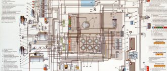
The electrical wiring of the T-40 tractor is implemented using a single-wire circuit for connecting electrical equipment, which requires extreme attention to the wiring insulation and the method of fastening the wires. If the insulation is damaged, the wires may come into contact with the tractor ground, leading to short circuits.
To facilitate wiring installation during repair or operation of the tractor, special plug connectors and connecting connectors (installation devices) are provided, and the wire insulation has a different color. Most of the wires are combined into separate bundles tied with ties. If there are several connections in an electrical wiring circuit, all the wires of this circuit have the same color, which makes their installation easier.
To prevent damage to the electrical equipment of the T-40 tractor, it is necessary to regularly check the condition of the electrical wiring and eliminate various damage such as sagging, chafing, etc. Pay utmost attention to the tightness of the connections of the wires with the connecting panels and sockets. If damage to the insulation is detected, the electrical wiring must be cleaned of dirt and oxidation and securely wrapped with electrical tape. Regularly clean the wires of dirt, oil and fuel.
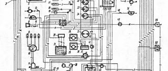
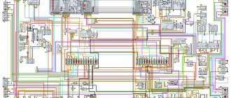
Wiring diagram of the T-40 tractor: 1 - front lights; 2 — headlights; 3 — connecting panels; 4 — sound signal; 5— generator; 6—glow plug; 7 — oil temperature indicator sensor; 8 — starter; 9 — batteries; 10—mass switch; 11 — portable lamp socket; 12— portable lamp; 13 — starter blocking relay; 14 — windshield washer pump; 15— windshield washer switch; 16 — heater fan switch; 17 — plug connector; 18— windshield wiper; 19— fan; 20 — lampshade; 21 — lamp switch; 22 — instrument lighting lamps; 23 — headlight light switch; 24 — high beam warning lamp; 25 - central light switch; 26 — fuse block; 27 — horn switch; 28 — direction indicator switch; 29 — turn signal indicator lamp; 30 — turn signal switch; 31 — rear headlight switch; 32 — oil temperature indicator; 33 - current indicator; 34 — fuel level indicator; 35 — fuel level sensor; 36 — brake signal switch; 37— control lamp of the “ground” switch; 38 — lock switch; 39 — glow plug control element; 40 - additional resistance; 41 — starter relay; 42 — glow plug and starter switch; 43 — rear lights; 44 — rear lights; 45 — plug socket; 46 — license plate light.
20.08.2018
T-40 engine
Engine structure of the T-40 tractor: piston, crankshaft, cylinders
Further…
Power transmission
Design and operation of the power transmission of the T-40 tractor
Further…
Supply system
Design of the T-40 tractor power system: nozzles, fuel injection pump, etc.
Further…
Electrical equipment
Electrical equipment T-40: diagrams and device.
Further…
Hydraulics
Hydraulic system: malfunctions and repairs.
Further…
tractor-t40.ru
Recommendations for use
During welding work, to prevent damage to the generator with a built-in integral voltage regulator, you need to disconnect it from ground.
To increase the life of the mechanism, follow these tips:
- Do not connect the battery terminals in reverse polarity, which will damage the generator voltage regulator;
- You should not start if the voltage in the system is more than 13 V;
- It is strictly forbidden to wash the generator with solutions that contain degreasers, as well as with gasoline;
- Do not allow the generator to dry out or overheat above 90 ºC
- Do not test the mechanism by shorting the terminal to ground and the voltage regulator terminal;
- You cannot check the presence of current with the battery removed;
Important! The general condition of the generator can be checked using the ground indicator lamp, which is located on the left of the instrument panel.Before starting the engine and turning on the ground, the lamp should light up; if everything is in order, it will go out within a couple of seconds.
The warning light comes on after turning on the ground before starting the engine. If the generator is working properly, the warning light will go out after the engine starts.
Tractor T-40, T-40A. Tractor electrical equipment
content .. 80 81 82 83 84 85 86 87 88 89 ..
Tractor T-40, T-40A. Tractor electrical equipment
The electrical equipment installed on the T40 and T40A tractors is intended for starting the engine and normal operation of the tractor and agricultural unit at night, both when performing agricultural work and when using the tractor for transport work. The tractor's electrical equipment is connected via a single-wire wiring system, in which the metal parts (“Ground”) of the tractor itself serve as the negative drive.
Each source and each consumer of electrical energy is connected by one pole to the “Ground”. Voltage (nominal) in the electrical system is $12.
The tractor electrical system includes the following devices and units (see diagram, Fig. 74):
1. DC generator 3 with relay regulator 9 and batteries 29, which are a source of electrical energy.
2. Starter 34 with relay 2 and starter switch 30, which serves as an engine starting device.
3. Headlights 1, rear lights 21, double-sided lights 23 - direction indicators, side indicators, brake lights, license plate light 22, ceiling lamp 24, warning lamp for broken fan belt 7, as well as a portable lamp are used for lighting and light signaling.
4. Ammeter 11, showing the amount of charging or discharge current.
5. Sound signal 6 with switch 13.
6. Connecting panels 5, ground switch 28, fuse and connecting wires.
The tractor can be equipped with a starting motor when, instead of the main starter, in addition to the listed equipment, a starting motor starter switch and a starting motor stop button are installed.
The electrical diagram of a tractor with a starting motor is shown in Fig. 75.
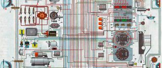
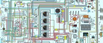
Rice. 74. Electrical diagram of a tractor equipped with a starter:
1 — headlights; 2 - starter relay; 3 - generator; 4 — temperature indicator sensor; 5 - connecting panels: 6 - sound signal; 7 - warning lamp for broken fan belt; 8 — oil temperature indicator; 9 — relay-regulator; 10 — portable lamp socket; II - ammeter; 12 - fuse; 13 —* signal switch; 14 — direction indicator switch; 15 — “Stop” switch; !6 — rotation signalizer; !7 — headlight switch; 18 — lamp and fan switch; 19 — plug socket; 20 - fan; 21 — rear lights; 22 — license plate lamp; 23 — double-sided lantern; 24 — cabin ceiling; 25 — instrument panel lighting lamp; 26 — switch for the instrument panel lighting lamp; 27 — light switch for rear headlights and side lights; 28 — “Mass” switch; 29 — battery; 30 — glow plug and starter switch; 31 - additional resistance; 32 — glow plug control element; 33 - glow plug; 34 - starter.
Designation of wire colors in the diagram: B - white; K - red; G - blue; 3 - green; F - yellow; Cor. brown; F - purple; H - black Next to the color designation, the numbers indicate the wire cross-section.
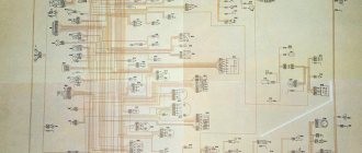
Rice. 75. Electrical diagram of a tractor equipped with a starting motor: 1 - front headlights; 2 - starter relay; 3 - warning lamp for broken fan belt; 4 - generator; 5 — temperature indicator sensor; 6 — connecting panels; 7 — oil temperature indicator; 8 — instrument panel lighting lamp; 9 - switch for instrument panel lighting; 10— fuse; 11 — portable lamp socket; 12 — cabin ceiling; 13 — lamp and fan switch; 14 - fan; !5 — direction indicator switch; 16 - turn signal; 17 — front light switch * fa^>; 18 — switch for rear headlights and side lights; 19 — “Stop” switch; 20 — plug socket; 21 double-sided lanterns; 22— rear lights; 23 — license plate lamp; 24 — “Mass” switch; 25 - battery; 26 — glow plug; 27 — signal switch; 28 — glow plug control element; 29 — sound signal; 30 - additional resistance; 31 — starting motor starter; 32 — spark plug; 33 — starting motor stop switch; 34 — starting motor starter switch; 35 - ammeter; 36 — relay-regulator; 37 — glow plug and starter switch; 38 - magneto. Designation of wire colors in the diagram: B - white; K - red; G - blue; 3 - green; F - yellow; Cor. - brown; F - purple; H - black. Next to the color designation, the numbers indicate the wire cross-section.
content .. 80 81 82 83 84 85 86 87 88 89 ..
zinref.ru
Electrical diagram of the T-40 tractor
Electrical equipment on T-40 type tractors performs the function of starting a diesel engine and ensures safe operation at night when carrying out various types of work.
The electrical equipment of this tractor is based on a single-wire system, where metal parts serve as ground for the negative wire.
The operating voltage of the T-40 electrical equipment system is – 12 V. The current source is connected to ground with the negative terminal
The electrical equipment of the T-40 tractor includes the following elements:
1. A generator for generating direct electric current with a relay regulator, a battery serving as a source of current. 2. A starter with a switch and relay, which is used to start a diesel engine. 3. Lighting devices (turn signals, dimensions, headlights, brake lights, license plate lights, portable lamp) used for lighting and light warning. 4. An ammeter installed on the instrument panel, showing the strength of charge or discharge of the electric battery. 5. Signal with switch.
6. Fuses, wires and connection panels.
In some cases, the T-40 tractor can be equipped with a starting engine; for this, the main starter is supplemented with a starter switch and a motor stop button.
The central toggle switch is needed to start the lighting and dimensions of the tractor. The lights installed on the hood are used to indicate turns and dimensions of the tractor, while the rear lights, mounted on the front of the cab, are used to indicate turns, dimensions and as a brake light.
The headlights are mounted on a common holder, which is fixed to the front of the tractor. The rear lights are mounted on the wheel fenders, with installed reflectors. The license plate illumination is installed on the left side of the front part of the cab. The T-40 tractor has a plug socket, which is necessary to power electrical equipment installed on trailers.
In the cockpit, control and measuring elements are located on the instrument panel. These include:
1. Pressure gauge – for measuring oil pressure. 2. Thermometer - measuring the oil temperature.
3. Ammeter – indicating battery charge.
The diesel engine on the T-40 is started using a starting unit, a starter switch, or a shut-off button. The gearbox housing is equipped with a switch that prevents the engine from starting at speed.
Prepared by:T40-Tractor
t40-tractor.ru
Main design elements
Generators installed on internal combustion engines have, in most cases, a similar design. Any device includes such elements as:
- Stator. Essentially, the stator is a housing. In addition to the load-bearing function, windings are located on the inner walls of the stator. The stator is assembled from thin steel plates. The stator winding is three-phase, each phase consists of three copper windings that are connected in series. The phases themselves are connected in a triangle pattern. The ends of the phases are connected to a current rectifier, which is often called a “diode bridge”.
- Rotor. Rotating part. Made in the form of a steel shaft on which thin plates of electrical steel are assembled. In MTZ tractor generators, the shape of the plates forms a six-pointed star. The shaft is located inside the stator, mounted on bearings in the front and rear covers. A pulley for the drive belt is attached to the front of the shaft. It is due to the rotation of the rotor that an electromagnetic field arises in the stator, which creates energy to power consumers and charge the battery.
- Current rectifier. Designed to convert alternating current, which arises from the interaction of the electromagnetic fields of the stator and rotor, into direct current, which powers all consumers of the on-board system, and which is necessary for the battery to charge. The rectifier is made in the form of a housing and a plate; depending on the model, one of these elements is a heat sink. These elements contain diodes that are connected in series to the stator windings and output voltage to the “+” or “B” terminal.
- Relay regulator. Designed to maintain constant voltage. In earlier electrical circuits of tractors, the relay-regulator was made in the form of a separate unit connected to the terminals and to ground. In modern models, there is a transistor-type relay-regulator, combined with a brush assembly and installed directly on the generator. Some modifications of voltage regulators have the ability to seasonally adjust the voltage, changing the current range within 0.8-1.2 Volts.
- Front and back covers. They support the rotor, which is mounted on bearings pressed into the cover castings. Also on the front or back cover, depending on the model, a rectifier unit is installed. Mounting lugs are cast on the covers for attaching the generator to the engine and adjusting the tension of the drive belt. As a rule, the covers have holes to remove heat from the generator.
Electrical wiring on the T-40 tractor. Her scheme
Electrical wiring on T-40 type tractors is based on the principle of a single-wire circuit for connecting electrical equipment and devices. This connection method requires special attention to the wiring insulation and methods of fastening the wires. In areas with damaged insulation, electrical wires may come into contact with ground, which will lead to a short circuit.
To make it easier to install electrical wiring when repairing a tractor, its design includes special plug and connection connectors, and the insulation has different colors. On T-40 type tractors, wires with white, white-blue, yellow, green, red, red-yellow, brown and black insulation are used.
For convenience, most of the electrical wires are connected into small groups that are tied together with ties. If there are several connections in a group of electrical wiring circuits, then to facilitate installation, all the wires of such a circuit have the same color.
To avoid damage to electrical equipment on T-40 type tractors, it is necessary to periodically inspect the condition of the wiring, and if mechanical damage is detected, repair it immediately. Close attention must be paid to the tightness of the connection of electrical wires with the connecting panel and socket. If during the inspection damage to the insulation of the electrical wiring is discovered, you must immediately clean the wires from dirt and oxidation and carefully wrap them with electrical tape.
The electrical wiring diagram of the T-40 tractor consists of:
headlights, headlights, connecting panels, sound signal, G115 generator, glow plug, oil temperature gauge sensor, ST212-B starter, battery, ground switch, portable lamp socket, portable lamp, starter lock relay, windshield washer pump, switch windshield washer, heating fan switch, plug connector, windshield wiper, fan, courtesy light, courtesy light switch, instrument panel lamp, headlight switch, high beam warning lamp, central light switch, fuse box, horn switch, turn signal switch, indication lamp turn signal switch, turn signal switch, rear headlight switch, oil temperature indicator, battery charge indicator, diesel fuel level indicator, fuel level sensor, brake light switch, ground switch lamp, lock switch, glow plug control element, additional resistance, starter relay, glow plug and starter switch, rear lights, rear lights, power socket, license plate light.
Prepared by:T40-Tractor
t40-tractor.ru
Preventive Maintenance
The generators installed on MTZ tractors have a simple and reliable design, which allows them to operate for a long time in difficult conditions, such as dust, exposure to high temperatures, moisture, and prolonged operation at high speeds.
Systematic preventive maintenance is necessary for the smooth operation of the device. When servicing, it is necessary to check the condition of the generator fastenings and the tension of the drive belt. The deflection of the belt with a force of 3 kg/cm should not exceed 3 cm, otherwise the belt should be tightened. The belt should not have tears, cracks, or other signs of damage.
Electrical connections are checked for quality of fastening and absence of signs of oxidation. If there is oxidation of the output terminals, disconnect the battery, remove the terminals from the generator and clean them. Terminals that are energized must have protective caps that prevent exposure to environmental factors and prevent short circuits.
The serviceability of the device is checked every time the engine is started using a battery charge indicator lamp. When the ignition is turned on, the lamp should light up and go out as soon as the engine is started. It is assumed that the lamp goes out only with an increase in the crankshaft speed to 1400 rpm, since some models have an excitation speed higher than the engine idle speed.
If the control lamp does not go out or the measuring instruments on the panel, such as an ammeter or voltmeter, show a discharge (for a voltmeter these are values below 12.5 volts), it is necessary to diagnose the generator. This can only be done with the engine not running.
Tractor T-40, T-40A. Lighting and light signaling
content .. 90 91 92 93 94 95 96 97 98 99 ..
Tractor T-40, T-40A. Lighting and light signaling
The lighting and light signaling devices of the tractor include four headlights, two two-way lights, a license plate light, a warning light, instrument panel lighting lamps, a courtesy lamp and a portable lamp.
The list of lighting lamps used on T40 and T40A tractors is given in Table 13.
Headlights. The tractor is equipped with two headlights: front lights with a double-filament lamp 12 V, 50+21 light and rear lights with a lamp 12 V, 32 light. The headlights are mounted on shock absorbers on the sides of the hood, the taillight is on the rear wall of the cab. The direction of the headlights is adjusted by turning the headlights themselves. Two filaments in the headlight lamps act as high and low beam lamps.
Table 13
| Lamp type designation | Lamp installation location |
| A12-1 | Fan belt break indicator Instrument panel lighting |
| A12-3 | Cabin light License plate light |
| A12-6 | portable lamp |
| А12-50Х21 | Headlights |
| А12-32Х4 | double-sided lantern |
| A12-32 | Taillight |
| Nominal lamp voltage, V | Power of light, sv | Number of lamps |
| 12 | 1 | 3 |
| 12 | 3 | 2 |
| 12 | 6 | 1 |
| 12 | 50+21 | 2 |
| 12 | 32+4 | 2 |
| 12 | 32 | 2 |
The double-sided lamp is installed on the side walls of the tractor cab so that white light falls forward from the lamp, and red light falls back.
A 32 + 4 light bulb is installed in the lantern socket. When the tractor must be operated at night in transport, the switch turns off the rear lights, and turns on the side lights and the license plate light. In this position of the switch in the side lamp the 4-light filament is lit. The 32 light filament is turned on by a switch installed under the zero, when you press the brake pedals, as well as when you turn on the turn switch. The beam of bright light emitted by the flashlight is a warning signal about braking or turning the tractor. When the turn switch is turned on, the side light on the turning side flashes.
When the tractor turns and then brakes, one of the side lights gives a turn signal, and the other gives a braking signal. When operating a tractor with a trailer equipped with a rear light, the latter is connected to the electrical network through a plug socket installed in the lower part of the right rear fender.
The license plate light is installed on the rear wall of the cab on the left side of the tractor and is designed to illuminate the license plate.
Signal lamp. A warning lamp is mounted on the instrument panel. It signals a broken fan belt when the engine is running and at the same time serves to monitor battery charging.
The warning light for a broken fan belt lights up when current flows from the battery to consumers. After starting the engine, when the generator voltage becomes equal to or greater than the battery voltage, the warning light goes out.
If the warning light comes on while the engine is running, this indicates either a broken fan belt, a malfunction of the generator or relay regulator, or damage to the wires of the battery charging circuit. In this case, stop the engine, disconnect the “Ground” and eliminate the fault.
If the warning light does not light up when the engine is stopped, this may happen if the contacts of the reverse current relay are burnt, immediately turn off the “Ground” and proceed to troubleshooting. Delay in disconnecting the “Mass” will lead to burnout of the generator armature winding and the reverse current relay coil.
Instrument panel lighting lamps. The instrumentation is illuminated at night by two 12 V, 1 St light bulbs installed on the instrument panel.
Lamp and fan. For lighting and ventilation of the tractor cabin, a lamp and an electric fan are installed. The lamp and fan are turned on using a switch.
The “Ground” switch is installed on the left side in the tractor cabin and is designed to disconnect the battery from the “Ground” of the tractor. When starting and during operation of the tractor, the “Weight” switch must be turned on, i.e., the horizontal button is recessed. “Mass” is turned off when you press the button located vertically on top of the switch.
To eliminate self-discharge of batteries and premature burnout of the warning lamp when the engine is stopped, turn off the “Ground” switch.
Disconnect the mass immediately when, after stopping the engine, the warning light for a broken fan belt does not light up.
Plug socket. The tractor is equipped with a plug socket designed to power electrical consumers located on trailed machines. The socket can supply power to the headlights, rear lights of the trailer, side lights, brake lights, turn indicators, as well as connect the signal button of the trailed machine to provide signaling from the trailer to the tractor driver.
When installing electrical equipment on agricultural machines or trailers for overnight field work or transport work, use a seven-pin plug. In this case, connect the wires to the plug in accordance with the one on the insulating base.
new fork with the following markings: 2 - left turn; 4 — right turn; 6 — lighting of the trailer license plate and side lights; 1 — connection of the rear light brake light; 3 — connection of the signal button of the trailed vehicle; 5 — turning on the headlights of the towed vehicle, M — “Ground”.
Maintenance of lighting fixtures consists of systematic monitoring of its cleanliness and serviceability. Pay special attention to the cleanliness of the headlight lenses.
The sound signal is installed in front of the engine under the hood on the power steering bracket. The signal is turned on using a button installed on the instrument panel or on a trailed implement connected to the tractor via a plug socket.
Wiring. The tractor uses a single-wire system for switching on electrical equipment. Such a system requires more careful attention to the insulation of wires and their fastening. If the insulation is broken, the wires may directly touch the tractor Ground, causing short circuits.
When carrying out tractor maintenance operations, check the condition of the wire insulation and eliminate the causes of possible damage to the wires (chafing, excessive sagging, etc.). When inspecting, pay special attention to the cleanliness and tightness of the wires connected to the terminals of electrical equipment and wire connecting panels. Wrap wires even with minor insulation damage in the damaged areas with insulating tape. Clean and tighten clamps that are loose or dirty or oxidized. Also make sure that oil and fuel do not get on the surfaces of the wires, as they destroy the insulation and thereby significantly reduce the service life of the wires.
Fuse. A thermal bimetallic push-button fuse is installed in the tractor instrument panel, protecting wires, batteries and devices from damage due to short circuits. The fuse installed on the tractor protects all circuits at once.
When the electrical circuit is closed, the fuse turns it off with a characteristic click. After
If the fuse trips, find and fix the problem and only then turn on the circuit by pressing the fuse button. If the fuse turns off the electrical circuit under load, adjust it in a workshop on a special stand.
A normally adjusted fuse should not turn off the power supply when a current of 20 amperes passes through it.
The tractor's instrumentation is located on the instrument panel. These include:
1. Pressure gauge showing oil pressure in the engine lubrication system. The pressure gauge is connected by a copper tube to the oil discharge channel of the engine oil filter (centrifuge).
2. Remote thermometer showing the oil temperature in the engine lubrication system. The thermometer is connected to an electrical temperature indicator installed in the oil filter (centrifuge).
3. An ammeter showing the charging or discharging current in the battery circuit.
content .. 90 91 92 93 94 95 96 97 98 99 ..
zinref.ru
Electric boilers
A fairly common alternative to gas and solid fuel boilers. Lots of advantages, high efficiency, but long payback period. The connection is simple, like with gas boilers, but without a cold water supply. Temperature regulation and overheat protection are provided.
Mechanical boiler timer
Using a simple mechanical timer for an electric boiler, there are three options for starting the central heating system :
Mechanical timers usually have a large round dial with a 24-hour scale in the center. By turning the dial, you can set the desired time, and then leave it in that position. The boiler will turn on at the right time. The outer part consists of a set of tabs for a 15-minute period, which are inserted for easy adjustment of operation and mode settings. Emergency reconfiguration is possible, which is performed with the boiler connected to the network.
Read more: Generator shaft VAZ 2110
Mechanical timers are easy to set up, but the boiler always turns on and off at the same time every day, and this may not satisfy the owners if the family is large and bathing procedures are carried out several times a day at different times.
How to make a light on a t 40 tractor
“Before you crash on a tractor, shoot yourself, drown in the river...
.. the forester came to recover from his hangover and brought me cherries in his fist...” How good!
What a bright sadness.. Mysterious Boris the Red. Probably no one will ever understand him. Although everything is simple there.. And everything is very sad...” They gave the boy half the sky, the twilight of fir trees, the gold of birches. At dawn they shot a loon. And the forester brought three cherries...” Magnificent Vera Polozkova. Why did she choose Red’s poem? It could have been something else - Russian poetry is rich. And she decided to read about a boy and a drunken forester with his cherries.”... There was a lot of morning light, water was falling from the roof into her hands, it was in the fall, but I never remember summer.” and four more lines about my father, which for some reason fell out...: "... Having hung a bandoleer in the corridor, my father brought blue lakes from afar with reeds, white clouds in the lakes....." Boris Ryzhiy, Vera Polozkova, project “Living” “Silver Rain” and Lenta.ruTags: Boris Ryzhiy, Vera Polozkova, poetry Tags: How to make a light on a T 40 tractor
Tractor T-40. Installation of MOUNTAIN. (Dispenser)
What can I do to prevent the side windows from freezing in the T-40 tractor? | Topic author: Alexey
What can I do to prevent the side windows from freezing in the T-40 tractor? Please help me, I've searched the entire Internet and there is no answer.
Gennady Rub the glass with a solution of calcium chloride - the ice melts almost instantly.
Denis Salt solution
Anton Gasoline is not three. You'll only make it worse.
Ivan Wrap the salt in a rag and wipe the glass.
Ruslan glycerin is sold in a pharmacy, costs a penny, effect is 100 percent
Evgeniy Drive with the door open!
Electrical wiring of the T-40 tractor. Scheme... - Tractor T-40
The electrical wiring of the T-40 tractor is implemented using a single-wire circuit... 22 - instrument lighting lamps; 23 — headlight light switch; ...
LTZ T40 AS - check the light - YouTube
LTZ T40 AS - check the light. T40 AN... Up next. T-40AM. D-144. Flushing the engine with diesel fuel. ...Launch...
uvlechenie.info
Installing a temperature sensor on Granta
Oddly enough, but for some reason, the temperature sensor is not installed on domestic cars. Meanwhile, this option is common when it comes to foreign cars.
Many owners almost always use it. Fixing most factory defects on this model of a domestic car is not so difficult. And if you choose one of the most affordable sensors, then the whole procedure will cost 250 rubles.
Below is everything you will need next:
Read more: What documents are needed for
However, before installation itself, it is strongly recommended to check the possibility of using a temperature sensor. To do this, we find out what firmware is currently installed on the on-board computer.
To understand this, you should do the following. We hold down the key that resets the daily mileage. We turn the ignition key, but do not start the engine. After the arrows have risen and fallen, briefly press the same button again and the display will show the firmware version.
If it is not 090, then installing a temperature sensor does not make sense. Or, to implement your plan, you will have to reflash the on-board computer.