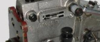
Characteristics of the fuel injection pump MTZ-80 of the D-240 UTN-5 engine
| High pressure fuel pump - injection pump of the MTZ tractor | |
| Catalog number | 4UTNI-1111005-20 |
| Application | MTZ series tractors |
| Engine | D-240, D-241, D-242, D-243, D-244, D-248, D-248.1, D-247.1 |
| Peculiarities | UTN, in-line |
| Drive type: injection pump | splined bushing |
| Factory | Noginsk |
| Analogs | PP4M9P1g-4201 (MOTORPAL, Czech Republic) |
Injection pump device MTZ 80 Belarus
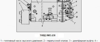
Diagram of the fuel pump UTN 5 diesel D-240
: 1 - housing; 2 - discharge valve; 3 - plunger pair; 4 - plunger; 5 — pusher bolt; 6 - cam shaft; 7 — splined bushing; 8 - mounting flange; 9 — booster pump; 10 — manual pump; 11 — air release plug; 12 - bypass valve; 13 — earring; 14 — regulator spring; 15 — corrector; 16 — breather; 17 — nominal bolt; 18 — regulator body; 19 — drain plug; 20 — control hole plug; 21 - plate; 22 — drain plug; 23 — bolt of maximum rotation speed; 24 — control lever; 25 — gear rack; 26 — ring gear; 27 - tightening screw.
1 - pressure fitting;
2 - clamps; 3 - spring; 4 - discharge valve; 5 — valve seat; 6 - gasket; 7 — plunger bushing; 8 - plunger pair; 9 - plug; 10 — ring gear; 11 — rotary sleeve; 12 — regulator cover; 13 — rack rod; 14 — spring lever; 15 — regulator spring; 16 — enrichment spring; 17 — main lever; 18 — corrector housing; 19 — corrector rod; 20 — adjusting screw; 21 - intermediate lever; 22 — nominal bolt; 23 - bolt; 24 — regulator body; 25 — load axis; 26 - heel; 27 - coupling; 28 — heel axis; 29 — lever axis; 30 — regulator weights; 31 — thrust ball bearings; 32 — drain plug; 33 — cargo hub; 34 — shock absorber block; 35 — washer; 36 — bearing cup; 37 — oil deflector; 38 — control lever; 39 - cam shaft; 40 - plug; 41 — eccentric drive of the booster pump; 42 — flange for mounting the booster pump; 43 — adjusting washer; 44 — mounting plate; 45 — pump housing; 46 — oil supply hole; 47 — roller nut; 48 — splined bushing; 49 — mounting flange; 50 — pusher with roller; 51 — pusher adjusting bolt; 52 — spring plate (lower); 53 — plunger spring; 54 — spring plate; 55 — rack; 56 — bolt for bleeding; 57 — channel for fuel removal; 58 — bypass tube; 59 — bypass valve body; 60 - plug; 61 — valve ball; 62 — hole for fuel supply; 63 — channel for fuel supply; 64 - cut-off hole; 65 — inlet hole of the plunger sleeve; 66 - pin; 67 — hatch cover; 68 — adjusting screw; 69 — gasket; 70 - filler plug; 71 — adjusting screw; 72 — corrector spring; 73 - tightening screw. The injection pump consists of the following main components: plunger pairs, housings, discharge valve, pushers, cam shaft, plunger drive mechanism. The fuel pump head and its housing are one piece and made of aluminum alloy. Principle of operation
A cast iron plate is attached to the front of the housing for mounting the pump on the engine, and at the rear there is a flange for mounting the regulator. All four sections of the pump are a miniature fuel pump, whose operating principle is as follows. As the cam shaft rotates, the cam protrusion runs up against the roller at a certain period of time and lifts the tappet. After the cam protrusion comes out from under the roller, the springs lower the pusher. Simultaneously with the pusher, the plunger rises and falls, thus producing a reciprocating movement in the cavity of the sleeve. As the plunger moves downward, fuel fills the space it vacated in the sleeve. During its upward movement, the plunger compresses the fuel and the pressure created opens the discharge valve, providing a path for the fuel to reach the injector. The cycle of suction and discharge is then repeated. The plunger rotation mechanism, which serves to change the fuel supply, consists of a rack and gear rims. The plunger bushings have rotary sleeves equipped with toothed rims. With its protrusions, the plunger fits into two longitudinal grooves of the rotary sleeve. A plunger spring is placed on the sleeve. Through the lower plate it rests against the pusher bolt, and through the upper plate it rests against the pump housing. The toothed rims of the sleeve are in constant engagement with the teeth of the rack, which moves in two bronze bushings. Using a rod, the rack is connected to the regulator levers and moves under their influence, turning the gear ring simultaneously with the plunger sleeve and thus changing the fuel supply. Tangential profile cams are placed on the cam shaft symmetrically to each other. Between the second and third cams there is an eccentric that drives the fuel boost pump. At the top of the rear part of the fuel pump housing of the MTZ 82 tractor there is a bypass valve through which excess fuel supplied by the fuel priming pump is returned to its suction chamber. Thus, the pressure in the channels of the D-240 diesel injection pump head is maintained in the range of 0.07-0.12 MPa (0.7-1.2 kgf/cm2). The pushers slide into holes in the horizontal partition of the fuel pump block. There is a hatch on the side wall of the housing, through which it regulates the uniformity of fuel supply across sections and, in fact, the fuel supply itself. A threaded hole is used to control the oil level in the pump housing. To communicate the internal cavity of the fuel pump housing with the atmosphere, a breather is used, equipped with an air purification filter made of elastic foam.
Operation and functions of power system components
The power supply system of the MTZ 80 tractor includes a set of interacting components that provide fuel filtration, supplying it under pressure with subsequent spraying in the combustion chambers, as well as components that ensure the filling of the cylinders with air during mixture formation and the subsequent removal of exhaust gases.
MTZ 80(82) fuel system diagram
Fuel tank MTZ 80(82)
It consists of two tanks located under the tractor cabin, the volume of which provides a fuel supply of 120 liters (in new tractors 130 liters). In the upper inner side parts, the tanks are connected to each other by an overflow pipe and a pipeline that combines the tanks into a single volume. The left tank is equipped with a filler neck with a filter mesh and a cap, as well as a fitting for receiving excess fuel coming from the injectors, which tractor drivers call “return”. At the bottom of the tanks there is a fitting for connecting to the supply pipeline and a plug for draining fuel and removing sediment. The right tank is equipped with a fuel level sensor. The tanks are attached to the rear axle housing with tightening straps.
Fuel tanks MTZ 80
Fuel equipment pipelines
The system components are connected by high and low pressure fuel lines. The fuel supplied from the tank through the coarse and fine filtration system using a booster pump to the high pressure pump passes through low pressure pipelines with a large cross-section.
High pressure pipelines
Thick-walled, seamless, high-pressure steel pipelines supply fuel from the working sections of the pump directly to the nozzles and have a thinner cross-section. To ensure a tight connection, the ends of the tubes are equipped with welded ball ends, which are attracted by union nuts to the cone fittings of the system components. The supply pipelines coming from the pump sections have individual lengths and bend shapes for easy installation.
High pressure fuel line
Coarse and fine filters
The coarse settling filter receives fuel from the tank, cleans it from large mechanical impurities and is connected through the high-pressure fuel injection pump to the fine filter. After final filtration, the fuel is sent to the system pump through a pipeline connected to a fitting in the head of the unit.
Coarse fuel filter MTZ 80
The coarse cleaning device is located on the right side of the engine above the neck for filling oil into the crankcase and is attached to the block with a bracket with two bolts. The filter mesh element of the unit retains clogging with a diameter above 0.45 mm. At the bottom of the glass there is a tap for periodic drainage of clogged sludge.
Fine filter MTZ 80
The fine filter is attached with a bracket to the cylinder head on the left side of the diesel engine above the injection pump regulator. The unit is equipped with a lower plug for draining sludge and a valve for removing air when the system is filled with fuel. The paper filter elements, which are replaced when dirty, remove particles larger than 0.00145 mm, which corresponds to the clearance in the operation of precision pairs of pump plungers.
Failure to promptly wash sediment tanks and filters, as well as replace filter elements, prevents the passage of fuel and leads to a general decrease in the performance of the fuel injection pump. The entry of dirty fuel into the system leads to malfunctions, wear of precision pairs and premature reduction of pump life.
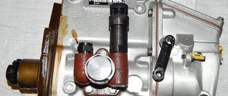
Fuel pump with booster pump
The MTZ 80(82) tractor is equipped with four sectional high-pressure pumps of type 4 UTN and 4UTNM (early version UTN-5) with a mechanical all-mode regulator. The injection pump of the system is the main functional unit, which creates a working pressure for injection of over 30 MPa (300 kgf/cm²) with fuel supplied to the injectors synchronously with the compression strokes of the diesel cylinders. The unit is located on the left side of the engine and is driven by the timing gear. The pressure is created by the reciprocating movement of plunger pairs of sections of the assembly, the drive of which is carried out by rotation of the cam shaft through pushers. Automatic control of the fuel supply in accordance with the operating modes of the diesel engine is carried out by a centrifugal-type mechanical device, the housing of which is attached to the rear wall of the pump. To lubricate the injection pump mechanism, the unit housing is filled with engine oil.
Pump design UTN 5
The booster pump, which provides pressure potential to overcome resistance when fuel passes through the system filters, is mounted on the injection pump housing and is also driven by the pump shaft. Additionally, the pump is equipped with a manual fuel pump. The device is used to fill the system with fuel or remove air pockets. Injection is carried out by manual translational movement of the rod.
Problems with a node can be of four types:
1 Malfunction of pump sections
Reduced overall pump performance and pressure drop as a result of wear of plunger pairs and discharge valves. Characterized by a general drop in power and incomplete combustion of fuel. When a plunger pair fails or gets jammed in a pump section, it is accompanied by unbalanced engine operation and a drop in power. Lack of uniformity of fuel supply by sections as a result of incorrect settings of the plunger performance also affects the diesel power. Wear of the shaft support bearings and the appearance of increased axial clearances on the shaft also affect the stability of the fuel supply to the pump sections.
2 Malfunction of the regulator
Incorrect adjustment of the regulator causes inadequate fuel supply in various operating modes, which can result in poor engine starting, excessive fuel consumption, and insufficient power development under load.
3 Incorrect pump installation and drive failure
The appearance of play in the meshing of the pump drive gears and the splined coupling with the adjusting washer provokes engine operation with characteristic jumping instability of speed at the same fuel supply. The effect of instability appears due to the changing angle of fuel supply as a result of increased play in the engagement of pump drive parts.
4 Wear of the precision boost pump pair
The problem leads to a drop in pressure in the low-pressure pipelines of the system, which makes it difficult for fuel to pass through the filters, reducing the performance of the injection pump. Also, when the pump parts wear out, fuel begins to enter the pump body, which accelerates the wear of the assembly mechanism.
Spray nozzles
Fuel is supplied to each diesel cylinder by a spray nozzle, the task of which, for good ignition and complete combustion, is to atomize the fuel to a foggy state. The MTZ 80(82) tractor engines use FD-22 type injectors with four-hole nozzles. In early versions of the tractor model, the spray pressure in the nozzles is 17.5 MPa; in modern versions, the operation of the nozzles is adjusted to a pressure of 21.6-22.4 MPa.
Injector MTZ 80
The operating principle of the device is to pass fuel between the needle cone and the nozzle seat. The spray actuation pressure is regulated by a spring, which creates a force to press the needle. When the atomization pressure is reached, the fuel moves the needle, overcoming the force of the spring and passing through the resulting gap, it is sprayed. After the pressure drops, the spring presses the needle against the seat, stopping spraying. Excess fuel after spraying is discharged back into the tank through a pipeline connecting all nozzles.
Poor atomization or its absence as a result of incorrect adjustment or malfunction of the injector leads to unstable engine operation, incomplete combustion of fuel and, as a result, a drop in power.
Air filter
Air filter MTZ 80
The unit provides combined air purification from dust entering for mixture formation in the combustion chambers of the engine. Filtration is carried out by a mesh element and an oil bath that traps solid particles in the incoming air. The mesh compartment of the unit has a stepped structure and is composed of three elements with different degrees of throughput of solid particles. The efficiency of the unit is maintained by periodically washing the housing and filter elements and changing the oil in the dust catcher.
An increase in filter clogging leads to a drop in engine power as a result of insufficient air during mixture formation. The penetration of contaminated air into the gas distribution mechanism of a diesel engine leads to the formation of abrasive deposits on the valves and in the combustion chambers, which reduces the overall service life of the engine.
Suction manifold and air preheater
Purified air is supplied to the intake valves in the cylinder head through the branches of the suction manifold. The cast part is secured by tightening the threaded rods; the joint tightness is ensured by heat-resistant paranitic gaskets in the joints.
Intake manifold MTZ 80
The manifold is equipped with a controlled damper to shut off the air supply if necessary to turn off the engine. The damper control cable is routed into the tractor cab.
Manifold pipe with damper
To facilitate starting in the cold season, the intake manifold is additionally equipped with an electric torch air heater. The device is installed with a special collector window. The principle of operation is to heat the incoming air by burning diesel fuel. Ignition is carried out by a filament coil while holding the starter key in the first position. Fuel is supplied through a separate pipeline coming from the fine filter with the simultaneous opening of the device bypass valve when the spiral is heated.
Electric torch heater for engine D 240
Exhaust manifold and exhaust pipe
The cast iron outlet manifold receives exhaust gases from the exhaust valves of the gas distribution mechanism and leads them to the exhaust pipe. The part is also attached to the tractor cylinder head by tightening the studs. The milled contact surfaces of the units are sealed with heat-resistant gaskets.
Exhaust manifold MTZ 80
The tractor exhaust pipe serves as a silencer for engine noise and as a spark arrestor in the exhaust gases.
An additional component in the power system can be a turbocharger to force air into the diesel cylinders. By operating a node in the system, an additional increase in power is achieved. At the same time, engine operation is characterized by an increase in thermal and mechanical loads on the parts of the cylinder-piston group and the crank mechanism.
Plunger pair
The plunger pair consists of a bushing and a plunger, which are the main working parts of the fuel pump. Thanks to it, the required amount of fuel is supplied to the engine cylinders under high pressure. The plunger and bushing are made of alloy steel, after which they are heat treated and form a precision pair. This design was implemented because during operation high pressure is generated in the pump, as a result of which tightness and vapor density are required to block the flow of fuel from the space above the plunger. The plunger pair cannot be disassembled and if one of the parts fails, the entire pair is replaced. The upper part of the plunger pair bushing has a significant thickening, since in this place it is exposed to serious pressure. The upper thickened part of the bushing has an end in the form of a step to allow it to fit into the socket of the pump housing. There are two windows in the upper part of the sleeve: bypass and suction. Fuel is cut off and bypassed through the bypass window, and fuel is supplied to the space above the plunger through the suction port. These holes are connected in the upper part of the injection pump with longitudinal channels. The bushing is secured against rotation by a pin that fits into the milled groove of the bushing. The falling out of the pins is blocked by the hatch cover. The bushing is located on top of the pump housing, and the discharge valve is pressed to its upper end. To ensure the required tightness, the contacting ends of the injection valve seat and bushings have a well-ground surface. Diagram of a plunger pair
: 1 - fitting; 2 — pressure valve spring stop; 3 — discharge valve spring; 4 — discharge valve seat; 5 - discharge valve; 6 - seal; 7 - bushing; 8 - plunger; 9 - rack; 10 — ring gear; 11 — rotary sleeve; 12 — upper plate of the plunger spring; 13 — plunger spring; 14 — lower plate of the plunger spring; 15 — coupling screw; 16 and 17 - suction and bypass windows. The plunger looks like a cylindrical rod, on the surface of which there is a pair of symmetrically placed spiral grooves, one of which is carefully processed and is designed to change the volume of fuel injected into the cylinder of the D-240 engine. When the edge of the bypass window of the bushing coincides with the edge of the groove, the pressure in the space above the plunger decreases sharply, and therefore the fuel supply to the injector stops. Another groove equalizes the specific fuel pressure acting on the side surface of the plunger during pump operation. On the plunger, below the cut-off edge, there is an annular groove where leaked fuel is retained, which is then used to lubricate the plunger pair. At the bottom of the plunger there are two protrusions to control its rotation and a head on which the spring plate rests.
Exhaust gases are removed from the cylinder through the exhaust manifold and released into the atmosphere through the muffler.
Fuel that has leaked through the gaps between the needle and the nozzle body is discharged from the injectors into the fuel tank through a tube.
The power supply system of the SMD-60 engine (T-150 tractor) works in the same way, which differs only in the design of individual components and assemblies (fuel pump, fine filters, regulator).
Air cleaning. A diesel engine, depending on its power, consumes from 5 to 30 kg of fuel per hour. The combustion of 1 kg of fuel requires 18–20 kg of air. Consequently, the engine consumes up to 4-5 tons of air per shift. The dust content in the air ranges from 0.05 to 2.0 g per 1 m3, and it has been established that 1 g of dust entering an engine cylinder increases cylinder wear by 0.01 mm and causes a drop in power by 0.5%. Therefore, it is necessary to protect the engine cylinders from dust and extend the service life of the piston group parts. Air purifiers perform this role.
Rice. 1. Power system diagram: 1 - muffler; 2 — fuel tank; 3 - coarse filter; 4 - booster pump; 5 - fuel pump; 6 - regulator; 7 — fine filter; 8 — air cleaner; 9 — intake manifold; 10 — electric torch heater; 11 - drain pipeline; 12 — nozzle; 13 - combustion chamber; 14 — exhaust manifold
According to the cleaning method, air purifiers are divided into inertial, filtering and combined. Combined purifiers use dry and wet inertial and filter cleaning methods, and therefore they are most widespread.
An air purifier of this type (diesel D-240) is shown in Fig. 2, a. Air purification in it occurs as follows.
During the intake stroke, a vacuum is created in the cylinder by the piston moving towards BDC. As a result of this rarefaction, air is sucked in from the atmosphere and enters through a mesh into a dry centrifugal cleaner installed on the central pipe, and, passing through the swirler blades, acquires a rotational motion. Under the influence of centrifugal forces, dust particles are thrown towards the walls of the hood and released into the atmosphere through the cracks.
Dry inertial cleaning separates up to 50-60% of dust entering the air.
Next, the air enters the central pipe, at the exit from it, in the lower part, it hits the oil in the cup of the removable air cleaner pan and, abruptly changing direction, goes up inside the housing. At this moment, the air leaving the central pipe undergoes a second cleaning - wet inertial, since heavier particles are separated from the air when it changes the direction of movement and are trapped in the oil.
The air, having captured oil particles from the sump, passes through the wet filter elements in the housing, undergoing a third cleaning from the smallest particles. Oil and dust particles remain on the nylon filter packing and gradually flow into the air cleaner pan, cleaning the filters. Purified air enters the engine cylinders through pipe 3 and the intake pipe.
The D-50, D-37E, D-21, AM-41 engines have a similar air cleaner design.
The SMD-14 diesel engine is equipped with a combined cyclonic air cleaner with two cleaning stages. The first stage is a dry cyclone cleaner with ejector removal of dust by exhaust gases, the second stage consists of filter cassettes 22 made of wire knitted mesh, moistened with oil.
Rice. 2. Combined diesel air cleaners D-240 and SMD-14: a — diesel air cleaner D-240; b — diesel air cleaner SMD-14; 1 - body; 2 — support holder; 3 — side pipe; 4 - head; 5 - central pipe; 6 - pipe; 7 - separator; 8 — swirler; 9 — cap; 10 - cracks; 11 — hairpin; 12— mesh; 13 - clamp; 14, 15 — filter elements; 16 — clip clamp; 17 — lock holder; 18 — sealing ring; 19—tray, 20—cup; 21 — air intake pipe; 22 — cassettes; 23 — casing; 24 — cyclone; 25 — dust suction tube; 25 — bunker; 27 — spark arrester impeller; 28 — spark arrester; 29 — ejector
This air purifier works as follows. Air enters the inlet pipes of the cyclones through the mesh and intake pipe. Since the inlet pipe is located tangentially to the inner surface of the cyclone, the air entering the cyclone acquires a rotational motion. Under the influence of centrifugal forces, the dust that gets into the cyclone is thrown back to its walls and, together with the air, falls down to the middle of the cyclone, where the air changes direction along the inner tube of the cyclone and flows upward to the filter cassettes.
Passing cassettes moistened with oil, the air is cleaned of the smallest dust particles and enters the engine suction pipe.
The dust particles are lowered through the cyclone into the bunker. As a result of the vacuum created by the exhaust gases in the ejector suction tube, dust from the dust bin is sucked out and released along with the exhaust gases into the atmosphere.
Similar air cleaners are installed on AM-01M, SMD-60, SMD-62, YAME-238NB, YaMZ-240B engines; they differ only in size, number of cyclones and number of filter cassettes.
Air purifier maintenance. The following maintenance operations are carried out behind the inertia-oil air cleaner: - clean the dust removal slots of the air cleaner hood after 60 hours of operation during maintenance No. 1 (TO-1); - change the oil in the air cleaner pan after 20-30 hours when working in dusty conditions, after 60 hours - under normal conditions, and 480 hours - when working in winter conditions. Do not allow the pan to overflow with oil above the established level (ring band); - periodically check the tightness of the connection of the air cleaner and the intake manifold to the engine. To do this, remove the air cleaner cap and, when operating at medium engine speeds, tightly close the central pipe of the air cleaner, and the engine should stall. Otherwise, the tightness is broken and it is necessary to eliminate air leaks in addition to the air cleaner; — after 240-480 hours (TO-2), depending on operating conditions, disassemble the air cleaner, clean the first cleaning, wash the body, central pipe, filter cartridges and replace the oil.
Maintenance of the cyclone air cleaner comes down to washing the Cassettes after 60 hours of operation in dusty conditions and after 240 hours in normal conditions, as well as checking the tightness of the air cleaner connection and tightening the fastening of the dust suction tube hoses. After washing, the cassettes are soaked in oil, the oil is allowed to drain from them and the cassettes are put in place.
Do not work with the dust extraction tube removed from the air cleaner.
Fuel for diesel engines, fuel tanks. Diesel fuel is used as fuel in diesel engines, while gasoline is used in starting engines.
Diesel fuel is used in agriculture in two grades - winter and summer.
Each grade is available with different sulfur content. Fuel obtained from low-sulfur oil and having a low sulfur content is marked with two letters “DL” - summer and “DZ” - winter, and from sour oil with a sulfur content in the fuel from 0.4 to 1% is marked with one letter “3” - winter or “L” - summer fuel.
The following grades of gasoline are used: A-66, A-72, A-76, AI-93. AI-93 gasoline is mainly used for passenger cars: Moskvich, Zhiguli.
The fuel should not contain mechanical impurities or water, and therefore, before filling into tractor tanks, diesel fuel is preliminarily settled in containers for 48 hours.
Fuel tanks. On diesel tractors starting from a starter, a tank for diesel fuel is installed, and when starting from a starting engine, in addition to the main tank, a tank for gasoline is installed. Some tractors (MTZ-80, K-701) have two main tanks. The capacity of the tanks ensures that the engine can operate at full load for at least 10 hours. The fuel tank is made of sheet steel and has a filler neck with a mesh filter in the upper part. The lid covering the neck has a hole for communicating the tank with the atmosphere and a filter. At the bottom of the tank there is a flow valve that shuts off the fuel outlet from the tank, and a drain valve to drain the sediment.
Maintenance of the tank comes down to cleaning the tank from dust and dirt, cleaning the hole for air passage in the neck cover. After 60 hours of operation, the sediment is drained from the tank, and after 960 hours (TO-3), the tank and filler cap are washed.
Fuel cleaning. Coarse and fine fuel filters.
The duration and uninterrupted operation of the fuel pump and injectors depends on the degree of fuel purity. Therefore, diesel fuel is purified in coarse and fine filters.
Coarse filters are designed to remove mechanical impurities and water from fuel. They are installed between the tank and the booster pump. Modern diesel engines use mesh, plate and belt-slot coarse filters.
In slot-plate filters, fuel is cleaned by passing through the slots formed between two adjacent disks by an asterisk. Having passed between the disks, the fuel enters the oval hole in the disks and is directed through the channel to the booster pump.
In slotted belt filters, the 0.09 mm thick slots are formed by protrusions stamped on a tape wound around a corrugated cylinder.
The most widely used (on engines D-21 A, D-240, AM-41, SMD-60, A-01M) are unified filter-settlers FG-1 and FG-2 (differing in size). The fuel sucked from the tank by the pump is supplied through the fitting and the distributor holes into the internal cavity of the glass. The bulk of the fuel, abruptly changing direction, passes through the mesh of the filter element and the central hole and is sucked into the booster pump. Mechanical particles and drops of water, which have a large specific gravity, continue to move downwards by inertia along the walls of the glass and fall into the settling zone under the damper; the accumulated residues are periodically drained through a hole closed with a stopper.
Maintaining the coarse filter. After 240 hours (TO-2), the sediment is drained from the filter. Wash the filter after 960 hours of operation (TO-3). When washing the filter element, do not clean the mesh with wooden or metal scrapers.
On K-701 tractors, the cleaning filter is a mesh frame with a fleecy cotton cord wound around it. Its maintenance is reduced to replacing the filter element after 240 hours of operation.
Fine filters clean fuel from the smallest mechanical particles. Tractor diesel engines use filters with cotton filter elements (D-65N, D-50, D-37M engines) and the most widely used ones with paper filter elements (A-01M, SMD-60, SMD-62, D-240, D engines -21 A). These filters provide high quality fuel purification, are more durable and can be washed with reverse fuel flow without disassembling the filters or stopping the engine. In Fig. Figure 4 shows a two-stage fine filter for SMD-60 and A-01M engines with the first and second cleaning stages connected in series.
Rice. 3. Coarse fuel filters:
Rice. 4. Fine fuel filter 2TF-3: 1 - three-way valve; 2 - bypass valve; 3—valve; 4, 7 — coupling nuts; 5 — filter bracket cover; 6 — filter bracket housing; 8 — filter cover; 9 - gasket; 10, 18 — seals; 11 — body; 12 — filter element; 13 — coupling bolt; 14, 19 — fittings for flushing; 15 - nut; 16 — drain tube; 17 - spring
The first stage of cleaning is a 2TF-3 filter, consisting of two sections. Each section is a plastic housing attached to a cover 8. Inside the housing there is a non-separable paper filter element 12 of the EFT-3 type. The second stage of cleaning is the TF-3 filter with one EFT-3 filter element.
The filter element is a curtain made of special paper placed in a cardboard cylinder with holes for the passage of fuel. The curtain is rolled into a cylinder (“accordion”), which increases the cleaning surface. The cylinder is tightly closed at the bottom and top with tin lids. The element is put on the rod, sealed at the top with a felt ring, and at the bottom with a rubber seal, and pressed against the lid with a spring.
At the bottom of the housing there are plugs for draining sediment. The lid contains a three-way valve for washing sections. A valve with a drain tube is screwed into the cover of the TF-3 filter of the first stage to remove air from the power system. (For the A-01M engine, the valve is installed on the second stage filter cover).
Fuel, pumped by the booster pump through a tube and a three-way valve, enters the filter housing. Both filter elements operate in parallel. The fuel passes through the curtain of the paper filter element into the internal cavity, is cleaned, and mechanical impurities are deposited on the outer surface of the curtain. From the internal cavity of the element, fuel flows through a channel in the cover into the tube, and then into the TF-3 filter, which works in a similar way. The purified fuel is sent through the tube to the fuel pump.
On the MTZ-80 and MTZ-82 tractors (D-240 engine), the fine filter has three replaceable paper filter elements of the BFDT type (a design similar to the EFT-3 element), placed in one housing.
On the K-701 tractor, replaceable filter elements are installed in two fine fuel filter housings. Each element is a perforated metal frame with a filter mass - wood flour on a pulverbakelite base.
Maintenance of the fine filter. Filters 2TF-3 and 2STF-3, having paper elements ETF-3 (tractors DT-75M, T-150, T-150K, T-4M), are washed with a reverse flow of fuel after 240 hours of operation at TO-2. To do this, the engine is given maximum idle speed; By turning the switch tap 90° to the position “Flushing the right section” and unscrewing the fitting a few turns, flush until a light stream of fuel appears. Then wash the left section by turning the tap to the appropriate position and unscrewing the fitting. The filter tap 2STF-3 of the DT-75M tractor has two positions: “Work” and “Flush”.
ETF-3 filter elements are replaced after E60–1500 hours of engine operation, depending on the purity of the fuel used.
Maintenance of the BFDT paper filters of the MTZ-80, MTZ-82 tractors comes down to periodically draining the sludge after 240 hours of operation and changing the filter elements (with washing the housing) after 1500 hours of operation. On the T-25A tractor and T-16M self-propelled chassis, fine paper filters are changed after 960 hours of operation.
Cotton elements of fine filters for tractors MTZ-50, YuMZ-6L, T-40M are changed after 960 hours of operation.
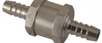
Diesel booster pumps are used to overcome the resistance of fuel filters when supplying fuel to the fuel pump.
Booster pumps can be piston, gear, or diaphragm. On tractor diesel engines, piston booster pumps are most widely used (engines D-37E, D-65N, D-240, SMD-14, AM-41, SMD-60, A-01M, YaMZ-240B). A diagram of the design and operation of a piston-type booster is shown in Fig. 18.
The pump works as follows. When the fuel pump camshaft rotates, the shaft eccentric runs against the pusher roller, moving the pusher and piston forward, while the spring is compressed. As a result, pressure is created above the piston in cavity A, and a vacuum is created under the piston in cavity B. As a result, the inlet valve will close, and the bypass valve will open, and fuel from the cavity will flow through the channel into cavity B.
When the pusher leaves the eccentric, the piston, under the action of a compressed spring, will move backward, creating pressure in cavity B and vacuum in cavity A.
Under the pressure of the piston, fuel from cavity B is pumped through the channel and fuel line into the fine filter, since the bypass valve will close at this moment. At the same time, under the influence of vacuum in cavity A, the inlet valve will open and fuel from the coarse filter will be sucked into cavity A.
Then the fuel supply process is repeated.
The pump's performance changes automatically depending on the load, engine speed and the degree of filter contamination. For example, with a decrease in load, fuel consumption decreases, as a result, the pressure in cavity B increases and may be higher than the spring pressure (1.5-1.7 kgf/cm2), then the piston will stop moving backward or reduce its stroke, that is, the pump or completely turns off or reduces its performance.
Removing air from the power system. The entry of air into the fuel system causes a disruption in the fuel supply to the cylinders, unclear engine operation, and makes it difficult to start the engine. To remove air trapped in the system, a manual pump is installed on the body of the mechanical pump.
Rice. 5. Piston-type booster pump: a, b - sections of the pump; c, d - pump operation diagrams; 1 - body; 2 - piston; 3 — piston spring; 4— plug; 5 - rod; b — pusher spring; 7 — pusher; 8 - axis; 9 — roller; 10, 22 — fuel lines; 11 - bypass valve; 12 — valve spring; 13 — valve plug: 14 — inlet valve; 15 - cylinder; 16 - cover; 17 — handle; 18 — rod; 19 — hand pump piston; 20 - sealing ring; 21 - gasket; 23, 25 — channels; 24 - fuel pump camshaft
The pumping process is carried out as follows. Unscrew the handle of the hand pump piston rod and move it up and down.
When the handle is moved up, fuel is sucked into the pump; when moved down, fuel is pumped into the fine filter. To remove air, open the valve on the filter and pump fuel until fuel comes out of the drain tube without air bubbles. Then close the valve and screw the rod handle onto the pump housing cover.
On the K-701 tractor, to fill the system with fuel and remove air from it, a manual fuel priming pump RNM-1k of a diaphragm type is installed in the tractor cabin.
The fuel pump serves to supply under pressure to the injectors at strictly defined moments a precisely measured portion of fuel corresponding to the engine load. Modern tractor diesel engines use two types of pumps: multi-plunger (in-line) and single-plunger distribution type. The number of pump sections of a multi-plunger pump corresponds to the number of engine cylinders, and each section is connected to an injector of one cylinder.
In a single-plunger distribution-type pump (engines SMD-60, SMD-62, D-21A), one pump element supplies fuel to several cylinders, alternately connecting to the corresponding injectors.
Let's consider the design and principle of operation of a four-plunger fuel pump.
The UTN-5 fuel pump is a basic model of small-sized pumps with 2, 3, 4 and 6 pump elements. They are installed on D-65N, D-50, D-240, D-37E engines. The pump is mounted in one unit with an all-mode centrifugal regulator and a booster pump.
The fuel pump consists of the following main elements: a housing in which four pumping elements are located, a plunger drive mechanism and a mechanism for regulating the amount of fuel. The main parts of the pumping element are a plunger with a bushing. Above the bushing, installed in the vertical hole of the housing, there is a discharge valve seat with a gasket and a discharge valve. The valve is closed by a spring. All of the above parts are secured with a fitting to which a high-pressure pipeline leading to the nozzle is connected. The plunger drive mechanism consists of a cam shaft, a pusher, and springs with plates.
The mechanism for regulating the amount of fuel consists of a rack, a gear and a rotary sleeve. The ring gear is mounted on a rotary sleeve and secured with a coupling bolt. The plunger shank fits into the lower cutout of the sleeve with its protrusions. When the rack moves, the gear rim rotates the sleeve, and with it the plunger.
In the upper part of the head housing (for 4TN-8, 5X10 fuel pumps, the head and housing are made separately) there are two channels: fuel supply and outlet, connected to each other by drilling. A fuel supply tube from the fine filter is attached to the fuel supply channel. A bypass valve is installed at the outlet of the outlet channel, which serves to bypass excess fuel through the drain tube into the booster pump. The valve is adjusted to maintain an excess pressure of 0.7-1.2 kgf/cm2 in the channels.
The plunger sleeve has two diametrically located holes: inlet and outlet. When installing the bushing into the housing hole, the inlet hole (upper) communicates with the fuel supply channel, and the bypass hole communicates with the fuel outlet channel.
Through the inlet port, fuel from the channel enters the space above the plunger, and through the bypass port, the cutoff (end of supply) and bypass of the fuel into the outlet channel are carried out.
The plunger is a cylindrical rod, on the surface of which two symmetrically located spiral grooves are made, one of them serves to change the amount of fuel, and the other groove helps to equalize the specific pressure on the side surface of the plunger during pump operation. The plunger has axial and radial holes connecting the spiral groove with the space above the plunger.
The plunger has an annular groove to lubricate it with leaked fuel. At the bottom, the plunger has two protrusions that fit into the rotary sleeve, and a shank for connecting to the lower spring plate.
Pump operation. When the shaft cam does not press on the pusher, the plunger moves down under the action of a spring, the inlet hole of the sleeve opens and fuel from the supply channel fills the space above the plunger.
Rice. 6. Operation diagram of the fuel pump section: I - bypass window; II — inlet window; A. b, c, d. d, b,, c, - plunger positions
When the shaft cam begins to lift the pusher and plunger, some of the fuel is forced out by the plunger into the supply channel. This continues until the end of the plunger closes the inlet hole of the sleeve. As the plunger moves further upward, it presses against the fuel located in the closed space above the plunger, and this pressure opens the discharge valve. Valve belt B comes out of the seat and fuel flows from the space above the plunger into the high-pressure pipe. Fuel pressure is transmitted to the injector, the needle in it rises and fuel injection begins into the engine cylinder.
Fuel injection continues until the cut-off edge E of the spiral groove of the plunger is aligned with the bypass hole of the plunger; fuel is cut off. From this moment, fuel from the space above the plunger through the central B and radial holes D and the screw groove flows through the bypass hole into the outlet channel of the head, the discharge valve closes under the action of a spring and the supply stops, despite the fact that the plunger moves upward.
The stroke of the plunger during pump operation remains constant, and the amount of fuel supplied by the pump per cycle can change and is determined by the active working stroke of the plunger A. When the plunger is turned to the right, the distance A will decrease to A and that is, the cutoff will occur earlier, the fuel supply to the cylinder will decrease, the amount of fuel transferred into the outlet channel will increase. By further turning the plunger to the right, you can completely stop the flow.
The rotation of the plungers is carried out by moving the rack. If the rack moves forward (from the regulator), the feed in all sections increases, and if backwards, the feed decreases or is completely turned off.
The uniformity of fuel supply in each individual section is regulated by turning the sleeve with the plunger relative to the gear rim, for which the tightening screw is loosened and, holding the rim, turn the sleeve with the plunger in one direction or another, decreasing or increasing the flow.
The operating principle of multi-plunger pumps for engines AM-41, YaMZ-240B, A-01M, SMD-14 is similar to the UTN-5 pump described above, and they differ in size, number of sections and some design features.
The fuel distribution pump ND-21 is a basic model of a unified type of pump designed for installation on two-cylinder pump engines - ND-21/2 (D-21A engine), four-cylinder - ND-21/4 (D-37E) and six-cylinder - ND -22/6B-4 (SMD-60, SMD-62, SMD-64).
In these pumps, fuel is supplied to two, three or four cylinders using one plunger, while the plunger not only reciprocates, but also rotates around its axis, supplying fuel alternately to the tubes of each injector.
The ND-22/6B-4 pump consists of a one-piece aluminum housing, divided into three cavities: a pump chamber, in which two high-pressure sections with a pusher are located; regulatory, where the regulator parts are installed; the lower one, which houses the cam shaft, the drive gear of the regulator and plungers, and the eccentric shaft. A booster pump is attached to the side of the housing and is driven by an eccentric shaft.
The cam shaft rotates in ball bearings and has two triangular cams (the ND-21/4 pump has tetrahedral cams), above which roller tappets are located. For one revolution of the cam shaft, the section plunger makes three double strokes (up, down) and one revolution around its axis, supplying fuel to three cylinders with each section.
The rotation of the plunger is carried out by a toothed sleeve, which meshes with an intermediate gear, which receives rotation from a ring gear mounted on the regulator shaft. The latter is driven from the cam shaft through a pair of bevel gears.
The high pressure pump section is shown in Fig. 7, b. The main parts of the pump section: plunger with bushing, head (on the latest designs the bushing and head are made one-piece), dispenser, toothed bushing, spring with plates.
The plunger has a central hole and two radial ones: an upper distribution hole d with a recess and a lower shut-off hole c. The central hole d serves to supply fuel from the above-plunger cavity to the distribution hole d and shut-off hole c. The distribution hole can be combined with the distribution channel of the head e, above which a check valve 12 with a spring, a discharge valve seat, a discharge valve with a spring and a stop are installed. High pressure fittings are screwed into the head from above. Rubber rings create a tight seal between the fuel and oil chambers of the pump.
Pump operation. When the cam shaft protrusion does not press on the pusher, the plunger rotates and lowers under the action of a spring. Fuel from the suction cavity through channels a enters the space above the plunger (suction stroke). Under the action of the cam and the pusher, the plunger moves upward and part of the fuel is forced back into the suction cavity. With further upward movement, the plunger closes the inlet holes and creates pressure in the space above the plunger. At this moment, the distribution groove of the rotating plunger coincides with the channel in the sleeve and fuel from the space above the plunger enters through the central hole of the plunger, the distribution groove into the distribution channel of the head and through the discharge valve is supplied through the fuel line to the nozzle, while the dispenser 5 tightly closes the shut-off hole of the plunger.
Fuel supply will continue until the shut-off holes of the plunger exit the dispenser. At this moment, a cutoff occurs and the valve lowers.
The amount of fuel supplied by the pump is regulated by the movement of the dispenser along the plunger: the higher the dispenser, the larger the portion of fuel supplied to the injectors, because the cutoff will occur later, and the greater the working stroke of the plunger.
The highest flow corresponds to the uppermost position of the dispenser. In the lowest position of the dispenser, there is no supply, since along with closing the outlet holes with the plunger, at the same time, the shut-off holes exit the dispenser and all the fuel is transferred through the central hole in the plunger and the shut-off hole through the bypass valve to the booster pump.
Pump drive. The cam shaft of the fuel pump of diesel engines SMD-14, D-240, D-50, D-21A is driven into rotation from the crankshaft through timing gears. The pump is attached to the wall of the timing gear housing. When installing the pump, the shoulder of the mounting flange fits into the hole in the gear housing. The splines of the sleeve engage with the splines of a washer, screwed with two bolts to the end of the gear, which rotates freely at the front end of the flange.
The connection of the bushing splines with the gear washer splines is possible only in one specific position, because the width of one of the washer protrusions is twice as wide as the width of the others, and the bushing has one wide groove into which this protrusion fits. This makes it possible to remove and install the pump without disturbing the adjustment of the fuel supply advance angle.
To change the moment at which fuel begins to flow, a number of threaded holes located around the circumference are made at the front end of the gear hub. The angle between the gear holes is 22°30'. The spline washer also has a series of through holes drilled at an angle of 21° to each other. This makes it possible to rotate the splined washer and, consequently, the cam shaft relative to the fuel pump drive gear in one direction or another, increasing or decreasing the fuel supply advance angle.
On the SMD-60, SMD-62, YaMZ-240B engines, an automatic clutch for changing the fuel supply start angle is installed, which automatically changes the moment of fuel supply to the cylinders depending on the engine speed.
For engines SMD-60, SMD-62, before installing the pump, it is necessary to install a textolite washer on the cams of the fuel pump drive gear and insert the cams of the automatic fuel advance clutch into the grooves of this washer, aligning the marks on the clutch cam with the T mark on the gear cam. After installing the pump, the high pressure pipes must be connected correctly.
If the pump has been disassembled and adjusted, then after installing it on the engine it is necessary to check and adjust the advance angle of the start of fuel supply. This operation should be performed by an experienced machine operator, following the factory instructions for each tractor.
Injectors are used to atomize fuel to a mist-like state and inject it under pressure into the combustion chamber of the engine. Based on their design, they are divided into pin and pinless. Diesel engines have closed injectors.
In Fig. Figure 8 shows a pinless injector installed on AM-41, A-01M, D-240, D-21A, D-37E, SMD-60, SMD-62, YaMZ-240B engines.
The nozzle consists of a body, to the lower part of which the nozzle is screwed with a nut.
A needle enters the central channel of the atomizer with a gap of 0.002-0.004 mm. The sprayer and the needle are rubbed against each other and cannot be disassembled. At the bottom of the sprayer there is an outlet channel connected to several spray holes of small diameter 0.9 mm. The number of holes in the AM-41, A-01M engines is four, the SMD-60 engine is five, and the D-37E engine is three. The channel is closed by the cone of the spray needle. The needle is pressed against the sprayer by a rod, which is pressed by a spring. To adjust the spring pressure, and therefore the injection pressure, an adjusting screw with a lock nut is screwed into the spring cup. The glass is installed in the body and a cap with a hole is screwed onto it to drain fuel that has leaked into the upper part of the nozzle.
The nozzle works as follows. Fuel from the fuel pump flows through the high-pressure fuel line through the fitting and channels into the annular cavity and through the gap into the cavity. When the fuel pressure on the conical surfaces of the needle exceeds the spring pressure, the needle rises and fuel is injected into the combustion chamber through the spray holes under high pressure. As soon as the pump stops supplying fuel, the pressure in the cavity drops and, under the action of the spring, the needle with its cone closes the outlet channel of the nozzle. Fuel injection stops.
On diesel engines D-50, SMD-14, closed pin injectors are installed. Their design is similar to the described pinless nozzle and they differ in size, method of attachment to the head and, most importantly, the design of the atomizer. In a pin nozzle, the atomizer has one spray hole, and at the end of the needle there is a conical pin, which gives the jet of sprayed fuel a cone shape.
Maintenance of injectors comes down to the following: - clean the injectors from dust every shift, check the strength of the attachment to the head and the tightness of the fuel lines; — during repeated maintenance-2, after 480 hours of operation, check the injector for injection pressure and quality of fuel atomization and, if necessary, adjust it.
On SMD-60, SMD-62 engines, injectors are checked after 960 hours of operation, as well as after the appearance of smoky exhaust and a drop in power.
Non-functioning or poorly functioning injectors are identified as follows. With the engine running, disconnect the injectors from the pump sections one by one by unscrewing the union nuts of the high-pressure pipes screwed onto the fittings of the fuel pump section.
If, after loosening the nut connecting the high-pressure pipe of one of the cylinders, engine operation does not change, it means that this injector is not working and requires checking, adjustment or replacement.
The nozzle is checked for spray quality and injection pressure on a bench or directly on the engine using a reference nozzle (that is, adjusted to normal pressure) or a special device - a maxi-meter.
Normal injection pressure for pin injectors of D-50, SMD-14 engines is 125-130 kgf/cm2, for pinless closed injectors for AM-01 engines - 150 kgf/cm2, D-21 A - 170, YaMZ-240B - 165, D-240, D-65, AM-41, SMD-60, SMD-62, D-37E - 175 kgf/cm2.
The sprayed fuel should have a mist-like state, without drops or jets, the injection sound should be sharp, with a clear cutoff.
Turbochargers. To improve economic performance and increase engine power, a number of diesel engines use turbocharging, that is, supplying air under pressure to the engine cylinders. With supercharging, more air is supplied to the same cylinder volume than without supercharging, and, therefore, more fuel can be burned in it. This makes it possible to increase engine power by 20-25% without increasing the cylinder displacement.
This type of supercharging is used on diesel engines SMD-60, SMD-18K, D-130, YaMZ-238NB, using turbochargers TKR-8.5, TKR-11, TKR-14.
The turbocharger consists of a housing, a centrifugal single-stage gearbox and a radial centripetal turbine. The turbine impeller is mounted on the same shaft 6 with the compressor (supercharger) wheel.
The principle of operation of a turbocharger is that the exhaust gases, passing through the exhaust pipeline, fall on the blades of the impeller, rotate it at high speed - 30-40 thousand rpm and are released into the atmosphere through the pipeline. When the gas turbine wheel rotates, the compressor wheel also rotates, which sucks air from the atmosphere through an air cleaner, compresses it and supplies it under pressure through the air intake duct into the engine cylinders.
The shaft rotates in a bronze oscillating sleeve type bearing. The housing has a drilling for supplying oil to the bushing under pressure.
Discharge valve
The discharge valve is used to disconnect the space above the plunger from the high pressure fuel line and sharply reduces the pressure in the fuel line when the plunger stops supplying fuel. The valve and seat are made of alloy steel. To create the required tightness, the seat and valve are carefully processed and adjusted to each other. Disassembly of discharge valves is not permitted. The valve moves in the seat with a cross-shaped shank, between the support belts of which fuel is passed. A spring mounted above the valve tends to press it against the seat. At the top of the valve there is a guide collar on which a spring is mounted, and its second end rests against the end of the bore of the pressure fitting. Between the seat cone and the valve shank there is a cylindrical groove called a relief belt.
Discharge valve
: a - beginning of fuel cutoff; b - valve is closed; 1 - discharge valve; 2 — discharge valve seat; 3 - unloading belt. When the plunger stops supplying fuel, a spring located under the valve moves it down. At the same time, the unloading belt first disconnects the high-pressure fuel line from the area above the plunger, and then, continuing to move along the hole of the valve seat, acting as a piston, it pumps out part of the fuel from the fuel line, thereby sharply reducing the pressure. Due to this action, the fuel supply suddenly stops.
Maintenance and adjustment of the injection pump of the D-240 MTZ 80 - 82 engine
Maintenance of the fuel pump consists of monitoring the oil level (every 120 hours of operation) and timely replacing it in the pump housing (every 480 hours). For more reliable operation of the injection pump on the latest modifications of the D-240 and D-240L engines, circulation lubrication of the pump from the engine lubrication system is used. Every 960 hours of engine operation, it is recommended to check the compliance of the fuel pump with the established parameters. If necessary, adjust the injection pump.
Checking (adjusting) the fuel pump
Before checking, it is necessary to ensure that the locking cone of the discharge valve is tight and that there is sufficient pressure in the pump section located in the upper cavity. Rotating the crankshaft, you need to move the regulator until the needle on the pressure gauge stops at 15 MPa. The engine is then stopped and the fuel supply is turned off using the control lever. When the pressure drops on the pressure gauge in less than 10 seconds, the valve is in good working order and can be used for further use. To adjust the exact angle at which fuel begins to flow, you will need to screw in/unscrew a special adjusting bolt. When unscrewing the bolt, the angle will increase, and when screwing it back in, it will decrease accordingly. Please note that one turn (turn) of screwing in/unwinding adjusts the engine speed by approximately 30-50 revolutions. When the bolt is loosened, the performance and throughput of the pump decreases proportionally, and when tightened, on the contrary, it increases. Let's look at how to install the fuel injection pump (4UTNI-1111005-20) on an MTZ tarctor with a D-240 engine. The MTZ D-240 fuel pump is marked 4UTNI-1111005-20 and has an in-line design with a splined bushing.
Installation of a fuel pump on tractors MTZ-80 and MTZ-82
1
.
Remove the housing from the hole in the front distribution panel. 2
.
Determine the position of the wide tooth of the splined flange of the fuel pump drive gear and insert the splined bushing of the fuel pump into the splined washer of the pump drive gear. 3
.
Bolt the fuel pump to the engine. 4
.
Attach the fuel supply control rod to the regulator lever so that when the fuel supply control lever is in the rearmost position, the regulator lever occupies the position corresponding to the maximum fuel supply. 5
.
Connect the high pressure fuel lines to the injector and pump head fittings according to the engine operating order. 6
.
Connect the fuel lines to the pump. 7
.
Open the supply valve and fill the engine power supply system with fuel. 8
.
Pump fuel with a manual pump until a stream of fuel without air bubbles appears from the drain pipe. 9
. Close the purge valve and tighten the handle of the manual pump.
System Maintenance
To ensure trouble-free operation of the MTZ80(82) tractor system, scheduled maintenance of components is carried out.
Cleaning the air filter
The system air filter is serviced every 120 hours of operation, and in very dusty conditions every 20 hours. Change the oil in the filter and blow out the filter elements with compressed air. After assembly, check the tightness of all seals of the assembly with the suction manifold. If the engine running at medium speed stalls after closing the suction pipe, the filter is considered to be working properly. If air leaks are detected, the problem is corrected by tightening the connections or replacing the seals if necessary. Every 480 hours, the filter is completely disassembled, all parts are washed, the oil in the dust catcher is replaced, and in case of heavy contamination, the filter media of the elements are removed from the housings and washed in diesel fuel.
Air filter filler MTZ 80
Fuel filter maintenance
Every 60 hours of operation, drain the sediment until clean fuel appears from the coarse filter. Every 960 hours, the assembly is dismantled, disassembled, cleaned and all parts washed in kerosene or diesel fuel.
Filter element for fine fuel filter MTZ 80
The fine filter is not serviced according to plan when using contaminated fuel. The routine event is carried out during the season or at least every 1500 working hours. To replace filter elements:
- close the fuel tank valve
- unscrew the cover nuts and remove the used elements
- wash the body and parts of the device
- then install new elements and assemble the unit
- fill the system with fuel
Maintenance of the MTZ 80 fuel pump
Maintenance measures for the injection pump include periodically checking the oil level at intervals of 60 hours and replacing it after 240 hours of operation. Full diagnostics and adjustment of the pump is done after 960 hours of engine operation. The unit is adjusted by fuel specialists at a special stand. The adjustment includes setting the following pump operating parameters:
- maximum engine speed
- rated fuel supply
- fuel injection pump performance and uniformity of supply by sections
- injection start angle by sections
- fuel supply: in start mode; at rated load; idling
Injector maintenance
The spray quality is checked every 480 hours of diesel operation. A high-quality injection is considered to be fuel atomization to a misty state in all four holes without smudges, without the formation of drops and separate jets, with an abrupt start and stop of injection. The formation of drops on the tip of the sprayer is not allowed. The spray angles relative to the nozzle axis for two holes on the side of the fuel supply fitting should be 67-69˚, for the other two - 51-53˚. If asymmetry in the spray is detected, the nozzle is disassembled, the parts are cleaned of carbon deposits and washed, the nozzle holes are cleaned with a calibrated metal string with a diameter of 0.28 mm. The injection pressure is adjusted by tightening the adjusting screw, which changes the spring force of the operating needle of the sprayer.
Cleaning the injector nozzle
The normal injection value should be in the range of 16.5-18.5 mPa for the early version of the tractor model, for version MTZ 80.1/80.2(82.1/82.2) -21.6-22.4 mPa. When installing the injector on the engine, tighten the mounting pins with a force of 25-30 N/m.
Injector tester
The process of filling with fuel and pumping the MTZ-80 fuel system
The presence of air pockets in the system after maintenance or as a result of air leaks provokes instability in operation or makes it impossible to start the engine. Pumping is carried out as follows:
- The fuel tank supply valve opens
- The coarse sedimentation plug is unscrewed and filled with fuel using a manual pump until air bubbles are removed.
- The bleeder valve on the fine filter and the injection pump purge plug open. Continuing to pump fuel with a hand pump, air is successively displaced from the filter and then from the pump.
- When fuel appears without bubbles during the pumping process, the filter valve and then the injection pump plug are tightened sequentially.
- Having finished pumping the system, the pump rod is fixed by tightening the threaded part of the pressure heel.
Installation of ignition (injection timing) MTZ 80
1
.
Disconnect the high pressure fuel line from the fitting of the first section of the fuel pump. 2
.
Screw the momentoscope onto the fitting using a nut. 3
.
Place the pointer arrow on the water pump housing so that its end is at the outer surface of the fan pulley. 4
.
Check the position of the fuel control lever to the maximum value. 5
.
Pump diesel fuel with a manual pump by opening the purge valve. 6
.
Remove some of the fuel from the momentoscope tube. 7
.
Unscrew the mounting pin from the hole and insert its unthreaded end into the same hole until it stops. 8
.
Slowly rotate the crankshaft by the crank clockwise until the pin fits into the recess. This will correspond to the position of the piston of the first cylinder, at which it will not reach c. m.t. by the value of the feed advance angle. Make a mark on the surface of the pulley opposite the end of the pointer arrow. 9
.
Rotate the crankshaft counterclockwise one-half turn and then, rotating clockwise, monitor the position of the fuel level in the torque scope. When the fuel begins to rise in the glass tube of the momentoscope, stop rotating the crankshaft. The pointer arrow should coincide with the mark on the surface of the pulley. If the pointer arrow does not coincide with the mark, it is necessary to adjust the feed advance angle. 10
. Remove the momentoscope, install a high-pressure fuel line on the fitting of the first section of the pump and remove the indicator arrow.
Maintenance Recommendations
You can logically calculate that as the fuel supply to the engine increases, its torque also increases, which naturally increases the rated power of the D-240 engine. In addition, the speed of operation is increased to the limits of its capabilities. Changing the oil in the UTN pump is necessary only after disassembly and repair, and is not necessary for everyday use of the tractor. Filling of diesel oil should be done through the injection pump crankcase in a volume of 150-200 ml.